CAM PITCH PROFILES FOR OPTIMAL
DESIGNS OF SINGLE ROLLER-TO-CAM
INDEXING MECHANISMS FOR THREE
DWELLS
DR. K. S. TRIPATHI*
Associate Professor, Department of Mechanical Engineering, Institute of Technology, B. H. U. Varanasi, U.P., India
Abstract: The view point of present research paper is concentrated on a part of a systematic scientific investigation of the mechanical possibilities of generating non-uniform full-rotational output motion with intermittent motion as the most important special case. Firstly, the paper develops a geometrical construction method for the cam pitch profiles for optimal designs for single roller-to-cam indexing mechanism (intermittent motion mechanism) providing either three unequal maximum extent dwells with equal indexing angles (and unequal indexing periods) or three equal maximized dwells with unequal indexing angles (and equal indexing periods). Cam pitch profile is determined using the principle of kinematic inversion with intuitive conviction. Then, motion law is determined using congruent triangles (formed by two conjugate configurations corresponding to any point of the cam pitch profile along with cam radius). Final information available in this paper will be very helpful to those who search for various alternative indexing mechanisms for several applications of automatic and packaging industries.
Key words: Transmission index; Indexing angles; Indexing periods; Dwells; Cam pitch profile. Nomenclature
A Roller centre
A* Roller centre in conjugateposition Ao Input centre of rotation
Bo Output centre of rotation
CC Cam Circulating contact cam D Inverted crank ratio,(d/a)
Do Optimal value of inverted crank ratio G Transmission index, (g/a)
Go Optimal value of transmission index R Non dimensional radius of curvature,
Ro Optimal value of non dimensional radius of curvature, (o/a) RC Cam Reciprocating contact cam
a Roller – crank length
d Frame length
g Leverage; perpendicular distance between the contact normal, (n) and Bo, output centre of rotation
m Number of stations; number of times the output stops in 360o of its rotation n Contact normal drawn to pitch curve
n1 First derivative of motion, (d/d)
n1* First derivative of motion in the conjugate position, (d*/d*) n2 Second derivative of motion, (d2/d2)
n2* Second derivative of motion in the conjugate position, (d2*/d*2) r Pitch curve (locus of roller centre) radius
Greek letters
Output rotation, degrees
*
Output rotation in conjugate position, degrees
Position angle for vector
r
, taken = 0 at =0 Transmission angle, degrees
Input rotation, degrees
*
Input rotation in conjugate position, degrees
1 Angle at which the motion law curve intersects with n1= 0 line before attaining negative values, degrees
2 Angle at which the motion law curve intersects with n1= 0 line before attaining positive values again, degrees
d Dwell period, degrees
I Indexing period, degrees
Radius of curvature
r, Polar coordinates of points [A] on the cam pitch profile 1. Introduction
First of all, the terminology for the indexing motion is introduced. The amount of input shaft rotations “during a stoppage of the output shaft” and “during the rotation of the output shaft from one dwell station to the next” are called “dwell period” and “indexing period” respectively1. Rotation of the output shaft between two dwells is called “indexing angle”.
Some areas of application of indexing mechanisms may be mentioned as examples: automatic assembly machines; automatic weapons; and part transfer drum of an automatic cylindrical grinding machine2. Two-loop continuous contact intermittent motion mechanisms obtained as combinations of linkages and circular planetary gearing3 do not give theoretically exact dwells, while cam-gears4 and cam linkage5,6 combinations provide exact dwells. Geneva mechanisms and modified genevas7,8 belong to discontinuous contact type intermittent motion mechanisms.
The most commonly used disc cam-roller mechanism has cam as fully rotating input link, driving a reciprocating or oscillating roller follower. In such a case the roller moves all around the cam profile i.e. the contact between the cam and the roller is circulating type and the cam is called a circulating contact cam (CC Cam) or a complete cam. The same conversion of full-rotational motion to an oscillation can also be obtained by means of a roller crank as input and the cam as output9. Here, the roller reciprocates over the cam profile and the cam is called a reciprocating contact cam (RC Cam) or a partial cam.
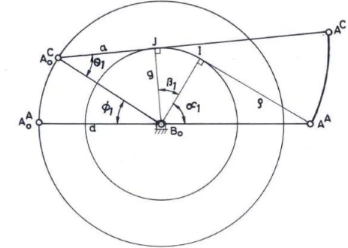
Indexing mechanisms need full rotational motion of input and output links with dwells in the output motion. The following facts3,10,11 are relevant in this context: (a) A fully rotating roller-crank (as input or output) demands a partial cam (fully rotating or oscillating); (b) Cam must be the output link when a dwell is required; (c) Roller-crank must be longer than the fixed link when the cam is required to rotate fully. Since the cam has to be of the reciprocating contact type, the same point [A] on the pitch profile of the cam (Fig.1) is occupied by the roller centre A (as A and A*) in two mutually conjugate positions of the mechanism. (r,) represent the polar coordinates of the point [A] on the cam pitch profile11. In this figure, the angle is defined to vary between 0 and 180 .
Following equations are obtained for two conjugate positions:
*
-=360-2. (1)
*
+=360. (2)
n1* +n1 = 2 (d/d). (3)
G = (g/a). (4)
is introduced as a rational transmission index11 inplace of the conventional transmission angle used by previous researchers3,10. Here, g is the leverage, perpendicular distance between the contact normal, (n), and Bo, the output
centre of rotation. Since the cam is the output and cam radius is a variable, the conventional transmission angle cannot be used. Relationship of the transmission index with transmission angle, is
sin
= (g/a)/ (r/a). (5)The leverage, g as well as transmission angle, are shown in Figure 2. Here, r is pitch curve (locus of roller centre) radius.
Fig.2. Leverage, g and transmission angle, for a RCCam
Since the transmission index depends on the direction of the contact normal, which in turn depends on the value of (d/d) = n1, the law of motion is considered in the form of n1 () in present investigation.
Since cam happens to be the output link, the transmission index (g/a) is repeated at the conjugate positions in the second half of the motion cycle. Therefore, when the motion law in the first 180° is chosen with transmission index control, the same control is automatically maintained in the second 180°.
2. Theories
2.1. Transmission quality control charts and their applications
Considering equivalent four bar linkage and using its construction diagram for determining n1 = (d/d), following relationship was determined between leverage, g and n1 :
/
2
/
cos
1
]
2
[
1
/
cos
]
[
1
/
sin
]
0
[
1 2 22 2
1
d
a
d
a
n
d
a
d
g
n
.
(6)
Solution of above equation gives two values of n1 at every value of for prescribed values of (a/d) and transmission index, (g/a). For this, writing the expression for determining the two values of n1 given by Eq. (6) and simplifying this expression further and further, the following form is obtained:
/
2
/
cos
1
]
[
1
]
cos
/
2
/
1
[
/
sin
/
]
cos
/
1
[
2
2 2
1
a
d
a
d
d
a
d
a
g
d
a
d
a
d
n
. (7)upper limit and a lower limit on n1 for given or G. Since these charts tell the transmission index limits at any value of , they are given the name, transmission quality control charts12. At = 0º, the value of n1 is inevitably equal to a/(a-d) and at = 180º , the value of n1 is inevitably equal to a/(a+d). At = sin-1(g/d) and at = 180º - sin-1(g/d), n1 becomes zero. Presence of 2 (d/d) curve in this chart greatly simplifies determination of n1* using Eq. (3). Optimal single dwell11 for prescribed minimum transmission index, Go= (g/a)o at a prescribed (a/d) is given by
d =180º -2 sin-1(g/d).
(8) The minimum radius of curvature oof the pitch profile occurs at = 0ºand is given by
(
o/a) =(
1
d
/
a
)
2
(
g
/
a
)
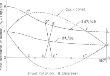
2o . (9) If the two dwells are placed in the same half of the motion cycle, even by allowing very high value of n2 and value low for the transition portions [Connecting dwell and 2 (d /d) portions in the prescribed motion law. Their conjugate portions then connect 2 (d /d) and dwell portions respectively.], sufficiently low indexing angle is obtained between the end of the first dwell and the beginning of the second. Not only this, the indexing period either becomes small or reduces the total dwell period. Thus the two dwells must not be kept in the same half of the motion cycle. It can be visualized what will happen if three dwells are placed in the same half of the motion cycle. It is therefore concluded that all the dwells must not be kept in the same half of the motion cycle.Placing of the two dwells in the different halves of the motion cycle is shown in Fig. 3 with the help of arrowheads. 2
d
/
d
and constant (g/d) curves are also drawn in the same figure.Fig. 3. Placing the two dwells in the different halves of the motion cycle
The first indexing angle is given by the area DEFL Q D. The dwell periods CD and F* E* will be the maximum attainable when from D to E is proceeded in the shortest possible time (input rotation), subject to the constraints. Hence, transition portion DE is taken constant = ocurve. It may be mentioned here again that o is given by Eq. (8). Transition curve DE is in the interior of the region bounded by the constant (g/d) curve. The (g/a) values are therefore higher than the minimum prescribed (g/a)othroughout the portion DE and its corresponding conjugate portion. DE may be chosen such that the area DEFLQD is 180. Alternatively DE may be chosen such that CD= F*E*. Since OK = 2a/(a-d) is generally much larger than QL = 2a/ (a+d), the d1max = CD will be considerably shorter than the d2max = F* E*. Dwell period CD is considerably shorter than F*E* in the former case13 while indexing angle DEFLQD will be less than 180 in latter case14.
2.2. Optimal motion diagram for three dwells
Fig. 4 shows the development of the motion diagram for three dwells. When two dwells were considered, the need to not space them too close to each other was one of the reasons to have them in the two different halves of the motion cycle. To meet this spacing requirement in the case of three dwells, the first dwell is placed to start near the beginning of the first half of the motion cycle, i.e. from = 1 and the second dwell to end near the end of the first half of the motion cycle, i.e. upto = 180- 2 (2 = 1). The third dwell is placed in the middle of the second half.
2.3. Determination of cam pitch profile
Geometrical construction of the cam pitch profile, consisting of portions corresponding to dwells, constant (g/d) [and hence constant (g/a) too] and constant (for the transition portions) is developed. Here, the inversion in which cam is fixed is considered. Optimal motion law was described in the previous section. Complete motion cycle (shown in Fig. 4 with the help of arrowheads for 360 of the input) is as follows: ACDEFGHBH*G* F*E*D*C* A. Points of the motion cycle are: A, C, D, E, F, G, H and B during prescribed half of the motion cycle; while B, H*, G*, F*, E*, D*, C* and A during determined half part of the motion cycle. The cam pitch profile is shown in Fig. 5.
Fig. 4. Development of the motion diagram for three dwells
The superscripts on the alphabetical letters naming the various points in this diagram are the names of the corresponding points of the motion diagram of Fig. 4. In other words: AA, AD, AF etc are the locations of the input-roller centre in the inversion and oE
A
o
A
A
,
etc. are the locations of the input-centre in the inversion. If a point of the motion diagram of Fig. 4 is possessing a “*” as a superscript for identifying a corresponding point in the second half , the name of the corresponding point in the cam pitch profile diagram (Fig. 5) should possess a superscript on the “*” as a superscript on the alphabetical letter. Since superscript to superscript on the alphabetical letter is to be avoided, such points like F* of Fig. 4 is shown asA
oF* and AF*
in Fig. 5. Since the cam is the output member and it is fixed in the inversion; location of the output centre Bo does not change.
2.3.1 Constant (g/d) curve at folded-in end
Now, the determination of the cam pitch profile is described.
A
oAB
oA
A in Fig. 5 is the configuration of the mechanism corresponding to point A of the motion diagram. The rotation of the cam from A to C is 1 and that of the roller-crank is 1. A to C is constant (g/d) curve. Determination of the cam pitch profile for this constant (g/d) curve is shown in Figure 6. As shown in this figure, this profile is involute. Expression for 1 will be as follows (refer Figure 6):1 = 180 - (90- 1) - 1- 1
or 1=90 + 1 - 1- 1. (10) where cos 1 =[g/(a-d)]=[Go/(1-Do)]. (11)
1 =
a
d
cos
1
a
d
2
g
2
/
g
or
1=
1
D
ocos
1
D
o
G
o/
G
o2 2
1
.
(12)
1 in Eq. (10) is in degrees while in Eq. (12) it is in radians. In Fig. 5; AoC, AC are thus located.
C to D being the dwell,
A
oD and C oA
will have the same location. Knowing the values of i1,i2;
(
A
oC,
A
oD),
(
A
oG,
A
oH),
(
A
oF*,
A
oE*)
are thus located.Fig. 6 Determination of cam pitch profile for constant (g/d) portion at folded in end
2.3.2 Constant (g/d) curve at stretched-out end
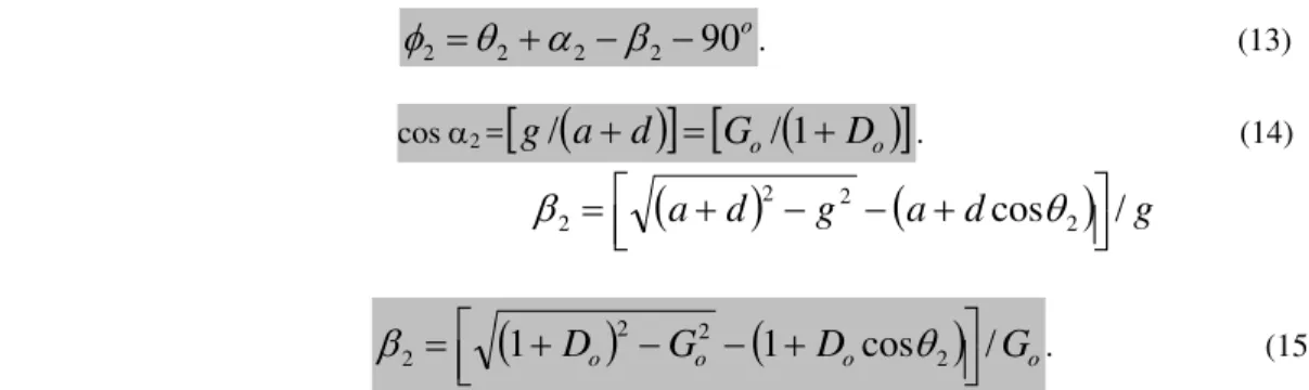
Since input roller- crank angle corresponding to point H is 180- 2 (2= 1); AH is located in Fig. 5. Since from H to B constant (g/d) curve is followed, corresponding profile will be involute. Expression for 2 will be as follows (refer Fig. 7):
2
2 2
2
90
or
o
90
2 2 22
. (13) wherecos 2 =
g
/
a
d
G
o/
1
D
o
. (14)
a
d
2g
2
a
d
cos
2
/
g
2
or
1
D
o
G
o
1
D
ocos
2
/
G
o 22
2
. (15)2 in Eq. (13) is in degrees while in Eq. (15) it is in radians. Thus, in Fig. 5
A
oB,
A
B are also located.Fig. 7 Determination of cam pitch profile for constant (g/d) portion at stretched out end
2.3.3 Transition portions DE and FG and three dwells
First dwell starts at AC (tangential to profile path AA AC) with centre at oD C
o
A
A
,
. Second dwell ends at AH (tangential to profile path AH AB ) with centre atA
oG,
A
oH. The third circular arc for dwell motion is centered at* *
,
oE Fo
A
A
. Points P1 and P2 are centre of circular arcs of radii o corresponding to the transition curves DE and FGof Fig. 4. An arc is marked with
A
oC,
A
oD as centre and (a+ o ) as radius and another arc is marked withA
oF*,
A
oE* as centre and (a- o ) as radius. P1 is their intersection. P2 is similarly found as the intersection of circular arcs ofradii (a- o ) and (a+ o ) respectively with centre
A
oG,
A
oH andA
oF*,
A
oE*. The points AD, AE*, AF*, AG are obtained by marking off ofrom P1and P2 along the linesP
1 2* 2 1 *
,
,
,
A
P
P
A
A
P
A
oC oE oF oG respectively. With P1 andP2 as centre circular arcs ADAE* and AF*AG respectively are drawn. These are the transition portions. Similarly with
)
,
(
),
,
(
),
,
(
* E*o F o H o G o D o C
o
A
A
A
A
A
A
as centre circular arcsA
CA
D,
A
GA
HandA
E*A
F*respectively are drawn. These are the three dwells as shown in Fig. 5.3. Results and Discussions
3.1 Determination of three equal maximized dwells
d2, d3 can be prescribed. However it can be stipulated that the three dwell periods should be equal (=d), without prescribing d. This involves the iteration after substituting d1= d2 = d3 =d in the following equations. Procedure of deriving these equations and capability limits tables are given in15 and is under publication. Few values of d so obtained along with first and second indexing angles are presented in Table 1. With increased prescribed Ro and/or Go values, d decreases.
]
2
/
)
sin[(
)
1
(
]
2
/
)
[(
sin
cos
2 1 2 1 2 2 1 1 i i o o i i o o dD
R
D
R
}
90
]
2
/
)
[(
{
1
1
2
i i . (16))
2
/
sin(
)
1
(
)
2
/
(
sin
cos
]
)
2
/
(
90
[
2 2 2 2 1 1 2 2 i o o o i o i dD
R
R
D
. (17)
)
2
/
sin(
)
1
(
)
2
/
(
sin
cos
)
2
/
(
2 2 2 2 1 1 3 i o o i o o i dD
R
D
R
]
2
/
)
sin[(
)
1
(
]
2
/
)
[(
sin
cos
2 1 2 1 2 2 1 i i o o o i i oD
R
R
D
. (18)
Table 1. Three equal maximized dwells provided by single roller-to-cam indexing mechanisms [The three entries for each specification are d, i1, i2 (all in degrees) in that order]
GO RO
0.20 0.26 0.30 0.36 0.40 0.46 0.10 39.4
70.7 75.0 34.5 69.5 79.7 30.7 67.8 83.3 23.8 63.2 89.8 17.9 57.7 95.3 5.0 42.8 106.5 0.15 33.2
76.5 77.3 27.9 75.2 81.7 23.7 73.4 85.2 16.0 68.6 91.6 9.5 63.0 97.0 0.20 26.1
83.7 80.3 20.2 82.0 84.6 15.6 80.1 88.0 7.0 74.9 94.3 0.25 17.6
92.8 84.0 11.1 90.7 88.2 5.9 88.4 91.6 0.30 6.7
105.2 88.1
3.2. Determination of three maximum extent dwell periods with equal indexing angles
Since each indexing angle is 120 for this case, substituting i1 = i2= 120 in the Eqs. (16), (17) and (18); expressions for three maximum extent dwell periods are obtained:
o o o o d
D
R
D
R
)
2
/
3
)(
1
(
)
4
/
3
(
cos
2 1 1
(
130
)
. (19)o o o o d
D
R
R
D
)
2
/
3
)(
1
(
)
4
/
3
(
cos
)
150
(
2 1 1 2
. (20) o o o o d
D
R
D
R
)
2
/
3
)(
1
(
)
4
/
3
(
cos
60
2 1 3
o o o oD
R
R
D
)
2
/
3
)(
1
(
)
4
/
3
(
cos
2 1
For prescribed Ro, Go values; Do is determined using Eq. (8). 1 = sin-1(g/d) as discussed earlier. Few values of d1,
d2 and d3 so obtained for various combinations of Ro and Go are shown in Table 2. With increased prescribed Ro and/or Go values, dwell periods decrease. d1 comes out extremely low in present case of equal indexing angles.
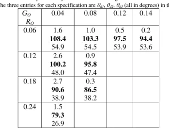
Table 2. Three maximum extent dwell periods with equal indexing angles provided by roller-to-cam indexing mechanisms
[The three entries for each specification are d1, d2, d3 (all in degrees) in that order]
GO RO
0.04 0.08 0.12 0.14
0.06 1.6 108.4
54.9
1.0 103.3
54.5
0.5 97.5 53.9
0.2 94.4 53.6 0.12 2.6
100.2 48.0
0.9 95.8 47.4 0.18 2.7
90.6 38.9
0.3 86.5 38.2 0.24 1.5
79.3 26.9
3.3. Determination of cam pitch profile and corresponding motion law
It is clear from Table 2 that the mechanism is not suitable for equal indexing angles. Although second dwell is very large (in the range of 80°- 100°) and third dwell is also large (30°- 60°) but first dwell is extremely low (1°- 2°). This can be employed where demand is for two prolonged and one instantaneous dwell. Situation improves very considerably in the case of three equal maximized dwells with equal indexing periods. Two examples are considered from this category for determination of cam pitch profile.
3.3.1 Example 1: prescribed Go =0.20 & Ro =0.20
Using Eqs. (8); Do =0.7172. 1= 2 = 16.19° using 1 = sin-1(g/d). Then, using Eqs. (11) & (12) and finally Eq. (10); 1(=29.32°) is determined. Similarily, using Eqs. (14) & (15) and finally Eq. (13); 2(=2.72°) is determined. For these prescribed Ro, Go values; d =26.1°, i1 = 83.7° and i2 = 80.3° from Table 1. If prescribed Ro, Go values are other than those available in this table, iteration is to be done as mentioned in section 3.1. With these values, cam pitch profile consisting of constant g/d (involute) portions, transition portions (circular arcs of radius o) and the three equal dwells between them is drawn following the procedure as discussed in section 2.3. Cam pitch profile for this example is shown in Fig. 8.
Since the contact point reciprocates on the cam pitch profile, corresponding to every point on the profile two configurations of the mechanism can be drawn. One configuration belongs to the prescribed part of the motion law (=0° to 180°) while the other belongs to the determined part of the motion cycle (=180° to 360°). It is clear from the Fig. 8 that during first 180° of input crank rotation, output cam rotates (1+ i1+ 2) i.e. just 115.74° only. Remaining 244.26° of cam rotation occurs during second 180° of input crank rotation. The two configurations (corresponding to any point of the cam pitch profile) along with cam radius, r form congruent triangles. Three pairs of such congruent triangles (one during each dwell) are shown in the figure. Corresponding to many other cam pitch profile points, and values were determined by drawing such congruent triangles but to avoid crowd on the figure these are not shown. Motion law ( vs. ) along with cam radius, r is shown in Table 3. This is self- explanatory. ,
, * and * corresponding to these congruent triangles can be determined from Table 3 by observing it carefully.
Table 3. Motion law for cam pitch profile example 1
(Deg.)
0 16.2 42.3 81 137.7 163.8 180 206 266 294 331 343.8 360
(Deg.)
0 29.3 29.3 69 113 113 115.7 148 193.3 193.3 245 296 360
r
(mm.)
Fig. 8 Determination of cam pitch profile for example 1
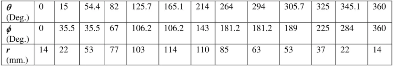
3.3.2 Example 2: prescribed Go =0.20 & Ro =0.10
Using Eq. (8); Do =0.7764. 1= 2 = 14.95° using 1 = sin-1(g/d). Then using various equations as mentioned in section 3.2.1, 1 (=35.52°) & 2 (=4.17°) are determined. For these prescribed Ro, Go values; d =39.4°, i1 = 70.7° and i2 = 75° from Table 1. Cam pitch profile for this example is shown in Fig. 9. It is clear from the figure that during first 180° of input crank rotation, output cam rotates (1+ i1+ 2) i.e. just 110.39° only. Remaining 249.61° of cam rotation occurs during second 180° of input crank rotation. Three pairs of congruent triangles (one during each dwell) are shown in Fig. 9. Corresponding to many other cam pitch profile points, and values were determined using congruent triangles (not shown in the figure). Motion law along with cam radius, r is shown in Table 4.
Table 4. Motion law for cam pitch profile example 2
(Deg.)
0 15 54.4 82 125.7 165.1 214 264 294 305.7 325 345.1 360
(Deg.)
0 35.5 35.5 67 106.2 106.2 143 181.2 181.2 189 225 284 360
r
(mm.)
14 22 53 77 103 114 110 85 63 53 37 22 14
4. Conclusions
Single roller-to-cam mechanism presented in this work is very simple and simple and direct control over cam profile curvature is possible. Since the transmission index is repeated at the conjugate positions in the second half of the motion cycle; once the motion law for the first half is prescribed taking care of transmission quality, automatic control is obtained in the second half. Placement of all the dwells in the same half of the motion cycle gives very small dwells and very unequal indexing angles and indexing periods. Hence investigation was done by placing two dwells in the first half and the third dwell in the middle of the second half of the motion cycle. The cam pitch profiles for optimal designs for single roller-to-cam indexing mechanisms providing three maximized equal/ unequal dwells with unequal/ equal indexing angles (and equal/ unequal indexing periods) were determined geometrically using the principle of kinematic inversion with intuitive conviction. Then, motion law was determined using congruent triangles formed by two conjugate configurations corresponding to any point of the cam pitch profile. References
[1] K S Tripathi. ‘To Investigate Simplest Intermittent Motion Mechanism’. TheInstitution of Engineers (India), vol 90, 2009, pp. 49- 54. [2] J H Bickford. ‘Mechanisms for Intermittent Motion’. Industrial Press, New York, 1972.
[3] K Hain. ‘Systematic and Full Rotatability of Three and More Linked Cam Mechanisms’. Konstruktion, vol 19, no 10, 1967, pp. 379- 388. [4] J S Beggs and R S Beggs. ‘Cam and Gears Join to Stop Shock Loads’. Product Engineering. Vol 28, no 10, 1957, pp. 84- 85.
[5] C Amarnath and B K Gupta. ‘Novel Cam-Linkage Mechanisms for Multiple Dwell Generation’. Proceedings of the Conference ‘Mechanisms-1974’, Institution of Mechanical Engineers, London, 1974.
[6] C Amarnath and B K Gupta. ‘On a Cam Mechanism with Multiple Dwell Capability’. Proceedings of the Fourth World Congress on the Theory ofMachines and Mechanisms, 1975.
[7] W L Cleghorm. ‘Mechanics of Machines’. Oxford University Press, New York, 2005.
[8] D H Gardener. ‘1800 Mechanical Movements, Devices and Appliances’. DoverScience Books, New York, 2008. [9] K H Hunt. ‘Profiled Follower Mechanisms’ Mechanism and Machine Theory, vol 8, 1973, pp. 371- 395.
[10] G Kiper. ‘Possibilities and Limits of the Simple Cam Mechanisms with Fully Rotating Driving and Driven Links’. Machinenbautechnik, vol
5, no 11, 1956, pp. 575- 582.
[11] K S Tripathi. ‘Cam Type Continuous Contact Intermittent Motion Mechanisms’. Ph D Thesis, Department of Mechanical Engineering, Indian Institute of Technology, Madras, India, 1991.
[12] K S Tripathi. ‘Development of Transmission Quality Control Charts for Single Roller- to- Cam Intermittent Motion Mechanisms’.
International Journal of Engineering Science and Technology, vol. 2, no 10, 2010, pp. 5265- 5274.
[13] K S Tripathi and K Lakshminarayana. ‘Optimal Designs and Capability Limits of Single Roller- to – Cam Indexing Mechanisms with Multiple Dwells’. Proceedings of the National Convention on Industrial Problems in Machines and Mechanisms, IPROMM, Bangalore, 1995, pp.64-74.
[14] K S Tripathi. ‘Single Roller- to- Cam Type Intermittent Motion Mechanisms: Optimal Designs and Capability Limits for Two Equal Maximized Dwells with Equal Indexing Periods’. Proceedings of the Eighth National Conference on Machines and Mechanisms, NACOMM, IIT Kanpur, 1997, pp.A69-A77.

![Table 1. Three equal maximized dwells provided by single roller-to-cam indexing mechanisms [The three entries for each specification are d , i1 , i2 (all in degrees) in that order]](https://thumb-eu.123doks.com/thumbv2/123dok_br/18382418.356553/8.918.148.772.197.397/table-maximized-provided-indexing-mechanisms-entries-specification-degrees.webp)