Space– time spreading MIMO-CDMA downlink systems using
constrained tensor modeling
Andre´ L.F. de Almeida
a, Ge´rard Favier
a,, Joa˜o C.M. Mota
baI3S Laboratory, University of Nice-Sophia Antipolis (UNSA), CNRS, France
bWireless Telecom Research Group, Federal University of Ceara´, Fortaleza, Brazil
a r t i c l e
i n f o
Article history:
Received 19 October 2007 Received in revised form 1 February 2008 Accepted 31 March 2008 Available online 12 April 2008
Keywords: Allocation matrices Blind detection Constrained tensor model Downlink transmission MIMO-CDMA system Multicode transmission Space–time spreading
a b s t r a c t
This paper considers the downlink of a multiple-input multiple-output (MIMO) code-division multiple-access (CDMA) system based on space–time spreading (STS) using multiuser/multicode transmission. A constrained tensor model is proposed for the STS transmitted signal. The new STS model generalizes existing ones by allowing multiuser spatial multiplexing with different code reuse/multiplexing patterns for each user. This model is parametrized by two allocation matrices with variable structure, which allow to control, respectively, the allocation of multiple data streams and spreading codes to the transmit antennas. A methodology is proposed to design these allocation matrices leading to finite sets of feasible STS schemes with guaranteed blind symbol recovery. The construction of feasible STS schemes for 2, 3 and 4 transmit antennas is presented as an illustration of this methodology. A blind receiver based on the alternating least squares algorithm is used for symbol recovery. The bit-error-rate performance of this receiver is tested and compared to some existing STS-based downlink transceivers.
&2008 Elsevier B.V. All rights reserved.
1. Introduction
It is well known that the use of multiple antennas at both the transmitter and receiver is promising since it potentially provides an increased spectral efficiency compared to traditional systems employing multiple antennas at the receiver only[1]. In the context of current and upcoming wireless communication standards, the integration of multiple-antenna and code-division multi-ple access (CDMA) technologies has been the subject of several studies[2].
Spatial multiplexing schemes for multiple-input multi-ple-output (MIMO)-CDMA systems were addressed in [2–4]. In [2], a BLAST-based CDMA system performing direct-sequence spreading on the symbols to be transmitted from each antenna is proposed, where each data stream is
associated with a spreading sequence. In[3], the multiple transmit antennas are organized in groups and a unique spreading code is used by all the antennas of the same group. The separation of the different groups at the receiver is done by using layered space–time processing. Focusing on the downlink reception,[4]also considers the spatial reuse of the spreading codes and proposes a chip-level equalizer at the receiver to handle the loss of code orthogonality.
Based on space–time coding principles, a space–time spreading (STS) scheme is proposed in[5]for providing maximum diversity gain without using extra spreading codes. Ref. [5] does not consider the multiuser inter-ference problem. In [6], a multilayered STS downlink model is proposed based on CDMA codes. The data stream is divided into multiple streams, or ‘‘layers’’, each one being spread by a unique STS sequence. In[7,8], a two-dimensional STS scheme based on Walsh–Hadamard spreading matrices is proposed for the downlink of a multiuser MIMO system.
Existing STS techniques are generally used in conjunc-tion with nonlinear multiuser detecconjunc-tion receivers based
Contents lists available atScienceDirect
journal homepage:www.elsevier.com/locate/sigpro
Signal Processing
0165-1684/$ - see front matter&2008 Elsevier B.V. All rights reserved. doi:10.1016/j.sigpro.2008.03.022
Corresponding author. Tel.: +33 492 942 736; fax: +33 492 942 896.
E-mail addresses:[email protected] (A.L.F. de Almeida),
on successive interference canceling or less-complex linear zero forcing (ZF) or minimum mean square error (MMSE) receivers. Also, performance is usually evaluated assuming perfect channel knowledge at the receiver, which is an optimistic assumption in practice.
In a seminal paper[9], the problem of uplink multiuser detection/separation is linked to a parallel factor (PARAF-AC) tensor model[10]. It is shown that the received signal sample associated with a receive antenna, a symbol and a chip, can be interpreted as an element of a three-way array, or third-order tensor. Using this interpretation,[9] shows that the use of tensor modeling allows the receiver to fully exploit three forms of diversity (time, space and code) for blindly recovering the transmitted symbols/ channel/codes. Generalizations of[9]to frequency-selec-tive channels were proposed in subsequent works[11–15], under different assumptions concerning the multipath propagation structure. However, all these works are limited to single-antenna transmissions.
Multiple-antenna transmissions based on tensor mod-eling are proposed in[16–19]. The approach of[16]relies on temporal-only spreading of the data streams and enjoys built-in blind symbol recovery. Since there is no spatial spreading of the data streams across the transmit antennas, no spatial spreading diversity is obtained in [16]. In [17], a generalized tensor model is proposed for MIMO-CDMA systems with blind detection. However, this modeling approach only considers spatial multiplexing and does not cover STS. The common characteristic of the tensor modeling approaches of[16,17]is that the number of data streams is restricted to be equal to the number of transmit antennas. The approach of[18]performs full STS and allows the number of data streams to be different from the number of transmit antennas, as opposed to [16,17]. A ‘‘constrained’’ STS model with variable structure was proposed in [20] by incorporating two constraint matricesinto the model which jointly control the alloca-tion of data streams and spreading codes to the transmit antennas.
In this paper, we present a STS model for the downlink of a MIMO-CDMA system with multiuser/multicode transmission. From the viewpoint of tensor modeling, the proposed STS model is a generalization of the uplink model of[20]to the case of multiuser spatial multiplexing (i.e. several user transmissions are multiplexed across the same set of transmit antennas). Another distinguishing feature of this work compared to previous ones is the design of the allocation matrices. We propose a complete parametrization of the two allocation matrices along with new design constraints. These design constraints allow to easily derive finite sets of feasible STS schemes with guaranteed blind symbol recovery for a given number of data streams, spreading codes and transmit antennas. These STS schemes go from full code reuse to full code multiplexing and have different levels of spectral effi-ciency. Design examples are presented for 2, 3 and 4 transmit antennas. The performance of different STS schemes is tested using a blind receiver combining multiuser interference elimination/despreading and an alternating least squares (ALS) algorithm for symbol recovery.
This paper is organized in the following manner. Section 2 describes the proposed STS MIMO-CDMA downlink model. In Section 3, a set of design constraints for the two allocation matrices is detailed. Some design examples are also illustrated in this section. The receiver algorithm is presented in Section 4. Simulation results for performance evaluation are provided in Section 5 and the paper is concluded in Section 6.
2. STS MIMO-CDMA downlink system
We consider the downlink of a single cell synchronous MIMO-CDMA wireless communication system with Q
active users and spreading factor P. The base-station and theq-th user are equipped with Ktransmit and M
receive antennas, respectively. For each user, a high-rate serial input stream is split into R fixed low-rate streams that are transmitted usingJorthogonal spreading codes with RpK and JpK. This type of scheme is
known as multicode transmission1[21,22]. After
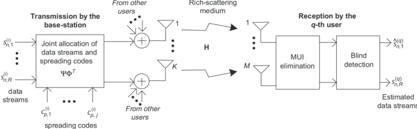
spread-ing, theRdata streams of all theQusers are then added together at each one of the Ktransmit antennas. Fig. 1 depicts the block-diagram of the proposed system, considering the i-th user in transmission and the q-th user in reception. The design of the joint stream-code allocation block at the transmitter and the two signal processing blocks at the receiver will be described in the next sections.
The wireless channel is assumed to be flat-fading and constant during a time-slot of durationNsymbol periods.2
The data streams of all users are transmitted with equal powers, which are normalized so that the average of the total transmitted power is independent of the total number RQ of data streams and of the number M of transmit antennas. We assume that the receiver has full knowledge of the associated spreading codes. The spreading codes are designed from user-specific OVSF (orthogonal variable spreading factor) codes as suggested in the high-speed downlink packet access (HSDPA) standard[23].
2.1. Transmitted signal model
Let hðqÞm
k be the channel response between the k-th transmit antenna and them-th receive antenna of theq-th user,q¼1;. . .;Q,sðqÞn;r¼:sðqÞððr1ÞNþnÞbe then-th symbol
of ther-th data stream transmitted to theq-th user, and
cðqÞp;jbe thep-th element of thej-th spreading code. Let us define uðqÞn;p;k¼:uðqÞk ððn1ÞPþpÞ as the ðn;p;kÞ-th sample of the q-th transmitted signal tensor UðqÞ2CNPK.
1Multiple short codes for a high-rate user should be orthogonal to
reduce the so-called ‘‘intercode interference’’. We point out that a random scrambling long pseudo-noise (PN) code common to all parallel short code users can be applied after spreading without affecting the orthogonality property between the users.
2The flat-fading assumption is considered here for simplicity
reasons. However, in the case of delay spread channels with path delays of the order of a few chips, we suggest to use a guard interval (also called ‘‘guard chips’’), with duration exceeding the maximum delay spread. The guard interval can be implemented by appending trailing zeros to each transmission burst (refer to[9]for further details).
We propose the following tensor model for the multiuser transmitted signal that is broadcast to theQusers:
un;p;k¼
XQ
i¼1
uðiÞn;p;k¼X
Q
i¼1
XR
r¼1
XJ
j¼1 sðiÞ
n;rcðiÞp;jcr;kfj;k, (1)
where cr;kand fj;k are typical elements of matricesW2 CRK and U2CJK. These matrices, which are common for all the users, can be viewed as stream-to-antenna
and code-to-antenna allocation matrices, respectively. They determine the reuse of users’ data streams and spreading codes across the transmit antennas. At this point, we define the basic structure of these matrices:
The columns of W and U are canonical vectors3associated with the following canonical bases, respec-tively:
EðRÞ¼ feðRÞ1 ;. . .;eðRÞR g; EðJÞ¼ feðJÞ1;. . .;eðJÞJ g,
WandUare both full rank matrices, which means that each canonical vector appears at least once inWandU.As each column vectorWkandUkis a canonical vector of the bases EðRÞ and EðJÞ, respectively, we havekWrk2¼a
r
andkUjk2¼bj, wherear40 andb
j40 denote the number
of times the canonical vectorseðRÞr andeðJÞj appear inWand U, respectively. It follows thatWWTandUUTare diagonal matrices given by
WWT¼diagða1;. . .;aRÞ; UUT¼diagðb1;. . .;bJÞ, (2)
and we have
traceðWWTÞ ¼X
R
r¼1 ar¼K,
traceðUUTÞ ¼X
J
j¼1 bj¼K.
The signaluðiÞn;p;kassociated with thei-th user, defined in (1), can be rewritten in the following manner:
uðiÞn;p;k¼ X
R
r¼1 sðiÞ
n;rcr;k
! XJ
j¼1 cðiÞp;jfj;k 0
@
1
A
¼aðiÞn;kbðiÞp;k, (4) whereaðiÞn;k¼ ½AðiÞn;kandbðiÞp;k¼ ½B
ðiÞ
p;kare typical elements
of the matrices
AðiÞ¼:SðiÞW2CNK,
BðiÞ¼:CðiÞ
U2CPK; i¼1;. . .;Q. (5)
A matrix collectingNsymbolsPchips transmitted from thek-th transmit antenna to thei-th user is defined as
UðiÞk¼
uðiÞ1;1;k uðiÞ1;P;k
.. .
.. .
uðiÞN;1;k uðiÞN;P;k
2
6 6 6 4
3
7 7 7 5
2CNP. (6)
This matrix can be factored in the following manner:
UðiÞk¼AðiÞkBkðiÞT¼SðiÞWkUTkCðiÞT
or, equivalently,
UðiÞk¼SðiÞCkCðiÞT, (7)
where
Wk¼ ½c1;k cR;kT2CR,
Uk¼ ½f1;k fJ;kT2CJ (8)
and
Ck¼WkUTk2CRJ (9)
determines the coupling between data streams and spreading codes at thek-th transmit antenna.
From (4) and (7), the overall (multiuser) transmitted signal tensor obtained by summing over the Q user
spreading codes
K M
H
data streams
From other users
From other users Joint allocation of
data streams and
spreading codes MUI
elimination
Blind detection Rich-scattering
medium
Estimated data streams
Transmission by the base-station
Reception by the q-th user
• • •
• • •
• • •
• • •
• • •
• • •
n,(i)1
(i)
(i) (i)
n,1 (q)
n,R
p,1 p, j
^
n,R
(q) ΨΦ
ΨΦT
1 1
Fig. 1.Block-diagram of the proposed downlink MIMO-CDMA system.
3A canonical vector eðNÞ
n 2RN is a unitary vector containing an
contributions is given by
un;p;k¼X
Q
i¼1
uðiÞn;p;k¼X
Q
i¼1 aðiÞn;kbðiÞp;k
¼X
Q
i¼1
SðiÞnCkCðiÞTp , (10)
where
SðqÞn ¼ ½sðqÞn;1 sðqÞn;R 2C1R,
CðqÞp ¼ ½cðqÞ
p;1 cðqÞp;J 2C1J.
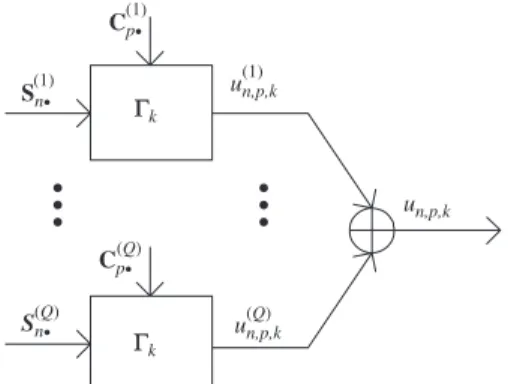
Model (10) leads to the downlink transmission block-diagram shown inFig. 2.
We also define a stream-to-code allocation matrix
as follows:
C¼X
K
k¼1
Ck¼WUT2CRJ. (11)
2.2. Received signal model
In absence of noise, the discrete-time baseband version of the signal received by them-th antenna of theq-th user can be represented by a tensorXðqÞ2CNPMwith typical element xðqÞn;p;m¼:xðqÞmððn1ÞPþpÞ, q¼1;. . .;Q. Using (1),
we arrive at the following tensor model for the received signal:
xðqÞ n;p;m¼
XK
k¼1
hðqÞm;kun;p;k
¼X K k¼1 XQ i¼1 XR r¼1 XJ j¼1 sðiÞ
n;rcðiÞp;jh ðqÞ
m;kcr;kfj;k (12)
or equivalently xðqÞ n;p;m¼ XQ i¼1 XK k¼1 XR r¼1 sðiÞ
n;rcr;k
!
hðqÞm;k X J
j¼1 cðiÞ
p;jfj;k
0 @ 1 A ¼X Q i¼1 XK k¼1
aðiÞn;khðqÞm;kbðiÞp;k
!
, (13)
whereaðiÞn;kandbðiÞp;kare defined in (4).
Let us defineXðqÞmas a matrix collectingNsymbolsP
chips of the signal received at them-th transmit antenna
of theq-th user:
XðqÞm¼
xðqÞ1;1;m xðqÞ1;P;m
.. .
.. .
xðqÞN;1;m xðiÞN;P;m
2 6 6 6 4 3 7 7 7 5
2CNP. (14)
Note that XðqÞm is the m-th slice of the received signal tensorXðqÞ2CNPMobtained by slicing it along its third dimension. This matrix-slice can be factored as
XðqÞm¼X
Q
i¼1
AðiÞdiagðhðqÞm;1;. . .;hðqÞm;KÞBðiÞT
¼X
Q
i¼1
SðiÞWDmðHðqÞÞUTCðiÞT,
where diagðhðqÞm;1;. . .;hðqÞm;KÞforms a diagonal matrix holding
hðqÞm;1;. . .;hm;KðqÞ on its main diagonal, whileDmðHðqÞÞforms a
diagonal matrix from them-th row of HðqÞ2CMK. This matrix-slice can be rewritten in a block factorized form as
XðqÞm¼SHðqÞmCT, (15)
with
S¼ ½Sð1Þ;. . .;SðQÞ 2CNRQ,
C¼ ½Cð1Þ;. . .;CðQÞ 2CPJQ, (16)
being the multiuser symbol and code matrices, and
HðqÞm ¼
WDmðHðqÞÞUT
. . .
WDmðHðqÞÞUT
2 6 6 6 4 3 7 7 7 5 |fflfflfflfflfflfflfflfflfflfflfflfflfflfflfflfflfflfflfflfflfflfflfflfflfflfflfflfflfflfflfflfflfflfflffl{zfflfflfflfflfflfflfflfflfflfflfflfflfflfflfflfflfflfflfflfflfflfflfflfflfflfflfflfflfflfflfflfflfflfflffl} Qtimes
¼WDmðHðqÞXÞUT, (17) being the downlink channel associated with the q-th receiver, where
W¼IQW2CRQKQ, U¼IQU2CJQKQ, X¼1TQIK2CKKQ
are block-constraint matrices of the transmission model,
1Q being the ‘‘all-ones’’ vector of dimension Q. Taking
these definitions into account, we obtain the following compact writing for the m-th sliceXðqÞ
m of the received
signal tensor:
XðqÞm¼SWDmðHðqÞXÞUTC T
. (18)
Although fW;U;Xg are three constraint matrices of model (18), it is worth noting that W and U are ‘‘configurable’’ matrices with variable canonical structure characterizing the STS transmission scheme. For this reason, W can be interpreted as a stream-to-antenna allocation matrix, whileUas a code-to-antenna allocation matrix. On the other hand,Xis a ‘‘fixed’’ constraint matrix that only depends on the numbersKof transmit antennas andQof users. The design of these matrices is the subject of the next section.
Sn • (1) Cp • (1) un,p,k un,p,k (1) un,p,k (Q) Cp • (Q) S n• Γk Γk (Q) • • • • • •
Fig. 2.Transmission block-diagram of the proposed downlink MIMO-CDMA system.
3. Design of the allocation matrices
In this section, we present a complete parametrization of the allocation matrices Wand U. Using this parame-trization, a set of four design constraints are proposed which allow to easily derive a codebook of feasible STS schemes with guaranteed blind symbol recovery for a given number of data streams, spreading codes and transmit antennas. Then, design examples are presented for 2;3 and 4 transmit antennas.
Recall that the same allocation pattern of data streams and spreading codes is assumed for theQusers, since we haveW¼IQWandU¼IQU. Therefore, we will focus
on the design of the allocation matricesWandU(instead ofWandU) without loss of generality. The use of different per-user allocation patterns is a straightforward general-ization of the proposed tensor model given in (1).
Let us partition theKtransmit antennas intoRsubsets ofKrantennas each,r¼1;. . .;R, withRpK, each antenna
of the r-th subset being associated with the r-th data stream. So, the r-th data stream is spread across Kr
antennas. TheseKr antennas are then partitioned intoJr
subsets associated with different spreading codes, thejr
-th code being reusedgr;j
r times,jr¼1;. . .;Jr. The stream-to-antenna allocation matrix W is partitioned into R
blocks, the r-th block containing Kr columns. The structure of this matrix is given by
W¼
½1 1 |fflfflfflfflfflffl{zfflfflfflfflfflffl}
K1
½1 1 |fflfflfflfflfflffl{zfflfflfflfflfflffl}
K2
. . .
½1 1 |fflfflfflfflfflffl{zfflfflfflfflfflffl}
KR 2
6 6 6 6 6 6 6 6 6 6 6 6 6 6 4
3
7 7 7 7 7 7 7 7 7 7 7 7 7 7 5
¼ ½W1 Wr WR, (19)
with Wr of dimension RKr, and the r-th row of W
given by
Wr¼ ½0 0 |fflfflffl{zfflfflffl}
Kr1
1 1 |fflfflfflffl{zfflfflfflffl}
Kr
0 0 |fflfflfflffl{zfflfflfflffl}
KKr
ð1KÞ
and
Kr¼
Xr
i¼1
Ki; KR¼K.
The general structure ofWcan be formulated with the aid of canonical vectors in the following manner:
W¼ ½1TK1eðRÞ1 ;. . .;1TKReðRÞR .
Similarly, the code-to-antenna allocation matrix U is partitioned intoRblocks, ther-th block being partitioned intoJrsub-blocks. This matrix has the following structure
U¼ ½U1 Ur UR, (20)
where
;
(21)
0J
r1Kr and0ðJJrÞKr are zero matrices of dimensionJr1 Kr andðJJrÞ Kr, respectively, where
Jr¼X
r
i¼1
Ji; JR¼J
and
ðUrÞJ
r1þjr¼ ½0|fflfflfflffl{zfflfflfflffl} 0
gr;jr1
1 1 |fflfflfflffl{zfflfflfflffl}
gr;jr
0 0 |fflfflfflffl{zfflfflfflffl}
Krgr;jr
ð1KrÞ
denotes the jr-th row of the nonzero row-block of Ur, where
gr;jr¼ Xjr
l¼1
gr;l; r¼1;. . .;R,
withgr;Jr ¼Kr.
Using the canonical vectors, the general structure ofUcan be explicited as
U¼ ½1Tg
1;1e ðJÞ
1;. . .;1Tg1;j1e ðJÞ J1;1
T g2;1e
ðJÞ J1þ1;. . .;1
T gR;JRe
ðJÞ J .
We have to notice that the r-th row of W defines the allocation of the r-th data stream to Kr transmit
antennas. Similarly, the jr-th row of the nonzero row-block of Ur defines the allocation of the jr-th code togr;j
r antennas that transmit ther-th data stream. When cr;kfj
r;k¼1, it means that the jr-th spreading code is used by the k-th transmit antenna to transmit the r-th data stream. The element gr;j
r of C defined in (11), and given by
gr;jr¼ XK
k¼1
cr;kfjr;k (22)
denotes the reuse factor of the jr-th spreading code. It corresponds to the number of transmit antennas trans-mitting the r-th data stream using the jr-th spreading code,jr¼1;. . .;Jr, whereJr is the number of spreading codes used to transmit ther-th data stream by means ofKr
transmit antennas, so that we have
XR
r¼1
XJr
jr¼1 gr;j
3.1. Design constraints (relations linking Jr, Krandgr;jr)
Note that W and U are parametrized by the set of parametersfJr;Kr;gr;jrg,r¼1;. . .;R. Recall that
Jr: number of codes allocated to ther-th data stream; Kr: spatial reuse factor of (i.e. number of antennas allocated to) ther-th data stream; gr;jr: spatial reuse factor of thejr-th code allocated to ther-th data stream.
In the following, we provide some design constraints for the allocation matricesWand Uwith the two following objectives:
1. To guarantee the uniqueness of the symbol matrixS
thus allowing a blind symbol recovery.
2. To simplify the transmission design by eliminating redundant STS schemes from the set of possible choices covered by the general design framework.
Constraint 1. The spatial reuse factor of the jr-th code cannot exceed the spatial reuse factor of the r-th data stream, which leads to
gr;jrpKr. (23)
This constraint implies thattransmit antennas transmitting different data streams always use different spreading codes. This design constraint is related to the blind recovery of the transmitted symbols. To be specific, the reuse of the same spreading code by any two different data streams would induce a rotational indeterminacy affecting the corresponding columns of the symbol matrix S, i.e. this matrix would be identifiable only up to a post-multi-plication by a nonsingular transformation matrix (refer to [20]for further details).
Constraint 2. The code reuse factor does not exceed the spatial reuse factor of ther-th data stream:
JrpKr, (24)
which implies that only one spreading code is used at each transmit antenna, i.e. we do not allow multiple spreading codes associated with the same data stream to be multiplexed at the same transmit antenna. This constraint is merely a choice that simplifies the design of the allocation matrices by reducing the set of possible transmission schemes. In other words, transmission structures where two different codes are used by the same data stream at the same transmit antenna are not considered in our design.
From (24), we get
J¼X
R
r¼1 JrpX
R
r¼1 Kr¼K.
SinceRpJ(R¼Jonly occurs ifJr¼1 forr¼1;. . .;R), we obtain the following inequalities relating the number of data streams, spreading codes and transmit antennas:
RpJpK. (25)
Constraint 3. The spatial reuse factors of the R data streams are chosen in a decreasing order:
KrXKr0; 8ror0; r;r0¼1;. . .;R. (26)
This constraint eliminates alternative (redundant) designs that are just permutation of the rows ofWin (19).
Constraint 4. The spatial reuse factors of the J1;. . .;JR
spreading codes for theR data streams are chosen in a decreasing order:
maxðgr;1;. . .;gr;JrÞXmaxðgr0;1;. . .;gr0;Jr0Þ,
8ror0; r;r0¼1;. . .;R
and
gr;iXgr;j; 8ioj; i;j¼1;. . .;Jr. (27)
This constraint is composed of two inequalities. The first one eliminates redundant designs which are just permu-tations of the blocksU1;. . .;URin (20). On the other hand, the second inequality avoids row permutations within each blockUr,r¼1;. . .;Rin (21). It should be noted that for given stream-to-antenna and code-to-antenna tion patterns, there are different stream-to-code alloca-tion patterns which are unimportant to the context of this work. The goal of the two inequalities in (27) is to fix the stream-to-code allocation, thus eliminating redundant choices forU.
Remark 1. In practice,WandUcan be designed by taking users’ requirements such as transmit diversity gain and data-rate into account. These requirements can be used to provide additional guidelines for choosingJr,Kr andgr;jr. Performance-oriented optimization of the allocation ma-trices based on a priori knowledge about the channel could resort to limited feedback precoding methods [24,25]. This research topic is beyond the scope of this work and is under investigation.
3.2. Spectral efficiency
Taking the above design requirement and spreading matrix structure into account, the rate of the proposed STS model can be calculated by using the simple formula: SF¼ RQ
P
log2ðmÞ ðbits per channel useÞ, (28) wherem is the modulation cardinality. In this work, we make the assumption PXJQ, which means that the spreading code matrix C2CPJQ defined in (16) is full column-rank (the reason for this assumption will be clarified in Section 4). In order to facilitate the comparison of different STS schemes in terms of spectral efficiency, we assumeP¼JQwithout loss of generality. In this case (28) is equivalent to
SF¼ R
J log2ðmÞ. (29)
Recall that the two allocation matricesW2CRK andU2 CJK are full row-rank, i.e. rankðWÞ ¼R and rankðUÞ ¼J. Therefore, the spectral efficiency SF in (29) can be calculated from the ranks of W and U, i.e. SF¼ ðrankðWÞ=rankðUÞÞlog2ðmÞ.
3.3. Design examples
For a fixed numberKof transmit antennas, there is a finite setSKðW;UÞof feasible transmit schemes satisfying
the design constraints given in the previous section. Each element of this set is given by a different matrix pair ðW;UÞ. Here, we present feasible sets of STS schemes forK¼2, 3 and 4 transmit antennas, which is generally the case in practical MIMO-CDMA downlink settings. The allocation matrices W and U can then be derived from a set ofgenerating arrays as shown in the examples below.
K¼2: The set S2ðW;UÞ of feasible schemes can be
derived from the following generating arrays:
g2¼ ½1 1; G11¼I2,
and we have
S2ðW;UÞ ¼ fðg2;g2Þ
|fflfflfflffl{zfflfflfflffl}
J¼1
;ðg2;G11Þ
|fflfflfflfflffl{zfflfflfflfflffl}
J¼2
|fflfflfflfflfflfflfflfflfflfflfflfflfflffl{zfflfflfflfflfflfflfflfflfflfflfflfflfflffl}
R¼1
;ðG11;G11Þ
|fflfflfflfflfflffl{zfflfflfflfflfflffl}
R¼J¼2
g.
Therefore, three transmit schemes are possible forK¼2. The first one, where W¼U¼g2, indicates that a single data stream is transmitted over both transmit antennas using the same spreading codeðR¼J¼1Þ. This is a full transmit spatial diversity scheme with full code reuse. From (9) we have
C1¼C2¼1.
The transmitted signal matrices are given by (7)
UðqÞ1¼UðqÞ2¼sðqÞcðqÞT.
In the second scheme we have W¼g2 and U¼G11,
meaning that a single data stream is now associated with two different spreading codes at the first and second transmit antennas. In this case, transmit spatial diversity with full code multiplexing takes place, and we have
C1¼ ½1 0; C2¼ ½0 1.
The transmitted signal matrices are given by
UðqÞ1¼sðqÞCðqÞT
1 ; U
ðqÞ 2¼sðqÞC
ðqÞT 2 .
Finally, the third schemeW¼U¼G11indicates that two
different data streams are transmitted from both antennas using different spreading codes, which corresponds to a full spatial multiplexing scheme with full code multi-plexing, i.e. different codes are used at each antenna. We have
C1¼ 1 0
0 0
; C2¼ 0 0
0 1
.
In this case, the transmitted signal matrices are given by
UðqÞ1¼SðqÞ1CðqÞT1 ; UðqÞ2¼SðqÞ2CðqÞT2 .
This scheme is similar to that of [2], although the modeling approach used here is different. Note that, for each one of the STS schemes mentioned above, the corresponding spectral efficiency can be calculated using (29), for a fixed modulation cardinality. Note that the first
and third schemes ofS2ðW;UÞhave SF¼log2ðmÞwhile the
second one has SF¼log2ðmÞ=2.
K¼3: Consider the three generating arrays as follows:g3¼ ½1 1 1; G21¼
1 1 0
0 0 1
,
G111¼
1 0 0
0 1 0
0 0 1
2
6 4
3
7 5.
Using the proposed design for the constraint matrices, we get the following feasible setS3ðW;UÞfrom these
generat-ing arrays:
S3ðW;UÞ
¼ ðg3;g3Þ
|fflfflfflffl{zfflfflfflffl}
J¼1
;ðg3;G21Þ
|fflfflfflfflffl{zfflfflfflfflffl}
J¼2
;ðg3;G111Þ
|fflfflfflfflfflffl{zfflfflfflfflfflffl}
J¼3
|fflfflfflfflfflfflfflfflfflfflfflfflfflfflfflfflfflfflfflfflfflfflfflffl{zfflfflfflfflfflfflfflfflfflfflfflfflfflfflfflfflfflfflfflfflfflfflfflffl}
R¼1
;
8 > > > > > <
> > > > > :
ðG21;G21Þ
|fflfflfflfflfflffl{zfflfflfflfflfflffl}
J¼2
;ðG21;G111Þ
|fflfflfflfflfflfflffl{zfflfflfflfflfflfflffl}
J¼3
|fflfflfflfflfflfflfflfflfflfflfflfflfflfflfflfflfflffl{zfflfflfflfflfflfflfflfflfflfflfflfflfflfflfflfflfflffl}
R¼2
;ðG111;G111Þ
|fflfflfflfflfflfflfflffl{zfflfflfflfflfflfflfflffl}
R¼J¼3
9 > > > > > =
> > > > > ;
yielding a total of six transmit schemes. The first scheme
W¼U¼g3corresponds to a full transmit diversity scheme
with full code reuse. The last oneW¼U¼G111is a spatial
multiplexing system using different spreading codes at each transmit antenna. Between these two solutions, we have four intermediary schemes which are different combinations of transmit diversity and spatial multiplex-ing with different code reuse patterns. For instance, the second and third schemes transmit a single data stream while the fourth and fifth schemes transmit two data streams using two and three spreading codes, respectively. More explicitly, for the fifth scheme (R¼2 andJ¼3), the transmitted signal matrices are
UðqÞ1¼SðqÞ1CðqÞT1 ; UðqÞ2¼SðqÞ1CðqÞT2 ,
UðqÞ3¼SðqÞ2CðqÞT3 ,
which shows that the first data streamðSðqÞ1Þis transmitted by the two first antennas (k¼1 and 2) using two different codes (CðqÞ1 andCðqÞ2), while the second data streamðSðqÞ2Þis transmitted by the third antennaðk¼3Þ using the third codeðCðqÞ3Þ. It is worth noting that three levels of spectral efficiency are presented in the setS3ðW;UÞ. For instance,
assuming QPSK modulationðm¼2Þ, the first, fourth and sixth STS schemes (i.e. those with R¼J) have the same spectral efficiency SF¼2 bits per channel use. The second, third and fifth STS schemes have SF¼12; 1
3and23bits per
channel use, respectively.
g4¼ ½1 1 1 1; G31¼
1 1 1 0
0 0 0 1
,
G22¼
1 1 0 0
0 0 1 1
; G211¼
1 1 0 0
0 0 1 0
0 0 0 1
2 6 4 3 7 5,
G1111¼
1 0 0 0
0 1 0 0
0 0 1 0
0 0 0 1
2 6 6 6 4 3 7 7 7 5 .
Using the proposed design constraints, the feasible set
S4ðW;UÞis composed of 14 different transmit schemes:
We remark thatðG31;G31ÞandðG22;G22Þare two schemes
having the same number of transmitted data streams and spreading codes but differing in their allocation pattern to the transmit antennas. Let us consider now two schemesðG31;G211ÞandðG22;G211Þ. Both transmit two
data streams over four transmit antennas using three spreading codes.
Let us comment scheme ðG31;G211Þ. It transmits the
first data stream over three transmit antennas using two different spreading codes (one is reused at two transmit antennas) and the second data stream is transmitted by a single antenna using a single spreading code. On the other hand, the schemeðG22;G211Þtransmits both data streams
by assigning two transmit antennas to each one. The first data stream is associated with a single spreading code while the second one uses two different spreading codes. We can distinguish six spectral efficiency levels in
S4ðW;UÞ, which are SF¼1; 14; 13; 12; 23and34bits per channel
use (assuming QPSK modulation), and we have four schemes with SF¼1; two schemes with SF¼12; and one scheme with SF¼1
4; 13or34.
It is worth noting thatnot allthe pairwise combina-tions of generating arrays is a feasible transmit scheme ensuring blind symbol recovery. For instance, the scheme
ðW;UÞ ¼ ðG22;G31Þis not feasible. In this scheme, the first
spreading code is reused by the twodifferentdata streams, inducing a coupling between different data streams. It is shown in [20] that such a coupling leaves rotational freedom within the antenna subset associated with the second data stream, thus affecting uniqueness ofS(only
the first data stream can be uniquely recovered). There-fore, care must be taken when deriving the MIMO-CDMA transmit schemes from the generating arrays.
4. Receiver algorithm
In this paper, we are interested to blindly detect the transmitted data streams of each user separately without the knowledge about (ora prioriestimate of) the MIMO downlink channel. We consider a simple blind receiver composed of two processing stages. The first one
attempts to mitigate multiuser interference using code-matched filtering/despreading. The second stage works on the resulting signal tensor after the code-matched filtering/despreading operation, and performs blind symbol recovery separately for each user, by means of the alternating LS algorithm. We assume that the q-th user has perfect knowledge of its code matrixCðqÞ.
Requirement 1. Multiuser interference elimination by each user requires
CðqÞTCðq0Þ¼ IJ if q¼q 0;
0 if qaq0; (
fq;q0g ¼1;. . .;Q.
Note that this condition is equivalent to CTC¼IJQ,
which arrives whenPXJQ.
Remark 2. If Requirement 1 is not satisfied, multiuser detection can alternatively be used at the receiver without despreading, as in [9,20]. This is the case when ICI is present and the code matrixCis unknown and nonorthogonal. The price to pay when multiuser detection is used is an increased receiver complexity.
After the despreading operation by each user, we have the following interference-free model:
YðqÞ1
.. .
YðqÞM
2 6 6 6 4 3 7 7 7 5 ¼
XðqÞ1
.. .
XðqÞM
2 6 6 6 4 3 7 7 7 5
FðqÞ; FðqÞ¼ ½CðqÞ2CPJ.
From (18), the resulting (single-user) received signal model can be written, for theq-th user, as
S4ðW;UÞ ¼ ðg4;g4Þ
|fflfflfflffl{zfflfflfflffl}
J¼1
;ðg4;G31Þ;ðg4;G22Þ
|fflfflfflfflfflfflfflfflfflfflfflfflfflfflffl{zfflfflfflfflfflfflfflfflfflfflfflfflfflfflffl}
J¼2
;ðg4;G211Þ
|fflfflfflfflfflffl{zfflfflfflfflfflffl}
J¼3
;ðg4;G1111Þ
|fflfflfflfflfflfflffl{zfflfflfflfflfflfflffl} J¼4 |fflfflfflfflfflfflfflfflfflfflfflfflfflfflfflfflfflfflfflfflfflfflfflfflfflfflfflfflfflfflfflfflfflfflfflfflfflfflfflfflfflfflfflfflfflffl{zfflfflfflfflfflfflfflfflfflfflfflfflfflfflfflfflfflfflfflfflfflfflfflfflfflfflfflfflfflfflfflfflfflfflfflfflfflfflfflfflfflfflfflfflfflffl} R¼1 8 > > > > > < > > > > > :
ðG31;G31Þ;ðG22;G22Þ
|fflfflfflfflfflfflfflfflfflfflfflfflfflfflfflfflffl{zfflfflfflfflfflfflfflfflfflfflfflfflfflfflfflfflffl}
J¼2
;ðG31;G211Þ;ðG22;G211Þ
|fflfflfflfflfflfflfflfflfflfflfflfflfflfflfflfflfflfflffl{zfflfflfflfflfflfflfflfflfflfflfflfflfflfflfflfflfflfflffl}
J¼3
;ðG31;G1111Þ;ðG22;G1111Þ
|fflfflfflfflfflfflfflfflfflfflfflfflfflfflfflfflfflfflfflfflffl{zfflfflfflfflfflfflfflfflfflfflfflfflfflfflfflfflfflfflfflfflffl}
J¼4
|fflfflfflfflfflfflfflfflfflfflfflfflfflfflfflfflfflfflfflfflfflfflfflfflfflfflfflfflfflfflfflfflfflfflfflfflfflfflfflfflfflfflfflfflfflfflfflfflfflfflfflfflfflfflfflfflfflfflfflfflfflfflfflfflfflfflffl{zfflfflfflfflfflfflfflfflfflfflfflfflfflfflfflfflfflfflfflfflfflfflfflfflfflfflfflfflfflfflfflfflfflfflfflfflfflfflfflfflfflfflfflfflfflfflfflfflfflfflfflfflfflfflfflfflfflfflfflfflfflfflfflfflfflfflffl}
R¼2
ðG211;G211Þ
|fflfflfflfflfflfflfflffl{zfflfflfflfflfflfflfflffl}
J¼3
;ðG211;G1111Þ
|fflfflfflfflfflfflfflfflffl{zfflfflfflfflfflfflfflfflffl}
J¼4
|fflfflfflfflfflfflfflfflfflfflfflfflfflfflfflfflfflfflfflfflfflffl{zfflfflfflfflfflfflfflfflfflfflfflfflfflfflfflfflfflfflfflfflfflffl}
R¼3
;ðG1111;G1111Þ
|fflfflfflfflfflfflfflfflfflffl{zfflfflfflfflfflfflfflfflfflffl} R¼J¼4 9 > > > > > = > > > > > ; .
YðqÞm¼SðqÞWDmðHðqÞÞUT2CNJ. (30)
We can obtain the two other following slice representa-tions for theq-th user interference-free signal:
YðqÞ
n¼UDnðSðqÞWÞHðqÞT2CJM,
YðqÞj ¼HðqÞDjðUÞWTSðqÞT2CMN. (31)
By concatenating column-wise each set of slicesfYðqÞjgand
fYðqÞng, we obtain
YðqÞ1 ¼
YðqÞ1
.. .
YðqÞJ
2
6 6 6 4
3
7 7 7 5
¼
HðqÞD
1ðUÞ
.. .
HðqÞDJðUÞ
2
6 6 6 4
3
7 7 7 5 WT
|fflfflfflfflfflfflfflfflfflfflfflfflffl{zfflfflfflfflfflfflfflfflfflfflfflfflffl}
Z1ðHðqÞÞ2CMJR
SðqÞT¼ ðU}HðqÞÞWTSðqÞT,
(32)
YðqÞ2 ¼
YðqÞ1
.. .
YðqÞN
2
6 6 6 4
3
7 7 7 5
¼
UD1ðSðqÞWÞ
.. .
UDNðSðqÞWÞ
2
6 6 4
3
7 7 5
|fflfflfflfflfflfflfflfflfflfflfflffl{zfflfflfflfflfflfflfflfflfflfflfflffl}
Z2ðSðqÞÞ2CJNK
HðqÞT¼ ðSðqÞ
W}UÞHðqÞT.
(33)
Requirement 2. Assuming JX2, the identifiability of the symbol and channel matrices SðqÞ andHðqÞ in the LS sense requires thatZ1ðHðqÞÞandZ2ðSðqÞÞbe full column-rank,and we must have MJXR and JNXK.
Remark 3. The full rank assumption is reasonable in practice, if: (i) the entries of the channel matrix are assumed to be independently and randomly drawn from an absolutely continuous distribution, and if (ii) ‘‘persistence of excitation’’ of the transmitted symbols holds. The sufficient condition of[9], which involves the concept ofk-rank, does not apply to model (30), since the
k-rank of W and U are always equal to one, except for allocation schemes corresponding to a full spatial multi-plexingðW¼IKÞand/or a full code multiplexingðU¼IKÞ.
The derivation of a tighter sufficient condition for blind symbol recovery in our case is under investigation.
The second stage of the receiver is concerned with blind symbol recovery based on the interference-free received signal. The alternating least squares (ALS) algorithm, which is the classical solution for estimating the compo-nent matrices of a tensor model, is considered here. In our case, by using the knowledge ofWandU, this algorithm consists in alternated estimations of the symbolðSðqÞÞand channelðHðqÞÞmatrices. At each step of this algorithm, one component matrix is estimated in the LS sense, while the other is fixed to its value obtained at the previous step. At the beginning of the algorithm, H^
ð0Þ is randomly
initi-alized. At thet-th iteration we have
^
SðqÞTðtÞ ¼ ½Z1ðH^ ðqÞ ðt1ÞÞyY~
ðqÞ
1 ; H^
ðqÞT ðtÞ ¼ ½Z2ðS^
ðqÞ ðtÞÞyY~
ðqÞ
2 ,
where ðÞy denotes the matrix pseudo-inverse, Y~ðqÞ
j ¼
YðqÞj þVðqÞj ,j¼1;2, is the noisy version ofYðqÞj , the additive white gaussian noise matrix being represented byVðqÞj , and
fYðqÞ1 ;Z1ðHðqÞðtÞÞg and fY ðqÞ 2 ;Z2ðS^
ðqÞ
ðtÞÞg are defined in (32) and
(33), respectively. Convergence at the t-th iteration is decided when the error between the received signal tensor and its reconstructed version from the estimated component matrices does not change significantly be-tween iterations t and tþ1. The inherent scaling ambiguity factor over each column ofSðqÞ is eliminated by assuming that the first transmitted symbol of each data stream is equal to one, i.e.SðqÞ1 ¼ ½1 1 1.
5. Simulation results
The bit-error-rate (BER) performance of the ALS-based blind receiver is evaluated from computer simulations, for several transmit configurations. A total of 1000 Monte Carlo runs is considered for performance evaluation. The signal-to-noise ratio (SNR) at the q-th receiver is defined as
SNRðqÞdB¼10 log10
kYðqÞ1 k2F
kVðqÞ1 k2F !
,
where VðqÞ1 2CMJN is an additive white Gaussian noise matrix. At each run, the channel coefficients are drawn from an i.i.d. Gaussian generator. Unless otherwise stated, the transmitted symbols are drawn from a pseudo-random QPSK sequence at each run. We recall that user-specific OVSF spreading codes [23] with appropriate lengths P are used throughout the simulations. The number N of symbols and the spreading factor P are shown on the top of each figure. All the plotted BER results are averaged over all the data streams of all the users.
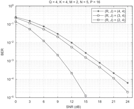
Performance of different STS schemes: In the first experiment, we consider a MIMO-CDMA downlink system with Q ¼4 users, K¼4 transmit antennas and M¼2 receive antennas. We consider three STS schemes with different stream-to-antenna allocation matrices fWðiÞg,
i¼1;2;3:
Wð1Þ¼G1111; Wð2Þ¼G211; Wð3Þ¼G22.
The code-to-antenna allocation matrix is the same for all the schemes and is given by
U¼G1111.
The parameters fJrg and fKrg, r¼1;. . .;R, characterizing these allocation matrices are summarized inTable 1. In scheme 1, there is no reuse of data streams and spreading codes across the transmit antennas. In scheme 2, the first data stream is spread twice across two antennas, while in scheme 3 both data streams are spread in the spatial domain across two antennas. According to Fig. 3, the performance improves when going from schemes 1 to 3.
Table 1
Transmit parametersfJrgandfKrgused in the STS schemes of Fig. 3
Scheme 1 Scheme 2 Scheme 3
fJ1;K1g f1;1g f2;2g f2;2g
fJ2;K2g f1;1g f1;1g f2;2g
fJ3;K3g f1;1g f1;1g –
The performance gain of scheme 2 over scheme 1 is certainly due to the spatial spreading of the first data stream contributing to an improved average performance. Scheme 3 offers the best performance by spatially spreading each data stream across two antennas. How-ever, it is important to note that such a performance improvement obtained by decreasing the number of data streams (and, consequently, by increasing the transmit diversity) comes at the expense of a reduction in spectral efficiency. For instance, the spectral efficiency is reduced by a factor of two when going from schemes 1–3. Recalling that QPSK modulation is used, we have SF¼2, 1.5 and 1 for schemes 1, 2 and 3, respectively.
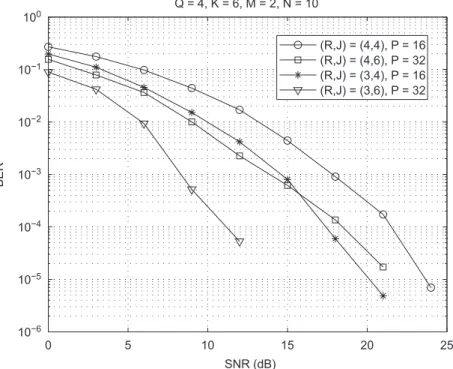
In the second experiment, we consider Q¼4 users,
K¼6 transmit antennas and M¼2 receive antennas. Note that this is a more challenging system configuration, where the number of receive antennas is much smaller than the number of transmit antennas/users. For this system configuration, we simulate four STS schemes with different pairs of allocation matrices fWðiÞ;UðiÞg,
i¼1;. . .;4:
fWð1Þ;Uð1Þg ¼ fG2211;G2211g,
fWð2Þ;Uð2Þg ¼ fG2211;G111111g,
fWð3Þ;Uð3Þg ¼ fG222;G2211g,
fWð4Þ;Uð4Þg ¼ fG222;G111111g.
The parametersfJrgandfKrg,r¼1;. . .;R, associated with
these allocation matrices are given inTable 2. We should note that the four schemes differ in the number of per-user data streams and spreading codes allocated for transmission. For schemes 1 and 2 the number of data streams per user isR¼4. On the other hand, for schemes
3 and 4 we have R¼3. Concerning the number of spreading codes/spreading factor, we haveJ¼4 andP¼
16 for schemes 1 and 3, andJ¼6 andP¼32 for schemes 2 and 4. The results are displayed in Fig. 4. Note that scheme 3 outperforms scheme 1. This performance gain can be justified as follows. FromTable 2, we can see that scheme 1 transmits four data streams over six antennas. Note that only the first and second data streams are spread across two transmit antennas ðK1¼K2¼2Þ, the
third and fourth data streams being transmitted by a single antenna. On the other hand, scheme 3 transmits three data streams over six antennas, i.e. all the three data streams are spread across two antennas ðK1¼ K2¼K3¼2Þ, thus benefiting from an average transmit
diversity gain of order two. The performance gain of scheme 3 w.r.t. scheme 1 is also related to the receiver capability in separating the transmitted signals, which is facilitated when fewer data streams are transmitted. The same comments are valid when comparing schemes 2 and 4. The difference is that these schemes useJ¼6 codes for transmission, while schemes 1 and 3 useJ¼4 codes only. In fact, the number of used codes explains the better 0 3 6 9 12 15 18 21 24
10−5
10−4
10−3 10−2
10−1
100
SNR (dB)
BER
Q = 4, K = 4, M = 2, N = 5, P = 16
(R, J) = (4, 4) (R, J) = (3, 4) (R, J) = (2, 4)
Fig. 3.Performance of different STS schemes forQ¼4,K¼4 andM¼2.
Table 2
Transmit parametersfJrgandfKrgused in the STS schemes of Fig. 4
Scheme 1 Scheme 2 Scheme 3 Scheme 4
fJ1;K1g f1;2g f2;2g f1;2g f2;2g
fJ2;K2g f1;2g f2;2g f1;2g f2;2g
fJ3;K3g f1;1g f1;1g f2;2g f2;2g
fJ4;K4g f1;1g f1;1g – –
performance of scheme 2 w.r.t. scheme 1, and of scheme 4 w.r.t. scheme 3 due to a higher code diversity for a fixed number of data streams (R¼4 or 3).
Comparison with the ZF-MUD receiver: In order to provide a performance reference for the proposed STS model using the ALS algorithm, we have simulated the Zero Forcing MUltiuser Detection (ZF-MUD) receiver, where all the data streams of all the users are jointly detected. The ZF-MUD receiver assumes perfect knowl-edge of all user channels, in contrast to the ALS-based receiver which performs a channel-blind detection. Using our notation, the ZF-MUD receiver consists in a single-step estimation of the symbol matrix as follows:
ST¼
HðqÞXD1ðCUÞW T
.. .
HðqÞXDPðCUÞW T
2
6 6 6 6 4
3
7 7 7 7 5
y XðqÞ1
.. .
XðqÞP
2
6 6 6 6 4
3
7 7 7 7 5
¼ ½ðCU HðqÞXÞWTyXðqÞ
1 .
Two STS configurations are chosen, in the first one we have ðR;J;KÞ ¼ ð3;4;4Þ with allocation matrices
fWð1Þ;Uð1Þg ¼ fG211;G1111g. In the second one, we have
ðR;J;KÞ ¼ ð2;3;3Þ with allocation matrices fWð2Þ;Uð2Þg ¼ fG21;G111g. Note that these system configurations are
similar w.r.t. the transmission of the first and second data streams (fJ1;K1g ¼ f2;2g and fJ2;K2g ¼ f1;1g for both
schemes). The difference is that the first system config-uration has an additional transmit antenna which is used to transmit a third data stream. According toFig. 5, there is a performance gap between ALS-based receiver and the
ZF-MUD receiver in both configurations. Considering, for instance, the first configuration, we can observe a SNR gap around 5 dB between both receivers for a BER¼102. This is an expected result, since the proposed algorithm works with no knowledge about the channel while ZF-MUD assumes perfect channel knowledge. Note also that the second configuration outperforms the first one. In fact, the second configuration transmits less data streams than the first one, thus improving the signal separation performance for both receivers.
Comparison with competing STS schemes: In [5], a transmit diversity STS scheme was proposed for the downlink of a DS-CDMA system. For two transmit antennas and one receive antenna, it achieves the same spatial diversity gain as the Alamouti code[26]with the advantage that no extra spreading codes are required. Here, we compare this classical scheme with the proposed one considering a single-user transmissionðQ ¼1Þwith
R¼2,M¼K¼2 andP¼2. Orthogonal Walsh–Hadamard codes were used in both schemes. It should be noted that perfect channel knowledge is assumed for the STS scheme of[5], which leads to the best performance this scheme can achieve. In contrast, the proposed STS scheme uses ALS-based blind detection. The results are depicted in Fig. 6. Both schemes provide very close performance. Note that the gap is around 1 dB for a BER¼102.
We now compare the proposed STS scheme with the multilayered STS scheme of[6]. In this scheme, the serial input stream is divided into multiple data streams, or ‘‘layers’’, each one being spread by a unique STS sequence. At the receiver, a linear MUD receiver is used to recover all the layers under the assumption of perfect channel knowledge. Recall that the proposed STS scheme assumes
0 5 10 15 20 25
10−6
10−5
10−4
10−3
10−2 10−1
100
SNR (dB)
BER
Q = 4, K = 6, M = 2, N = 10
(R,J) = (4,4), P = 16 (R,J) = (4,6), P = 32 (R,J) = (3,4), P = 16 (R,J) = (3,6), P = 32
a channel-blind detection. The fixed system parameters are K¼4, Q¼J¼4 and R¼1. In order to keep the spectral efficiency at the same value, we choose P¼16 and 16-QAM for the proposed STS scheme, while P¼8 and 4-QAM are used in the STS scheme of[6]. The results are shown inFig. 7 consideringM¼2 receive antennas. We can see that the proposed scheme significantly
outperforms the multilayered STS scheme for SNR values higher than 15 dB.
6. Conclusion
In this paper, we have presented a new constrained tensor model for the downlink of a MIMO-CDMA system
0 3 6 9
10−5
10−4 10−3
10−2
10−1 100
SNR (dB)
BER
Q = 1, K = 2, M = 2, N = 5, P = 2
Proposed scheme (R,J) = (1,2) STS scheme of [5]
Fig. 6.Performance comparison between the proposed STS scheme and the STS scheme of [5].
0 3 6 9 12 15 18
10−5
10−4
10−3
10−2
10−1
100
SNR (dB)
BER
Q = 2, M = 3, N = 10, P = 8
ALS, (R,J,K) = (3,4,4) ALS, (R,J,K) = (2,3,3) ZF−MUD, (R,J,K) = (3,4,4) ZF−MUD, (R,J,K) = (2,3,3)
Fig. 5.ALS-based receiver (channel-blind) vs. ZF-MUD receiver (channel knowledge). A.L.F. de Almeida et al. / Signal Processing 88 (2008) 2403–2416
with multiuser spatial multiplexing. We have proposed a complete parametrization for the stream and code alloca-tion matrices along with new design constraints. Based on these design constraints, a codebook of feasible STS schemes with guaranteed blind symbol recovery can be derived for a given number of data streams, spreading codes and transmit antennas. We have presented some design examples for 2, 3 and 4 transmit antennas. Bit-error-rate performance of some STS schemes has been evaluated using a two-stage receiver. Assuming that the spreading codes are known at the receiver, multiuser interferences are first eliminated and then the users’ symbols and channels are jointly and blindly estimated using the ALS algorithm. We have also compared our STS schemes with some competing schemes. Practical per-spectives of this work include variable per-user STS structures (i.e. users with different allocation matrices). We are currently investigating performance-oriented de-signs for the allocation matrices to cope with the user selection problem.
References
[1] G.J. Foschini, M.J. Gans, On limits of wireless communications when using multiple antennas, Wireless Pers. Comm. 6 (3) (1998) 311–335.
[2] H. Huang, H. Viswanathan, G.J. Foschini, Multiple antennas in cellular CDMA systems: transmission, detection, and spectral efficiency, IEEE Trans. Wireless Comm. 1 (3) (2002) 383–392. [3] S. Sfar, R.D. Murch, K.B. Letaief, Layered spacetime multiuser
detection over wireless uplink systems, IEEE Trans. Wireless Comm. 2 (4) (2003) 653–668.
[4] L. Mailaender, Linear MIMO equalization for CDMA downlink signals with code reuse, IEEE Trans. Wireless Comm. 4 (5) (2005) 2423–2434.
[5] B. Hochwald, T.L. Marzetta, C.B. Papadias, A transmitter diversity scheme for wideband CDMA systems based on space–time spread-ing, IEEE J. Selected Areas Comm. 19 (1) (2001) 48–60.
[6] B.K. Ng, E. Sousa, Space–time spreading multilayered CDMA system, in: Proceedings of the GLOBECOM, vol. 3, 2000, pp. 1854–1858. [7] R. Doostnejad, T.J. Lim, E. Sousa, Space–time spreading codes for a
multiuser MIMO system, in: Proceedings of the 36th Asilomar Conference on Signals, Systems and Computers, Pacific Grove, USA, 2002, pp. 1374–1378.
[8] R. Doostnejad, T.J. Lim, E. Sousa, Space–time multiplexing for MIMO multiuser downlink channels, IEEE Trans. Wireless Comm. 5 (7) (2006) 1726–1734.
[9] N.D. Sidiropoulos, G.B. Giannakis, R. Bro, Blind PARAFAC receivers for DS-CDMA systems, IEEE Trans. Signal Process. 48 (3) (2000) 810–822.
[10] R.A. Harshman, Foundations of the PARAFAC procedure: model and conditions for an ‘‘explanatory’’ multi-mode factor analysis, UCLA Working Papers in Phonetics, vol. 16, 1970, pp. 1–84.
[11] N.D. Sidiropoulos, G.Z. Dimic, Blind multiuser detection in WCDMA systems with large delay spread, IEEE Signal Process. Lett. 8 (3) (2001) 87–89.
[12] A. de Baynast, L. De Lathauwer, De´tection autodidacte pour des syste`mes a` acce`s multiple base´e sur l’analyse PARAFAC, in: Proceedings of XIX GRETSI Symposium on Signal and Image Processing, Paris, France, 2003.
[13] A.L.F. de Almeida, G. Favier, J.C.M. Mota, PARAFAC models for wireless communication systems, in: Proceedings of the Interna-tional Conference on Physics in Signal and Image Processing (PSIP), Toulouse, France, 2005.
[14] A.L.F. de Almeida, G. Favier, J.C.M. Mota, PARAFAC-based unified tensor modeling for wireless communication systems with applica-tion to blind multiuser equalizaapplica-tion, Signal Processing 87 (2) (2007) 337–351.
[15] D. Nion, L. De Lathauwer, A block factor analysis based receiver for blind multi-user access in wireless communications, in: Proceed-ings of the ICASSP, Toulouse, France, 2006.
[16] N.D. Sidiropoulos, R. Budampati, Khatri–Rao space–time codes, IEEE Trans. Signal Process. 50 (10) (2002) 2377–2388.
[17] A. de Baynast, L. De Lathauwer, B. Aazhang, Blind PARAFAC receivers for multiple access-multiple antenna systems, in: Proceedings of the VTC Fall, Orlando, USA, 2003.
[18] A.L.F. de Almeida, G. Favier, J.C.M. Mota, Space–time multiplexing codes: a tensor modeling approach, in: IEEE International
Work-0 5 10 15 20 25
10−5 10−4 10−3
10−2
10−1
100
SNR (dB)
BER
K = 4, M = 2, N = 10
Proposed scheme STS scheme of [6]
shop on Signal Processing Advances in Wireless Communications (SPAWC), Cannes, France, 2006.
[19] A.L.F. de Almeida, G. Favier, J.C.M. Mota, Tensor-based space–time multiplexing codes for MIMO-OFDM systems with blind detection, in: IEEE International Symposium on Personal Indoor and Mobile Radio Communications (PIMRC), Helsinki, Finland, 2006. [20] A.L.F. de Almeida, G. Favier, J.C.M. Mota, Constrained tensor
modeling approach to blind multiple-antenna CDMA schemes, IEEE Trans. Signal Process., 2008, to appear.
[21] I. Chih-Lin, R.D. Gitlin, Multi-code CDMA wireless personal communication networks, in: Proceedings of the International Conference on Communications, ICC, Seattle, WA, 1995, pp. 1060–1064.
[22] S.J. Lee, H.W. Lee, D.K. Sung, Capacities of single-code and multi-code DS-CDMA systems accommodating multiclass services, IEEE Trans. Vehic. Technol. 48 (2) (1999) 376–384.
[23] Third generation partnership project, Universal mobile telecommu-nications system (UMTS); spreading and modulation (FDD). Technical Report ETSI TS 25.213 V6.2.0.
[24] R.W. Heath, D.J. Love, Multimode antenna selection for spatial multiplexing systems with linear receivers, IEEE Trans. Signal Process. 53 (8) (2005) 3042–3056.
[25] D.J. Love, R.W. Heath, Multimode precoding for MIMO wireless systems, IEEE Trans. Signal Process. 53 (10) (2005) 3674–3687. [26] S. Alamouti, A simple transmit diversity technique for wireless
commu-nications, IEEE J. Selected Areas Comm. 16 (8) (1998) 1451–1458. A.L.F. de Almeida et al. / Signal Processing 88 (2008) 2403–2416
![Fig. 6. Performance comparison between the proposed STS scheme and the STS scheme of [5].](https://thumb-eu.123doks.com/thumbv2/123dok_br/15267745.540653/12.816.182.640.86.458/fig-performance-comparison-proposed-sts-scheme-sts-scheme.webp)
![Fig. 7. Performance comparison between the proposed STS scheme and the multilayered STS scheme of [6].](https://thumb-eu.123doks.com/thumbv2/123dok_br/15267745.540653/13.816.174.641.85.462/fig-performance-comparison-proposed-sts-scheme-multilayered-scheme.webp)
