Development of a WormCAD using Parametric
De-sign Approach
Olayinka Oluwole Agboola, Peter Pelumi Ikubanni, Adeolu Adesoji Ad-ediran, Rotimi Adedayo Ibikunle, Bamidele Temitope Ogunsemi
Gears as power transmission devices are capable of changing the speed, torque, and direction of a power source and are considered to be one of the most important devices used in many types of machinery owing to their durability and higher power transmission efficiency. Worm gears as a type of gear are widely used for transmitting power at high velocity ratios between non-intersecting shafts. Worm gears are very useful in machine design but its design requires a lot of design as-sumptions and calculations. To achieve a rapid design devoid of errors, there is need to have a customized computer program capable of de-signing worm gears using standardized design equations; and that is what WormCAD stands for. The software was designed using JavaScript programming language and the Node.js platform. The WormCAD was tested to be accurate, faster and convenient hence it will be a viable software to be used by worm gear designers.
Keywords: Worm gear, CAD, Design, Power transmission, Software
1. Introduction
After generation of power from one part of a machine or the other, there is always a need to transfer such a power (torque) to the other element(s) of a ma-chine. Different power transmitting devices such as belt drives, chain drives, gear drives could be used for this purpose, but gears are more preferable to others be-cause of their ability to achieve definite velocity ratio (Akinnuli et al., 2015). Ac-cording to Khurmi and Gupta (2005), a gear is defined as a rotating machine ele-ment having cut teeth (or cogs) which mesh with another toothed part in order to transmit torque. Gear devices are capable of changing the speed, torque, and di-rection of a power source and are considered to be one of the most important de-vices used in many types of machinery owing to their durability as a power trans-mission devices and higher power transtrans-mission efficiency of up to 98% Hamrock et al., 2006).
ANALELE UNIVERSITĂŢ
II“EFTIMIE MURGU” REŞIŢA
According to the position of the axes of the shaft, gears can be classified as: Intersecting shafts- bevel gears; Non-intersecting and skew shafts- worm gears, hypoid gears; and Parallel shafts- spur gears, helical gears. As reported by Khurmi and Gupta (2005) gears have been in existence for a very long time. The first worm gear was produced in 1912 and its introduction in controlling the rudder of a ship was seen as a major development in the field of marine engineering.
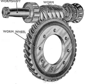
Worm gears are widely used for transmitting power at high velocity ratios be-tween non-intersecting shafts that are generally, but not necessarily at right an-gles. The worm gear is mostly used as a speed reducer, which consists of a worm and a worm wheel or gear. The worm (the driver) is usually of a cylindrical form having threads of same shape as that of an involute rack. The worm wheel or gear (the driven member) is similar to a helical gear with a face shaped to suit the shaped of the worm. The worm is generally made of steel while the worm gear is made of bronze or cast iron. Worm gears are very use in engineering and machine design, some of its applications are found in: Elevator/Lifts; Gates and conveyor belts; Torsen differentials; and the differential gearing which protects a vehicle against rollback
Figure 1. Typical worm gear
Computer Aided Design (CAD) involves the use of computer in modification, analysis or optimization of design (Antoniadis, 2012). Computer technology ad-vancement also gains application in engineering designs. Gear design using com-puter aided approach is not left out in this development. Quite numbers of works have been done in gear design using computer aided approach for simulation or software development.
in spur gear design but the developed template has limitations that it can only be used in places where the gears are incorrect. When the gear design has modifica-tions such as addendum, dedundum or proturberance and so on, it would further complicate the template modeling. Venkatesh et al. (2010) worked on the design, modeling and manufacturing of helical gear. However, manual long hand calcula-tions were employed and the design was solely meant for helical gear. This design approach was later improved upon in 2014 by Venkatesh, and Murthy through the introduction of structural analysis using ANSYS. Tanvirkhan and Amit (2015) gave the review of design, modeling and stress analysis of high speed helical gear according to bending strength and contact strength using AGMA and ANSYS. To show that CAD is applicable to other types of gear, [9] gave a method of spiral bevel gear tooth contact analysis performed in CAD. They focused mainly on the analysis of teeth contact but Akinnuli et al., (2008) gave a comprehensive design of bevel gears using a BevelCAD (Software for designing Bevel gears). They claimed that the software developed was tested and performed satisfactorily. Also, the software is meant for the design of Bevel gears alone. Extensive literature reveals that there are multi-purpose gear design softwares like KIMOS but there is no specific, customized software for the design of Worm gears. The design of worm gears involves a lot of assumptions and calculations which can make the designer/engineer to commit some errors. To avert such error(s) and to make the interface to be more user-friendly, a WormCAD software that is meant for the design of only worm gears was developed. This will reduce effort employed in routine manual calculation hence saving time in designing worm gears. Standard gear design equations and assumptions were used in developing the software.
2. Software Design Process
Software design is sub-divided into four segments (Adejuyigbe, 2002) which include: Analysis; Algorithm design; Coding; Testing.
2.1. Analysis
The key to well-designed software is analysis, as it reduces coding difficulties. Proper and accurate Analysis helps in selection of the most appropriate data structure. The software application was able to accept the input parameters and transformed into the required output by utilizing sets of mathematical relations.
2.2 Algorithm Design of Worm Gear
I Declare constants for different materials - Allowable static strength
- Flexural endurance strength Select materials and tooth forms II Select materials
Select number of start or thread
III Dimension of worm
Enter the reduction or velocity ratio Determine the lead angle( )
Enter the distance between the shaft Determine the normal lead from
= ( + ) (1)
Select the number of starts or threads from the velocity ratio Determine the axial pitch on the worm
Calculate module m for m = (2)
Select the standard module from the calculated module Calculate the following;
Axial pitch Pa of the threads on the worm
= (3)
Axial lead of the threads on the worm L
L = × n (4)
Normal lead of the threads
= l (5)
Centre distance x
x = ( + ) (6)
Pitch circle diameter of the worm Dw
= (7)
Determine the number of teeth on the worm TG
= n × V.R (8)
Length of threaded portion or face length of the worm Lw
= (4.5 + 0.02 ) (9)
Depth of tooth h
h = 0.623 (10)
Addendum a
a = 0.286 (11)
Outside diameter of the worm Dow
= + 2 (12)
IV Design of worm gear
Pitch circle diameter of the worm gear DG
m (13)
= + 0.8903 (14) Throat diameter DT
= + 0.572 (15)
Face width b
b = 2.15 + 5 (16)
V Design of the worm shaft = diameter of the worm shaft Torque on the worm gear shaft
T = (17)
Torque acting on the worm shaft
= (18)
VI Tangential force on the worm WTW
= (19)
Axial force on the worm
=
(20) Radial force on the worm WR
= (21)
Bending moment due to radial force
Radial force = (22)
Bending moment due to axial force in the vertical plane
= (23)
Total bending moment in the vertical plane MI
= + (24)
Bending moment due to tangential force in the horizontal plane M2
= (25)
Resultant bending moment on the worm shaft Mworm
= (26)
Twisting moment on the worm shaft
= (28) Compressive stress on the shaft due to axial force
= (29)
Maximum shear stress
= (30)
If is less than , then the design of shaft is safe.
VI Tangential Load
Determine the speed of the worm gear in rpm = speed of worm gear
V.R. = or = (31)
Therefore torque transmitted,
T = (32)
Tangential load acting on the gear
=
Pitch line or peripheral velocity of the worm gear,
v = (33)
Where velocity factor is,
Tooth factor y = 0.154 - (for 200 ) , 0.124 - (for 14.50) (34) Designed tangential load
= ( ) b.
If , the design is safe from the standpoint of tangential load. VII Dynamic Load
WD is Dynamic load
= (35)
If , the design is safe from the standpoint of dynamic load.
VIII Static Load / Endurance Strength
If the design is safe from the standpoint of static load / endurance strength.
IX Wear
= .b. k (37)
If , the design is safe from the standpoint of wear.
X Heat Dissipation
Determine the rubbing velocity Vr
= (38)
Coefficient of friction µ
µ = 0.025 + (39)
Angle of friction
= (40)
Efficiency of worm gearing
= (41)
Percentage overload
= 1.25P (1- η) (42)
Projected area of worm
= )2 (43)
Projected area of worm gear
= ( )2 (44)
Total area of projection A
A = (45)
Heat dissipating capacity
= A( ) (46)
= , if within safe limits of 270 to 380C, then the design is safe from the standpoint of heat.
XI Worm Gear Shaft
= diameter of worm gear shaft
Bending moment due to axial force on the worm gear Y
Y = (47)
Bending moment due to radial force on the worm gear
Total bending moment in the vertical plan
= Y + Z (49)
Bending moment due to tangential force in the horizontal plane M4
= (50)
Resultant bending moment on the worm gear shaft
= (51)
Equivalent twisting moment
= (52)
= (53)
= (54)
Maximum Shear stress
= (55)
Coding
The algorithm above was used to develop the software (Worm CAD).This was made possible by transforming the required formulas and data of worm into a set of instruction codes. The codes written could validate the user inputs by giving the user the necessary information as output. The software was designed using JavaScript programming language and the Node.js platform. The Node.js platform is an open-source, cross-platform runtime environment for developing Web applications. Node.js applications can run on Mac OS X, Microsoft Windows, Nonstop and UNIX servers
2.4 Testing
WormCAD was tested and validated with an example from a Machine Design textbook by Khurmi and Gupta [2]
A worm and a worm gear with both made of steel (BHN 250) and phosphor bronze respectively were designed using the developed WormCAD software. The gear to be used has the following input parameters.
Tooth form – 20o involute Number of start or thread – 4 Speed reduction/V.R – 12:1
All the above input parameters were fed into the Design interface of the software as shown in figure 2
Figure 2. Input parameters for Worm CAD
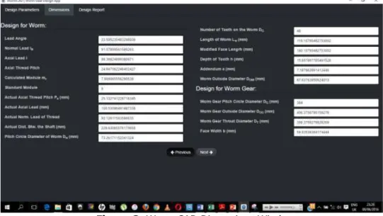
Running the software, it displayed the calculated module which was rounded off to the nearest standard module. After supplying the value of standard module, and on clicking on next, it displayed the various dimensions as shown in figure 3
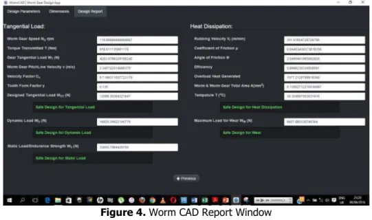
Clicking on the next button again, another window as shown in Figure 4 was displayed which gave report about the status of the design (either safe or unsafe)
Figure 4. Worm CAD Report Window
3. Results and Discussions 3.1 Results
The software was able to generate the following key parameters: Module, Pitch circle diameter of worm, Number of teeth on the worm, Length of tooth of the worm, Worm outside diameter, Pitch circle diameter of the worm gear, Worm gear outside diameter, Face width, Torque transmitted, Gear tangential load; and gave the following reports about the status of the design (either Safe or Unsafe): Tangential load, Dynamic load, Static load, Heat dissipation, and Wear
3.2 Discussions
Comparing the manually calculated results with the WORM CAD results, the following observations were made:
Accuracy in calculations
The software calculations are believed to be more accurate because it uses uniform approximation in all its results. Hence, negligible differences in the results were obtained between WormCAD software and manual calculation..
Reduction in errors
Time management
The software minimizes the time used for computation. The WORM CAD calculations only take seconds to generate the results with precision. This ensures time management which is an advantage over manual computation.
Suggesting design conditions to designers
The software suggests the physical condition of the designed worm gear using the computed result. These remarks help designers to achieve better designs.
4. Conclusion
Gears are used in the transmission of motion and power from a machine element to the other. Standard design equations were used in developing the codes for the WormCAD which is an easy-to-use worm gear design software. The benefits of the WormCAD over the routine manual method have been highlighted and discussed. It is of no doubt that this WormCAD will help designers achieve better designs when designing worm gears.
References
[1] Akinnuli B.O., Agboola O.O., Ikubanni P.P., Parameters Determination for the Design of Bevel Gears Using Computer Aided Design (Bevel CAD), British Journal of Mathematics & Computer Science9(6):537-558, 2015. [2] Khurmi R.S., Gupta J.K., Textbook on machine design, Fifth Ed., S.
Chand Eurasia Publishing House (PVT.) LTD, Ram Nagar, New Delhi, 2005.
[3] Hamrock B.J., Steven R. S, Bo J.O., Fundamentals of machine ele-ments, Eight Ed. McGraw-Hill, New York, USA. 2006.
[4] Antoniadis, Gear skiving–CAD simulation approach, Computer-Aided Design, 44 611-616, 2012.
[5] Babu V. S and Tsegaw A. A., Involute Spur Gear Template Develop-ment by Parametric Technique Using Computer Aided Design, An Interna-tional Multi-Disciplinary Journal, Ethiopia 3(2): 415-429, 2009.
[6] Venkatesh B., Kamala V., Prasad A.M.K., Design, Modeling and Manu-facturing of Helical Gear, International Journal of Applied Engineering Re-search, 3(2): 233-241, 2010.
[7] Venkatesh J., Murthy S.N., Design and Structural Analysis of High Speed Helical Gear Using Ansys, International Journal of Engineering Re-search and Applications, 2(3):215-232, 2014.
[9] Bartłomiej S., Adam M., Method of spiral bevel gear tooth contact analysis performed in CAD, Aircraft Engineering and Aerospace Technol-ogy, 85(6): 467-74.2013.
[10] Adejuyigbe S.B., CAD/CAM for Manufacturing. Engineering Textbook. Publication for Universities, Polytechnics, Business and Technical Colleges, TopFun Publications, Akure, Nigeria. 2002.
Addresses:
• Agboola O. O, Department of Mechanical Engineering, College of Sci-ence and Engineering, Landmark University Omu-Aran, Kwara state, Nigeria. [email protected]
• Ikubanni P.P, Department of Mechanical Engineering, College of Sci-ence and Engineering, Landmark University Omu-Aran, Kwara state, Nigeria. [email protected]
• Adediran A. A, Department of Mechanical Engineering, College of Sci-ence and Engineering, Landmark University Omu-Aran, Kwara state, Nigeria. [email protected]
• Ibikunle R. A, Department of Mechanical Engineering, College of Sci-ence and Engineering, Landmark University Omu-Aran, Kwara state, Nigeria. [email protected]