A Network and Repository for Online
Laboratory, based on Ontology
Hamadou Saliah-Hassane Senior IEEE
TELUQ Université du Québec LICEF Research Center
saliah@teluq.ca
Raúl Cordeiro Correia Escola Superior de Tecnonologia de
Setúbal
Instituto Politécnico de Setúbal raul.correia@estsetubal.ips.pt
José Manuel Fonseca Faculdade de Ciências e Tecnologia
Universidade Nova de Lisboa Caparica, Portugal
jmf@uninova.pt
Abstract — Our propose is to build a network of virtual laboratories and also use it as a global repository of online laboratory’s and experiences.
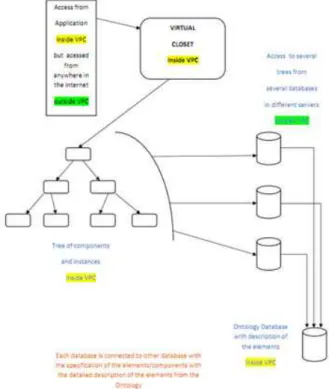
This set of virtual and online laboratories can be “stored” in an “virtual closet”, and also the system will allow us to build new experiences and online laboratories, and store them is this “virtual closet”.
With the drawing of this new standard we pretend define methods for storing and retrieving learning objects for remote laboratories. The objective of this standard is also define methods for linking learning objects to design and implement smart learning environments for remote online laboratories.
The objects defined by this standard are, for example, interfaces for devices connected to user computers over computers networks and the devices themselves. They are also learning scenarios or collaboration tools for communications necessary to conduct an activity of practical online laboratory work, they will allow to design and implement mechanisms that make smart learning environment formed by the ad hoc aggregation of learning objects taking always into account the pedagogical context for their use.
This will allow to easy design and implement the pedagogically driven remote laboratory environment and experiments as also is learning environments.
The experiences and laboratories are build using the parts and separate components that we have in a separate “virtual closet” with parts, components, and already build experiences.
To build this complex network we need to find a system that supports effectively this structure. This probably will be a enormous database of v-labs and independent elements, where will be possible sometimes to “recycle” some of the elements. For this structure we propose an Ontology because it allows to “re-use” the same element several times in many experiences, and provide a very detailed description of each kind of element through is classes and sub-classes.
Index Terms— V-labs, Virtual Labs, E-learning, CMS, Ontology, Remote Laboratory, distributed instrumentation.
I. INTRODUCTION
Due to the emergence of new technologies making data networking possible, there has been a growing demand to utilize distributed systems for telemetering, remote monitoring and remote control purposes. These systems have a high application potential in many areas, such as on-line training and collaborative work for
geographically dispersed teams. The research program involves between other related aspects with remote laboratories, designing and modeling a centralized remote laboratory brokerage system. More specifically, our work is has is focus also on developing intelligent and user friendly adaptive interfaces [32] required by those involved in remote laboratory environments, depending on the role each has to play during a laboratory session [33]. These interfaces provide individuals, either on site or geographically dispersed, with virtual access to the real tools and/or equipment they will need to use either separately or as part of a team. Our goals would be to: a) suggest scenario models and tools for building interfaces for geographically dispersed users, while meeting the norms and standards for the learning objects; b) suggest mechanisms to allow for storing, tracking and retrieving the interfaces, interoperable resources and the learning objects;
c) suggest on-line laboratory management models allowing for sharing the human and physical resources of various institutions. As part of an inter-institutional remote laboratory environment, this management and organization of tutorial sessions will not be possible unless one utilizes a remote assistance system, along with optimization methods and operational research, for planning, allocating resources right on schedule, organizing and managing tasks based on pedagogical scenarios in a synchronous mode [31].
Remote laboratories are learning systems which allow users to learn by carrying out practical work over computer networks. This system integrates various types of resources which are generally found in telelearning systems such as learning objects and communication tools. However, remote laboratories can use dynamic learning objects to provide users with remote access to laboratory devices in real time. Moreover, the system resources can be integrated into a multi-environment platform: the environments of the learner, the tutor, the administrator and the instructional designer. These environments are designed especially with the user role in mind.
A Pedagogical model
Figure 1 – Pedagogical model [22]
To develop this environment is necessary to define a “Pedagogical Model” and also a “Media Model”. The pedagogical model, represented with the same graphical symbols using MOT [22], describes the learning process based on the knowledge model. It illustrates how the laboratory activity and procedures are conducted, as well as the interactions amongst the actors and objects. It exhibits the fact that objects are distributed, shared by multiple learners regardless of their remote geographical locations. Upper figure illustrates the pedagogical model. A Media model
The media model describes the nature of the teaching materials previously selected with the knowledge and the pedagogical models. Based on these models we can easily identify the learning objects and eventually the graphical user interfaces needed to complete a laboratory activity. MISA[22] is helpful in that it suggests the production of a document with the critical attributes of all objects, taking into account the specific characteristic which is the synchronous use of the telelaboratory learning objects in a collaborative environment.
Since the telelaboratory learning objects are specific in that they should map to the corresponding networked devices to work properly, an important issue raises to that extent. In fact, learning objects must be compatible with standards such as the meta-data provided by the IEEE LOM [23], yet the latter is not sufficient and indeed there is a need to refine the relationships expressed among the objects and eventually other required resources likewise the ones needed in the course of telelaboratories. IMS LD[22] suggests a meta-model to describe relationships between objects through building a framework that defines the structure for the content and the behaviour of the different types of learning objects [24].
The main problem that we want to solve is to find a structure that allow us to define a efficient and logical database that is completely able to support our virtual labs network.
This structure must permit to classify all the components and parts used in our experiences, and allow us to go get this elements/objects in a “Virtual Closet”, that we must
build and define, prior to anything else. We defend that this structure is an Ontology.
This “Virtual Closet” will be the base of our system to build the virtual experiments. And the structure that supports this “closet” ,must allow to use and define several instances of the same object that we go to use in different experiments that can exist and run at the same time.
One of the most important points to develop in this project is the “user interface” that will be used by all users of the system.
So in this point we will try to make and discuss a definition of user interface integration.
To integrate this user interface in all the Lab@DER and EURONET-LAB system, it is important to define logically and technically how we will make this integration.
So, the way we choose, is first to see what is now the “State of the Art” in this matter.
So, after consulting several documents in that area, we think that the most important point to see and study is the “Application Integration” with the developed ontology and the other components of the system that we will choose.
The application integration of the user interface is one of the most used techniques to connect the user with software applications.
There are several kinds of approach to solve this issue. In this point we go discuss the definition of “user interface integration”.
One of the most accepted models of integration interface is the model of Fowler [7],[10], and this model define the three main layers:
1 – The source layer
2 – The business logic layer (or domain layer) 3 – Presentation layer
Several authors derived from this classification. This leads to the simplest model of system integration;
- An integration layer can be placed in the top of each one of the layers, facilitating by this way the application integration in the 3 layers: - Data layer (source layer)
- Business layer - Presentation layer
To better understand the figure 2 we go present a little resume of the classification criteria for some authors:
- Amsden[8] introduces a variation of integration; one application may “involve” another, i.e. start it via access to the underlying operation system.
strategies of integration on the UI components and also make changes on the screen handling layer. The classification of levels can be shown in the following diagram of levels that show us the classification of levels made by several authors:
Figure 2 – Classification of levels [10]
As main concept, Linthicum [10] distinguishes two types of integration on the business logic level:
- Application interface integration - Method integration
Let’s see its differences with more detail:
- The application interface integration means that the application call methods from another one.
- Method integration implies the exchange of models and also more complex patterns of
interaction between applications, going beyond simple method calls [10].
Other authors, Benatallah Nezad [13] provide an even finer-grained distinction of integration business layer. This comes besides the distinction of Linthicum’s between application interface (called “function integration” by the authors). In this case they introduce the need for addictionally coordinating the message exchange itself (called basic coordination) as well as policies, such as privaty policies and quality of service agreements between systems. Also the authors introduce the communication layer as another layer of integration, thereby stressing that when integration distributed applications, the communication protocol heterogeneities must be overcome [14].
We must also take in consideration the main advantages and benefits of “Application Integration” on the “User Interface Layer”.
There are two main benefits for performing application integration o the user interface level:
- Increasing the usability of software systems - Reducing development efforts for those software
systems.
We can see these benefits from two points of view: - From the user, the end’s user
- From the software engineer
From the end user point of view, we can say that any system that is integrated on a deeper level than the user interface, will come with an individually developed user interface [15] .
So the user will be confronted with a new unfamiliar user interface that requires time to the user to learn how to use this interface.
On the other hand, if we have a simple interface system the user easily learn how to work with the interface and is easier to use and doesn’t require learning and adaptation time from the user.
From the software engineers point of view, reusing an existing interface, as opposed to developing a new interface from the “zero point” means saving time and having less programming work.
It’s important have in mind that the user interface is normally the most expensive part of a software system. The portion of development effort dedicated to the user interface system in a project goes from 50% to 70% [17] of the total development effort.
In resume we can say that without an approach for integration of the user interface level the degree of reuse will never be higher than 50%. If we use UI integration, this action can therefore reduce development efforts of integrated software systems drastically.
Another very important aspect of the project to consider is; what are the requirements and challenges of Application Integration on the User Interface layer. This application integration on the UI layers take us to some challenges. About these challenges [15] is possible to enumerate five requirements for UI integration approaches:
2. Definition of a model and language for specifying the integration.
3. Create a support system for interaction and communication among the components.
4. Definition of a mechanism for visualizing the individual UI components.
5. Development of a mechanism for component discovery and binding.
A framework for the user interface integration has to have access to components to integrate in the ontology. Also is necessary to define a common model for those components, because is this model that will define how to access and control each component in the necessary actions to develop.
Typically, if we use a API, these components are API components. These API can be a high-level API, working at the level of business objects or, in another approach, can be a low-level API where the UI entities can be considered as buttons [15],[10].
Normally API’s at both levels are very useful as way to facilitate meaningful user interface integration. For integrating the user interface components, the developer has to specify coordination of the different components and also, the kind of relations that exists among them. This can be done in any general purpose programming language (C++ or Java) or in specialized languages. To implement interactions between components, some mechanisms for communication between components has to be provided. This can be a message exchange facility, event-based communication, etc. Communication between components can be performed either directly or centrally mediated [15],[10]. As user interface programming itself is most often event-oriented but is normal too the use of event-based communication for UI integration as well [16]. In an integrated UI, the individual application user interface components have to be displayed on the screen. The framework can either split and delegate the display to individual components or performed a unified display, e.g. based on markup as HTML. The last issue is the discovery and binding of components. The most common solution applies when the set of applications to integrate is not fixed at the time when the development code of the system is built. In this case the components can be registered, for example in an online repository, and then sought, found and bound when necessary at run-time.
The work already done to build this system was the project and drawing of the system, and also the definition of the main branches and elements of the ontology to use. We use Protégé Software as a tool to draw our ontology. So the definition of superclasses, sub-classes, and all the hierarchy is already build.
Also is already defined the concepts for each class build and also the properties of this concepts, also called is restrictions.
The contribution of this paper is explain and justify why , in our opinion, the better solution to implement this structure is an Ontology, and also define, and build all the objects and elements that we need in our system.
So we start to make an introduction, where we explain how to build an ontology, and what are the rules and steps that we must follow to correctly build the ontology we want to implement.
We can define an Ontology as:
“A Ontology defines a common vocabulary for researches and someone who need to share information in a domain”. [1]
Ontologies are widely used in integration of application scenarios, most of the times in the data and business logic level.
In a frequently cited article “Ontologies: Principles, Methods and Applications”, [18], point the usefulness of ontologies for promote inter-operability between IT systems.
The ontologies are proposed as a mean for “inter-lingua” for information exchange between applications.
The word “ontology” has its origin in the greek words: ο
οο
οννννττττοοοοξξξξ (“being”) and λολλλοοογγγγοοοξοξξξ (“theory” or “science”). So, ontology is “being theory” or “being science”, in fact it is a sub-area of philosophy that deals directly with the question of what existence actually is, and also it makes several categorization and organization of the existing things at a particular domain.
In computer science, “Ontology” is a formal model of a knowledge domain.
In philosophy area, ontology is used as singular word and refers a field of study, the computer science typically deals with many and various “ontologies” that are “formal models of a domain”, but for the same domain can exist more than one model.
Definition of Ontology:
There is a variety of definitions for ontologies in computer science:
Gruber [10],[19] says: “An ontology is an explicit specification of a conceptualization”.
Guarino and Giaretta [10],[20] presents a more detailed definition as: “An ontology is a logical theory which gives an explicit, partial account of a conceptualization”. But Guarino [10],[21] defines an ontology as: “A set of logical axioms designed to account for the intended meaning of a vocabulary”.
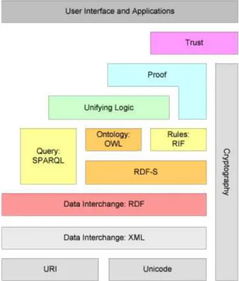
The authors outlined a new web semantic which was not made up of texts that could only be understood by humans, but of information that could be processed by intelligent software’s agents.
Figure 3 – The semantic webstack (Berners-Lee,2009,p.14)
The technological foundations on which the semantic web languages are built are the general-purpose eXtensible Markup Language, XML [10].
Next figure shows the 200 large datasets which are currently available as linked data.
Figure 4 – Aspect of the linked open datacloud .
Some rules can be used to express additional axioms that most ontology languages do not foresee. In the semantic web stack, various rule interchange formats to express rules defined with different individual rule languages, such as the Semantic Web Rule Language SWRL or the Rule Markup Language Rule ML [10]. Those rule languages allow for more flexible definitions than property chains in OWL2.
The Rule Interchange Format RIF provides an abstraction from those rule languages which is based in formal logic. It can be seen as an instantiation of the unified logic layer [10].
Query Systems:
To query the information contained in the semantic web or defined in RDF, ontologies and rules, various languages have been proposed, as we can see in the surveys made by Hease and others authors [10].
The query languages that were widely accepted for the ontologies are in RDF-based documents [10] are:
- SQL
- SPARQL
Apart from languages standardized or recommended by the World Wide Web Consortium, there are others that are used both in industry and universities.
The F-Logic is one of the most often used of these languages [10]. F-Logic which integrates ontology definitions and rules is one uniform language. Other than semantic web languages proposed by W3C, which follow the open world assumption, F-Logic uses closed world semantics. The basic building blocks of F-Logic ontologies are:
- Class and sub-class definitions.
- Relation definitions. Other than OWL, F-Logic does not support sub-relation definitions. - Rules. Most of the definitions in F-Logic are
rules. Like Prolog rules they consist of a head (i.e., what is stated to be true) and a body (the condition under which the head is true).
The next picture shows an example of an ontology in F-Logic, which corresponds to the OWL example depicted in the figure above.
Figure 5 – Example F-Logic Ontology definition
There are also other ontology languages as: KIF – Knowledge Interchange Format A Lisp - based notation for predicate logic Types of Ontologies
There may be various types of ontologies, developed and employed for different purposes. Various classification approaches have been presented, discussed and employed for different purposes. Various classification approaches have been discussed for comparing and distinguish these ontologies.
- Their amount of structures or degrees of formality
- Their subject
Regarding their degree of formality, they distinguish: - Termonological ontologies (that specify a list of
terms and their meaning)
- Information ontologies (that specify the structure of data)
- Knowledge modeling ontologies (that makes a conceptualization of knowledge)
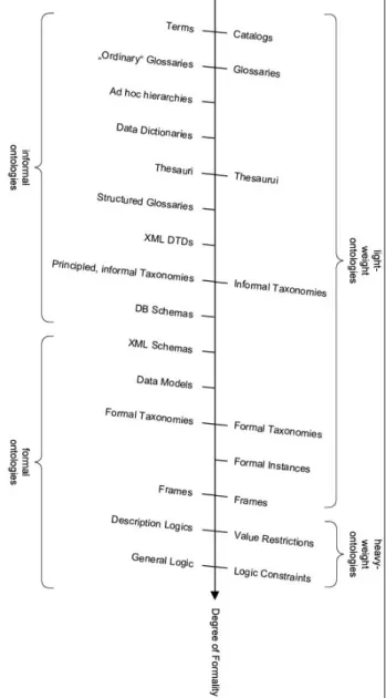
In 2001 lassila and McGuiness [10] provide a more detailed description and distinction between several types of ontologies shown and classified in the next picture:
Figure 6 – Ontology types based on the degree of formality
The types of presented ontologies are:
Catalogs – are collections of terms without any further description.
Glossaries – are catalogs that are enriched with descriptions for the terms.
Thesauri – contain additional relations between terms. Typically, those are relations such as “synonym of”, “broader term than” or “narrower term than”.
Informal taxonomies – arrange the terms in a hierarchy. An example is the concept hierarchies used by web shops.
Formal instances – are taxonomies that also explicitly define instances.
Frames – are used to define relations between concepts, e.g. that each food products is made from ingredients. Value restrictions – impose additional domain and range constraints on such frames, such as that only eatable substances can be used as ingredients for food products. Logic constraints – are constraints that go beyond domain and range definitions, e.g. stating that categories of objects are disjoint.
It exists another wide level of classification of ontologies: referring the figure nº 6 , we can say that the first four (from the left) are sometimes referred as “informal ontologies”, and the last five (near the bottom) are “formal ontologies”.
Another distinction that is several times used is “lightweight” and “heavyweight”, where “heavyweight” includes value restriction and logic constraints and “lightweight” includes all the other categories, like show in the figure at left. As depicted in the figure, Uschold and Grünninger [10] further refine the classification given by Lassila and McGuiness [10] by adding the following classifications:
Ad hoc hierarchies – are even weaker than informal taxonomies. The hierarchies do not even intend to create correct is-a relations, but only group things that roughly belong together.
Data dictionaries – define complex types of data based on simple ones e.g., a date being composed by a day, a month, a year.
Structured glossaries – contain further relations between terms, e.g. synonym and antonym relations.
XTML DTD’s – are meta-descriptions of XML documents. They define which elements in a XML file can exist and how they can be nested, showing the relations between all its elements. These nesting and relations provide informal, unnamed relations between nested elements.
Database schemas – describe tables in a database, their elements and their relations.
XML schemas – have the same purpose as XML DTD’s but are more expressive.
Data models – refer to models that go beyond database schemas, e.g., UML-based models, possibly with additional constraints.
There are some other criteria to classify the ontologies; regarding its contents, Van Heijst [10] enumerates four types of ontologies:
• Domain Ontologies - define concepts of one specific domain.
• Application Ontologies – define concepts from a domain that are required for one application. • Representation Ontologies – define the concepts
that are used to define ontologies, i.e. they define concepts such as term or relation. They can also be considered as meta-ontologies (Ontologies used to define ontologies).
Reusability
In “domain ontologies” and “generic ontologies” we registered a high level of reusability of the concepts and terms but not in “application ontologies”, because normally they refer to a very particular domain of knowledge.
A similar distinction is used by Uschold and Jasper [10] The authors distinguish three meta-type (or meta-levels) of ontologies:
L0 – Operational Data – defines knowledge about instances such as “Lisbon is a city”.
L1 – Ontologies – define the concepts and terms of a domain. Ontologies provide the vocabulary to define operational data.
L2 – Ontology representation languages provide means for defining L1 ontologies.
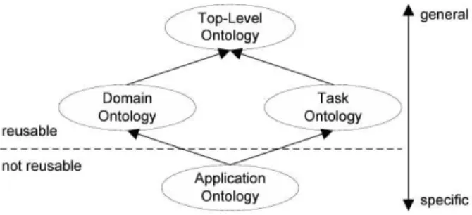
The classification proposed by Guarino [10] distinguish ontologies by their level of abstraction and their usage as shown in the next figure.
Some of the ontology types resemble those in the classification by Heijst [10] and other authors as referred above.
Top-level ontologies of upper-ontologies – are equivalent to “generic ontologies”. They contain general concepts that are useful across several domains, most often based on human perception of the world [10], proposed by Kiryakov and other authors.
Domain Ontologies – are equivalent to domain ontologies as are defined by Heijst and other authors[10].
Task Ontologies – define the activities of a task but without pointing a specific domain. For example scientific experiments contain hypotheses, measurements and evaluations, all of which can be defined agnostic to the actual domain of the experiment.
Application Ontologies – are equivalent to domain ontologies as defined by Heijst and other authors[10]. They identify the concepts defined in domain and task ontologies to define specific activities. This is done by stating which entities from the domain of that particular ontology plays which role in an activity defined in the task ontology.
The ontologies of the different levels are interconnected with specialization relationships. Thus, ontologies reuse definitions made by other ontologies on a higher level, therefore making them modular and comparable.
Figure 7 - Classification of ontologies based on their level of abstraction, following Guarino (1998, p. 7).
The main advantages of the use of a Ontology are: • Share common understanding of the structure of
the information among people or software agents
• To enable reuse of domain knowledge • To make domain assumptions explicit
• To separate domain knowledge from the operation knowledge
• To analyze domain knowledge
For the purposes for what we want use the ontology, we can consider that an Ontology is a formal explicit description of concepts in a domain of discourse.
The main elements of an Ontology are: • Classes, sometimes called concepts
• Slots, are the properties of each concept describing various features and attributes of the concept. Sometimes slots are also called roles or properties
• Facets , are restrictions on slots, or even properties of slots, or restrictions of slots An Ontology together with a set of individual instances of classes constitutes a knowledge base.
In reality, there is a fine line where the ontology ends, and the knowledge base begins.
In pratical terms, developing an Ontology includes: • Defining the classes of the Ontology
• Arranging the classes in a taxonomic (sub-class – superclass) hierarchy
• Defining slots and describing allowed values for theses slots
• Filing in the values for slots for instances We can then create a knowledge base by defining individual instances of each classes filling in specific slot value information and additional slot restrictions.
To design correctly an ontology we must respect the following rules. These rules may seem rather dogmatic, but they can help to make correct design decisions in most of the cases where ontologies can be applied:
1. There is no one correct way to model a domain of knowledge – there are always several alternatives. The best way to implement our ontology depends on the application that we have in hands, and all the extensions of it that was possible to us to anticipate.
3. Concepts in ontology should be very close to objects (physical or logic) and also close from the relationship that exist in the domain where we define the ontology.
4. Probably the most common is to define nouns (objects) or verbs (relationships) in sentences that describe your domain.
In a most detailed way, we can say that there are some steps that we must follow to define our ontology:
Step n. 1: Determine the domain and scope of our ontology.
To do this we must essentially to respond to the following questions:
• What is the domain that the ontology will cover ?
• For what we going to use the ontology ?
• For what types of questions the information on the ontology should provide answers ?
• Who will use and maintain the ontology ? Step n. 2: Consider reusing existing ontologies:
It most always worth considering what someone else has done and checking if we can refine and extend existing sources for our particular domain and task.
Reusing existing ontologies may be a requirement if our system needs to interact with other applications that have already committed to particular ontologies or controlled vocabularies.
Step n. 3: Enumerate important terms in the Ontology: It is useful it write down a list of all terms we would like either to make statements about or to explain to a user. Step n. 4: Define the classes and the class hierarchy: These are several possible approaches in developing a class hierarchy (Uschold and Gruminger 1996):
• Top-down development process:
o Starts with the definitions of the most general concepts in the domain and subsequent specialization of concepts. • Bottom-up development process:
o Starts with the definition of the most specific classes, the leaves of the hierarcly, with subsequent grouwing of these classes in more general concepts. • Combination development process:
This is really a combination of top-down and bottom-up approaches: we define the most salient concepts first and then generalize and specialize them appropriately.
None of these three methods is inherently better then any of the others. The approach to take depends strongly on the personal view of the domain and the situation in particular.
If a developer has a personal top-down view of the domain, then it may be easier to use the top-down approach.
However the combination approach is often the easiest way for many ontology developers, since the concepts “in the middle” tend to be the more descriptive concepts in the domain (Roch 1978).
Step n. 5: Define the properties of class-slots:
The classes done will not provide enough information to answer the competency questions.
Once we have defines some of the classes, we must describe the internal structure of concepts.
In general, there are several types of object properties that can become slots in an ontology:
If we take as example a Ontology about wines, we must considerer the following:
• “Intrinsic” properties (ex: flavor of a wine)
• “Extrinsic” properties (Name of the wine and area of production)
• “Parts” if the object is structures, these can be both physical and abstract “parts” (Indicated dishes to drink with)
• “Relationships to other individuals," these are relationships between individual members of the class and other items( maker of the wine, type of greap”
Note: All the subclasses of a class inherit the slot of a class.
Step n. 6: Define the facets of the slots:
Slots can have different facets describing the value type, allowed values, the number of values (cardinality), and other features of the value the slot can take.
Some normal common facets are:
Slot Cardinality: Defines how many values a slot can have some details:
• Some systems distinguish between single cardinality (Allowing at least one value) and multiple cardinality (allowing any number os values)
• Some systems allow the specification of a maximum and a minimum cardinality to describe the number of slots more that a slot must have at least N Values.
Slot value Type, they have some possible types that corresponds to the common variable data types:
• String
• Number (Float or integer) • Boolean (yes-no flag`s)
• Enumerated (list of specific allowed values) o Instance (instance-type slots allows
the definition of relationship between individual.
The classes to which a slot is attached or the classes which property a slot describes, are called the domain of the slot.
We can define the range of a slot as the allowed classes for slots of type instance.
Some systems allow restricting the range of a slot when the slot is attached to a particular class.
Step n. 7: Create instances:
The last step to create an ontology is creating individual instances of classes in the hierarchy. To accomplish this step we must do the following “sub-steps”:
1. Choosing a class
2. Creating as individual instance of that class 3. Filling the slot values
One of the objectives of this work is to build and define libraries of reusable knowledge components, (like RLO reusable learning objects in SCORM specification) and also Knowledge – based services than can be invoked over networks; to achieve this objective the most indicated structure to define and describe all the elements of a virtual laboratory as parts and components is an ontology, by the above reasons exposed.
Also we can say that an ontology permit to describe in a very detailed way the components / elements of the “virtual closet”, with all is details and features.
So formally we can say that an Ontology is the statement of a logical theory.
In a pragmatic way we can say that an Ontology defines the vocabulary with which queries and assertions are exchanged between systems that communicate in the v-labs network.
Ontological commitments constitutes agreements that should be used as shared vocabulary in a coherent and consistent way.
As conclusion of this introduction we can say: “an ontology is a particular system of categories accounting for a certain vision of the world. This system does not depend of a particular language. A shared ontology need only describe a vocabulary for talking about a domain, where as a knowledge base may include the knowledge needed to some a problem or answer arbitrary about a domain”.
DESIGN MODEL
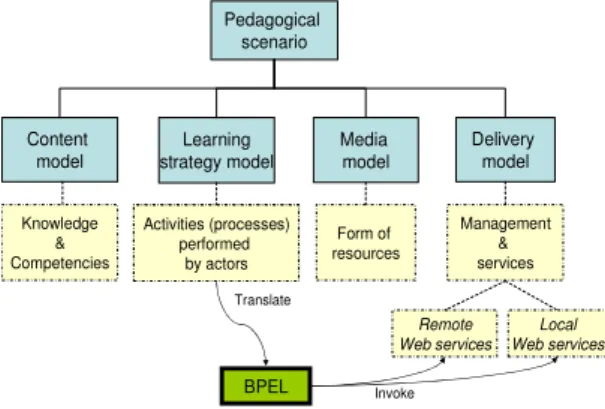
The design of a remote laboratory environment, unlike that of a classical distance-learning system, requires planning, actor access as well as an emphasis on the concept of real time to efficiently manage various resources, including dynamic learning objects and communication tools. MISA[22] is based on a design approach that respects the definitions of
four models used to describe a learning scenario: content, learning strategy, media and delivery [34]. Figure 8
illustrates this pedagogical model, how the components are linked, as well as the interactions amongst them. Web services will be used to link these components. A web service architecture will thus be defined to ensure the most important operations allow for the publication of a Web service, as well as the research and links within the service. These Web services will be built from either the Workflow mechanism through WSFL (Web Services Flow Language) [5] or BPEL (Business Process Execution Language) [6] which defines the specifications of a business process based on the Web service.
Figure 8 – Remote laboratory pedagogical model
The IMS-Learning Design specification (IMS-LD) was proposed by the IMS Consortium [25]. When the final version was published in February 2003, it was composed of three documents:
• IMS Learning Design Information Model: this document describes the data structure, the behavioral model for delivery and the conceptual model. • IMS Learning Design Information Binding: this
document provides further details concerning the elements which link data.
• IMS Learning Design Best Practice Guide: this document indicates how the specification must be implemented. It offers examples of courses with IMS-LD[22] specifications.
The specification of the conceptual model includes three implementation levels. Each one has a specific XML schema [25]:
• Level A: contains all of the basic elements: roles, activities, environments and structure of the methodology.
• Level B: builds on Level A; adds proprieties and conditions required for personalization and adaptability.
• Level C: adds the concept of Notification to Level B in order to fulfill collaboration and feedback requirements.
The objective for providing designers with an instructional meta-model based on these specifications is to facilate in describing learning scenarios. According to Koper [37], this IMS-LD model will make it possible to describe, in an inter-operable manner first, all of the process, content and services used in the framework of a
Pedagogical scenario
Content model
Learning strategy model
Media model
Delivery model
Knowledge & Competencies
Activities (processes) performed
by actors
Form of resources
Management & services
Remote Web services
Local Web services
Invoke BPEL
Translate Activities (processes)
course. Second, it will also ensure assistance to personalize learning activities and reuse course components and multi-role instructional designs.
Our solution to the problem / our ontology:
To implement and build the ontology we go use the software “Protégé” that is a tool specially developed to build ontologies.
Protegé is a software that allows easily to build ontologies respecting all the rules that we define in our system.
In Protegé we define what will be the classes and also we can define all the relations between them.
In our particular case the “root” or Master-class of our ontology is “LABORATORY”:
Figure 7 – EuronetLab Ontology definition
From there we define three main classes:
• Experiment • Real Component • Virtual Component
Essentially the ontologies used in this field of knowledge using semantic web technologies. We can define ,according to the W3C, "The Semantic Web provides a common framework that allows data to be shared and reused across application, enterprise, and community boundaries." Tim Berners-Lee defines the Semantic Web as "a web of data that can be processed directly and indirectly by machines."
All the laboratories are composed by experiments, that we can define as:
“An experiment is the smallest enclosed unit of an online laboratory. It provides also the execution of virtual or real experiments to observe the behavior and output of a system. An online laboratory consists of one or more experiments in different fields of science and engineering”. Ref. [1]. Also normally, associated to an online laboratory, there must be other learning resources like a laboratory tutorial and lecture notes to provide the theoretical background necessary to carry out an experiment. Therefore, it is necessary to provide a variety of additional documents and references. Ref. [1]. So is very important to have as support of all this system a CMS or a e-learning platform that interconnect the build ontology with the v-labs proposed in the “virtual closet”. The CMS , LMS or a e-learning platform allows the existence and organization of all this pedagogical and technical pedagogical contents and supports.
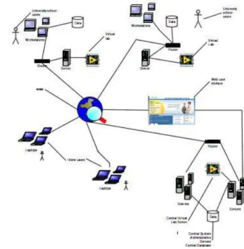
The proposed network as the following block-diagram:
In this network we have three main actors: • Teachers
• Students and Researchers
• Administrative staff
A login, forms and database must be created using ASP or PHP that allows students to:
• Schedule an experiment in a certain lab; • Verify available labs and in which universities
or institutes are located;
• Verify the experiments they have done, their grade and comments from their teachers; • Read or review pedagogical contents that
support the different experiments. The teachers should be able to:
• Send pedagogical contents; • Review contents and materials; • Evaluate the students’ Works;
• Communicate with the students using email, chat, video-conference in order to give orientations and clarify subjects.
The administrative staff should support all the non-technical issues and administrative issues derived from the communication between universities, institutions, teachers, researchers and students.
This is the way that we think that this V-labs network , the “Euronet – Lab” should work. Ref. [5]. Ref [6].
SYSTEM SECURITY
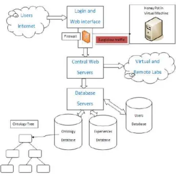
One of the most important components of an open system like Lab@DER and EURONET-LAB is the security component, and in this one we must use a “Honey Pot” that diverts the malicious users to this virtual machine like shows the next picture:
Figure 9 – Remote laboratories environment and security software system
The “Login and Web Interface” block as the following functions:
• Guarantee to the users a secure and efficient way of making login in the system
• Validate the login action by the users an “pass the section” to the block “Central Web Servers” The block “Central Web Servers” as the following
functions:
• Run the schedule system of labs/experiences • Transmit the data and make the connections with
the VPC servers on the VPN
• Associate the scheduled experience and time to the real system in the cloud owner the internet, using a mapping IP addressing system, on a cloud network
• Receive and direct the correct
experiment/laboratory to the connections of the users received via “login and web” interface
The block “Database Servers” as the function of connect the registered requests with the three Database on the Cloud, the Ontology Database, the Experiences/Labs Database and the users Database.
In a technical level what should be done is essentialy a correct instalation and configuration of a Firewall System and an IDS – Intrusion Detection System.
Is necessary also build and configure a DMZ (Demilitarized Zone), where must be placed the servers that should be accessed from outside the network, the Webserver and FTP Server.
false DMZ, in which must be installed a “Honey Pot” and the image (false image) of a virtual network, where hackers should be “trapped” when try to attack the network.
Figure 10 – Security and firewall system
FUTURE DEVELOPMENTS
The following action to take in this project is to build a prototype system that interconnects the build ontology with the v-labs network and the LMS databases that support the administrative parts of the system as shown in the fig #10.
Figure 11 – EuronetLab database and VPN structure
ACKNOWLEDGMENT
This work was supported in part by IPS – Instituto Politécnico de Setúbal – Escola Superior de Tecnologia de Setúbal and IEEE Working Group: Networked Smart Learning for Online Laboratories (EDU/SC/NSLOL), New IEEE Standard Project Number P1876.
REFERENCES
[1] Abul K.M. Azad et al., Internet Accessible Remote Laboratories: Scalable E-Learning Tools for Engineering and Science Disciplines, Engineering Science Reference (an imprint of IGI Global) 701 E. Chocolate Avenue Hershey PA 17033 Tel: 8845 Fax: 717-533-8661 E-mail: cust@igi-global.com Web site:
http://www.igi-global.com.
[2] Gruber, T.R., 1993a. Toward Principles for the Design of Ontologies Used for Knowledge Sharing N. Guarino & R. Poli, eds. International Journal of Human-Computer Studies, 43(5-6), pp.907-928. Available at: http://linkinghub.elsevier.com/retrieve/doi/10.1006/ijhc.1995.1081.
[3] Gruber, T.R., 1993b. Toward Principles for the Design of Ontologies Used for Knowledge Sharing N. Guarino & R. Poli, eds. International Journal of Human-Computer Studies, 43(5-6), pp.907-928. Available at:
http://linkinghub.elsevier.com/retrieve/doi/10.1006/ijhc.1995.1081.
[4] Noy, N.F. & Mcguinness, D.L., 2000. Ontology Development 101: A Guide to Creating Your First Ontology. Development, 32(1), pp.1-25. Available at:
http://citeseerx.ist.psu.edu/viewdoc/download?doi=10.1.1.136.5085&a mp;rep=rep1&type=pdf.
[5] Cordeiro, R., Fonseca, J. M., & Donellan, A. (n.d.). A Cloud Based Laboratory Environment.
[6] Cordeiro R., Passos, H., ed. Virtual Labs in the E-Learning Context as Tools of Collaboration Work. EDULEARN 09. 2009: Barcelona.
[7] FlecharM (2010) HypeCycle for Application
Development.http://www.gartner.com/DisplayDocument?id=1412014,a ccessed April12th,2011.
[8] AmsdenJ(2001) Levels Of Integration-Fiveways you can integrate with the EclipsePlatform. http://www.eclipse.org/articles/Article-Levels-Of-Integration/levels-of-integration.html,accessed April 12th,2011.
[9] Nilsson EG, NordhagenEK,OftedalG(1990) Aspects of systems integration.In:ISCI’90:Proceedingsof the first international conference on systems integrationon Systems integration’90, IEEEPress,pp 434– 443
[10] Paulheim, Heiki, Ontology-based Application Integration, e-books: www.e-books.com, accessed August 17 th , on 2012.
[11] Scheifler RW,GettysJ (1986) The X WindowSystem.ACM Transactions on Graphics5(2):79–109
[12] LinthicumDS(1999) Enterprise Application Integration. Addison Wesley
[13] BenatallahB,NezhadHRM(2007) Service Oriented Architecture: Overviewand Directions. In: B¨orgerE,CisterninoA(eds) Advances in Software Engineering, Springer,LNCS,vol5316,pp 116–130
[14] Rebstock M,Fengel J,Paulheim H(2008) Ontologies-based Business Integration. Springer
[15] Daniel F,Matera M(2008) Mashing Up Context-Aware Web Applications: AComponent-Based Development Approach.In: WISE’08: Proceedings of the 9th international conferenceon Web Information Systems Engineering,Springer,LNCS,vol5175,pp250–263
[16] WestermannU,Jain R(2007) Toward a Common Event Model for Multimedia Applications.IEEE MultiMedia14(1): 19–29
[18] Uschold M,Gruninger M (1996) Ontologies:Principles, Methods and Applications.Knowledge Engineering Review11:93–136
[19] Gruber T R (1995) Toward Principles for the Design of Ontologies Used for Knowledge Sharing. International Journal Human-Computer Studies 43(5-6):907–928
[20] Guarino N,Giaretta P (1995) Ontologies and KnowledgeBases: Towards a Terminological Clarification. In:MarsNJI(ed) Towards Very Large Knowledge Bases:Knowledge Building and Knowledge Sharing,IOSPress,Amsterdam, pp25–32
[21] Guarino N,Welty CA(2009)An Overview of Onto Clean.In:(StaabandStuder,2009),chap10,pp 201–220
[22] Salliah-Hassane H. Bochaib F. ,2004,Pedagogical Engineering Fundamentals to Build Robust Software Comnponents for Online Laboratories.
[23] Wayne Hodgins. Standards for Information Technology-Education and Training Systems- Learning Object and Metadata. IEEE Learning Technology Standards Committee, December 2002. Available from web: <URL: http://ltsc.ieee.org/wg12/index.html>
[24] IMS Global Learning Consortium, Inc. IMS Learning Design Best Practice and Implementation Guide, October 2002. Available from web: <URL: http://www.imsglobal.org/learningdesign/>
[25] IMS-LD, IMS Learning Design, http://www.imsglobal.org/learningdesign/
[26] Masmoudi, A., Paquette, G., & Champagne, R. (2006, 1-3 juin). Implémentation à l'aide de BPEL de trois processus d'agrégation de composants, dirigée par les modèles. Article accepté à la conférence INFORSID'06, Hammamet-Tunisie.
[27] Masmoudi, A., Paquette, G., & Champagne, R. (2006, 31 mai). Recherche des composants logiciels référencés par un modèle ontologique. Article accepté à l’atelier OCM-SI de la conférence INFORSID'06, Hammamet-Tunisie.
[28] Masmoudi, A., Paquette, G., & Champagne, R. (2005). Agrégation de Composant logiciel Dirigée par les Métadonnées. Papier présenté à l’atelier OCM de la conférence INFORSID, Grenoble-France, mai 2005.
[29] Saliah-Hassane, H., I. De La Teja, M. Saad,"Outils, environnement et méthodologie pour l'encadrement et la formation d'équipes
multidisciplinaires en génie travaillant en réseau par le Web", dans Prospectives Francophones, B. Leduc (ed.) "Former des Ingénieurs par l'université virtuelle", Presses Universitaires de Bruxelles, a.s.b.l., 2001, pp. 125-140.
http://www.licef.teluq.uquebec.ca/sh/HTML/JITVII_Saliah.pdf
[30] Cordeiro R., Fonseca J., Donnellan A., (2012). Ontology: A Support Structure for a V-Labs Network: Euronet-Lab. International Journal of Online Engineering (iJOE), Vol 8 (2012)
[31] Saliah H. H., I. De la Teja, O. Dioume, C. Kedowide, G. Paquette, M. Saad, L. Villardier,, (2012). Online Laboratory Brokerage System for Education and Research, International Conference on Engineering Education. July 21–25, 2003, Valencia, Spain.
[32] Saliah, H. H., Loizeau, C., Dumont-Burnett, P., "Design of a Web-Based Virtual Laboratory Instrument Measurement Interface", in W. Aung, P. Hicks, L. Scavarda, V. Roubicek, C. Wei (eds.) "Engineering Education and Research 2001, A Chronicle of Worldwide Innovations"; BEGELL HOUSE PUBLISHING, 2002, Chap. 13, pp.127-134.
[33] Saliah, H. H., Saad,M., Hassan, H., De La Teja, I., "Virtually and remotely accessing and controlling laboratory real devices: A new trend in teaching and learning in engineering", "Proceedings of the International Conference on Information Technology Based
Higher Education and Training ITHET 2000"; Istanbul, July 3-5, 2000, pp. 107-114.
[34] Wayne Hodgins. Standards for Information Technology-Education and Training Systems- Learning Object and Metadata. IEEE Learning Technology Standards Committee, December 2002. Available from web: <URL: http://ltsc.ieee.org/wg12/index.html>
[35] Ontology-Mediated Integration of Intranet Web Services, October 2003. IEEE Computer Society
[36] Saliah, H. H., Masmoudi A., Paquette G.,., "Développement d’ un scenario de laboratoire en ligne par une aggregation de composants logiciéles basée sur les ontologies".
[37] Koper, R. (2004). IMS Learning Design: What it is & Update on Current Activities Heerlen, Oct. 21, 2004, Educational Technology Expertise Center, Open University or the Netherlands, Unfold & Surf Six Joint Meeting
AUTHORS
Hamadou Saliah is Senior IEEE member, Professor and Researcher in TELUQ Université du Québec, LICEF Research Center.
Email: saliah@teluq.ca
Raúl Cordeiro Correia is with the Instituto Politécnico de Setúbal – Escola Superior de Tecnologia de Setubal, Largo Defensores da Republica nº 1, 2910-470 Setúbal, PORTUGAL
e-mail: raul.correia@estsetubal.ips.pt
José Manuel Fonseca is Professor in the Electrical Engineering Department of the Universidade Nova de Lisboa, Campus da FCT/UNL, 2829-516 Caparica, Portugal
![Figure 1 – Pedagogical model [22]](https://thumb-eu.123doks.com/thumbv2/123dok_br/18777424.406553/2.892.92.435.114.333/figure-pedagogical-model.webp)
![Figure 2 – Classification of levels [10]](https://thumb-eu.123doks.com/thumbv2/123dok_br/18777424.406553/3.892.89.436.209.939/figure-classification-of-levels.webp)