Paper Title:
Generic Framework for Video Analysis
Authors:
Luís Filipe Tavares INESC Porto [email protected] Luís Teixeira
INESC Porto, Universidade Católica Portuguesa [email protected]
Luís Corte-Real
INESC Porto, Faculdade de Engenharia da Universidade do Porto [email protected]
In:
Proceedings of RECPAD’2002 - 12th Portuguese Conference on Pattern Recognition June 27th- 28th, 2002
Generic Framework for Video Analysis
Luís Filipe Tavares
1, Luís Teixeira
1,2, Luís Corte-Real
1,31
Instituto de Engenharia de Sistemas e Computadores do Porto
Praça da República, 93 r/c, 4050-497 Porto, PORTUGAL
email: lft, lmt,
[email protected]
2
Universidade Católica Portuguesa
R. Diogo Botelho, 1327, 4169-005 Porto, PORTUGAL
email:
[email protected]
3
Faculdade de Engenharia da Universidade do Porto
R. Dr. Roberto Frias, 4200-465 Porto, PORTUGAL
email :
[email protected]
Abstract - In this paper we propose a framework for development of video analysis and description systems, in an easy and interactive way. Due to the architecture design the developed software can run on different operating systems and on distributed environments.
I. INTRODUCTION
Due to the noticeably fast development in the digital world, we now have available a wide range of video
analysis tools to satisfy the needs that arise with such new
technologies. New different approaches are emerging everyday, each one with its own purposes, requirements and data structures. This diversity comes up like a problem in the integration of such video tools. Providing a way to simplify the integration and thus the reusability of the video tools in different contexts is the main goal of our work. The first tools to be integrated had been developed in internal research projects but the environment allows the integration of external toolkits such as Open Computer Vision Library or the Java Imaging Lib [1,2]. The proposed framework will satisfy the following constrains:
• to provide a comfortable, user-friendly graphical environment,
• seamless integration of video analysing tools developed by INESC or externals;
• expansibility by allowing the integration of new algorithms in the application;
• portability between Unix and Windows;
• capability to perform in a distributed environment;
• support for reusable super-structures;
• fast development of prototypes.
In section II, we make a short description of some issues that lead us to adopt the proposed solution. Main
implementation and structure aspects are presented, justifying the choices we have adopted. Then we make a brief description of the application. After referring a few architecture details, section III introduces the Graphical User Interface and presents its main components. The section ends with a simple example of a processing system built with this application. Section IV first refers to technical details about the overall functioning of the application and the interaction between the different modules. Here, we take a closer look on key aspects like data flow, control and synchronization scheme. We then describe some of the features available in the current version. The section ends evaluating the suggestion of two user profiles for this application. In section V we make some final remarks.
II. SYSTEM IMPLEMENTATIONS ISSUES
One of the main problems we dealt with in the design of our application was the diversity of data video formats and structures handled by all the video tools. For instance, we can be working with image data and image statistics using different video tools. Performance is also important as most of video processing tools impose hard requirements on system resources.
Another requirement was the system portability (including graphical environment). Java was chosen for the GUI implementation due to its high level architecture and portability inherent characteristics. Most of the algorithms were already available in C language due to performance. We could include C routines as native code inside Java, using JNI – Java Native Interface. This solution was avoided as it would slow down the execution and it would not support algorithms implemented in certain languages. We decided to use standalone-processing engines, one for each algorithm. Each individual video tool is encapsulated with a module that allows it to exchange information via
socket with the system environment. A communications protocol was defined (section III).
III. SYSTEM ARCHITECTURE A. Communication Architecture
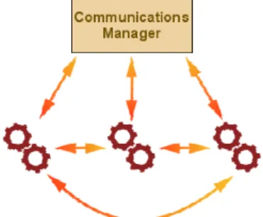
The communication is made via UDP sockets, following a “One Server – Multiple Clients” philosophy (see Fig.1). The server module, “Communications Manager”, is implemented in Java. The server block allocates a thread and a unique socket address per video tool (engine). The sockets are the channels that the processing engines (the C routines that actually do all the processing) use to communicate with the server (Java) side.
During the initialisation process, each engine also creates its own socket. This allows the Communications Manager to instruct any pair of engines to establish a direct message exchange between them.
Each engine has its own associated inputs and outputs, which are identified within the algorithm by their ID numbers. Thus it is possible to instruct one process to send the data available in a specific output (an array of bytes containing image data, for instance) to a specified input in another process. So data flows directly from one algorithm to the other.
The synchronization also relies on the exchange of “event
messages” between both sides of the application (Section
IV).
The adopted communication scheme, besides allowing the interaction between the Java and the C sides, also represents a solution for the other problem we mentioned in Section III: the data diversity issue. In fact, sockets support all types of digital data (image data, image statistics, etc), allowing the integration level we seek with this work.
The use of network resources to support the Inter-Process Communication has yet another advantage. In fact, a simple change from UDP to TCP sockets would make it very simple to spread the engines over several machines. This satisfies another proposed requirement: the ability to run in a distributed environment.
B. Graphical User Interface
Processing engines are represented in the GUI by components we call Processing Blocks, whose inputs and outputs are represented by nodes. Nodes are related to their respective Processing Blocks by an ownership association.
To make a block diagram (Fig.2), the user inserts the desired blocks and associates them by connecting their outputs to compatible inputs of other Processing Blocks establishing therefore a “Parent-Child” relationship. These associations represent not only the data flow between the correspondent inputs and outputs, but also the event notifications that need to be given to the server. A Producer-Consumer relationship is established between two related nodes regarding the notification scheme. There are two special types of Processing Blocks:
• File;
• Test point.
The first one represents a connection to a source, like a file containing image data. The source could also be some kind of capture device. A “Test point” provides the user with the possibility of monitoring the sequence at any point of the processing system.
Fig. 1 - Communications Architecture
Fig.2 – Simple Processing System
The first block in the processing chain in Fig.2 represents the input video file or a stream outputted by a capture device. Looking at the diagram, one can see that the sequence is submitted three parallel processing stages. From the top to the bottom, one can see a Pass-Through
Codec, a chain composed by an Optical Flow detector
(performed by the Lucas-Kanade algorithm) and it’s correspondent arrow image generator and another chain composed by a binarization block followed by a contour detector.
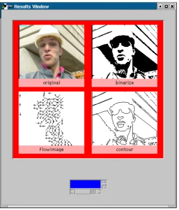
Fig.3 presents the results obtained with the system of Fig.2. In the left upper corner one can see the last frame of the original sequence. The results of the processing
blocks, namely the binarization block, the optical flow detection block and the contour detector block, are also presented. The layout of the results window is defined in the editing mode.
The processing chain shown in Fig.2 can also be kept as a reusable block (super-structure) for future use. As expansibility was one of our requirements, we have provided a way to add new algorithms to the application (Section IV)
IV. APPLICATION OVERVIEW
The application has two separate modes of operation: the
Editing Mode and the Execution Mode. In the first mode
the user creates a system, adding blocks to the workspace and associating them. In the Execution Mode, the application executes the operations defined in the editing mode. The synchronization of all the processes is
Event-Oriented, because of variable delay in different processing
task. The control is centralized in the Java side of the application, which keeps trace of the current state of every node in the system.
The synchronization of all the modules relies on a notification scheme, where each component in the system notifies its directly associated components of every state change.
A. Implemented Features
The current version has already a wide variety of tools that one can use to perform some interesting operations.
We will now enumerate some of the image and video analysis algorithms that we have included:
• Global features extraction
• Histogram expansion.
• Image combination, rotation, scaling.
• Filters like Low-Pass, High-Pass, Median Filter,
Gaussian, etc. • Peak detection.
• Binarization and multilevel threshold.
• Region growing.
• Edge detection.
• Template matching.
• Object thinning.
• Hough transform.
• Fast Fourier Transform.
• Subtitle and logo extraction.
B. Expansibility
In the first approach to this goal, the integration of a new tool was made adding a line to an index file. The line contained simple information about the algorithm to be added:
• Name of the GUI component.
• Location of the executable.
• Number of inputs and outputs.
• The type of the different inputs and outputs (image, regular text, statistics…).
Fig. 3 – Results Window
When we began testing other algorithms in the framework, we were confronted with the need to provide a more detailed description of the new tool, not only to provide validation of the whole processing system, but also to allow a complete customisation of the behaviour of each tool. For instance, we must include a description of the customisable parameters for the new tool, their data type and the allowed range of variation for each parameter. To avoid this level of complexity, we have decided to use one file for each algorithm.
The user integrates a new tool in the framework by accessing a menu “Add new Tool”, selecting the previous hand generated description file and selecting the tool group.
Regarding the engines code, we need to add a code segment before inputs processing, another to control loop processing and the last one after the processing is complete. The first segment of code forces the engine to wait for a “load inputs” command (sent by the manager in the Java side). After the reception of this command, the engine retrieves the data from the appropriate source (file or socket) and sends an “inputs loaded” notification to the manager. The second segment of code to be included simply forces the engine to wait for a “begin processing” command. The third code segment notifies the manager of the completion of the task, which means that new data is available at the outputs of the engine.
We also need to include a function to parse the command line arguments, like the input and output filenames and the algorithm’s specific set of parameters (stored in a file with the extension “*.par”). This simple method of integration provides our application with the desired expansibility.
C. Modularity
The desired modularity features are still in development. In the final version of the described framework, the application will provide two extra features:
• Creation of new modules from user-defined systems. These modules will act like subsystems in a larger and more complex project. Within this project, each module is seen like a black-box for which we can configure a pre-determined set of parameters.
• Use the modules referred in the last paragraph as stand-alone applications, meant to accomplish a very specific task.
Thus we expect to simplify the design of complex systems, by decreasing both implementation and graphical complexity associated with a system containing a large number of Processing Blocks. By grouping a subset of functions that cooperate to the same task, we can see this subsystem from a higher perspective, disregarding details that would distract us from our higher-level objectives. At the same time, the capability of creating subsystems greatly simplifies the process of testing and debugging, by proving the user with the possibility of testing the functionality of the newly created groups.
The capability of creating stand-alone applications with systems developed in this framework is meant to allow the development of prototypes suited for a specific task, like, for instance, motion detection in a surveillance system.
D. User profiles
We have consider two profiles of users for this application:
1. The user who is experienced with video processing techniques, and needs a simple tool to develop complex systems. This user may employ the available algorithms to easily build a system capable of performing complex high-level operations, without having to develop a whole software package to accomplish his goals.
2. The user who needs an application to accomplish a specific task, without having to worry about inner details. Because this user only needs to have control over a few of the parameters involved in the processing system, the application provides the interface to control only the parameters the user is interested in.
V. CONCLUSIONS
We have presented a framework for the development of video processing and analysis systems, in an easy and interactive way. Regarding the performance of the created application, we can say that the graphical environment has good responsiveness and interaction with the user. Some of the interesting features of this application are:
• Portability - The application is portable or OS independent, due to the fact that none of the C routines deals with the graphics system. This way, we can have it running in several Operating Systems, as long as we recompile the source code in the correct environment. The Java modules are, of course, system-independent.
• Modularity - The application is modular, meaning that we can build blocks to be reused latter.
• Expansibility - The application is expansible, since new algorithms can easily be added to extend functionalities.
The proposed framework was designed with the following applications in mind:
• Content Video Description (useful for intelligent coding and content based video retrieval).
• Fast Application Development.
• Information Description (by the moment, this application is a proprietary system. In the future we plan to include support for XML, to be used in MPEG7).
• Academic usage, offering the possibility of teaching video analysis in an interactive way.
VI. ACKNOWLEDGEMENTS
This work was supported by the project CORAL - COntent-aware Resource ALlocation for digital TV service (POSI/CPS/34445/99).
REFERENCES
[1] Open Computer Vision Library http://support.intel.com/support/performancetools/libraries/ipl/index. htm
[2] Java Advanced Imaging API Specification, version 1.1, August 7, 2001