Universidade de Aveiro Departamento de
2008 Electr´onica, Telecomunica¸c˜oes e Inform´atica
Andreia
ESQUEMAS DE DIVERSIDADE COOPERATIVA
Universidade de Aveiro Departamento de
2008 Electr´onica, Telecomunica¸c˜oes e Inform´atica
Andreia
Esquemas de diversidade cooperativa para
Mo¸
co
sistemas sem fios
Cooperative diversity schemes for wireless
communication systems
Universidade de Aveiro Departamento de
2008 Electr´onica, Telecomunica¸c˜oes e Inform´atica
Andreia
Esquemas de diversidade cooperativa para
Mo¸
co
sistemas sem fios
Cooperative diversity schemes for wireless
communication systems
Disserta¸c˜ao apresentada `a Universidade de Aveiro para cumprimento dos requesi-tos necess´arios `a obten¸c˜ao do grau de Mestre em Engenharia Electr´onica e Tele-comunica¸c˜oes, realizada sob a orienta¸c˜ao cient´ıfica do Prof. Dr. Ad˜ao Silva, professor auxiliar convidado do Departamento de Electr´onica, Telecomunica¸c˜oes e Inform´atica da Universidade de Aveiro e Prof. Dr. At´ılio Gameiro, professor associado do Departamento de Electr´onica, Telecomunica¸c˜oes e Inform´atica da Universidade de Aveiro.
Apoio financeiro do projecto europeu CODIV (FP7-ICT-2007-215477).aaaa
o j´
uri / the jury
presidente / president
Prof. Dr. Jos´e Rodrigues Ferreira da RochaProfessor Catedr´atico da Universidade de Aveiro
vogais / examiners committee
Prof. Dr. At´ılio Manuel da Silva Gameiro (Co-orientador)Professor Associado do Departamento de Electr´onica, Telecomunica¸c˜oes e Inform´atica da Universidade de Aveiro
Prof. Dr. Paulo Jorge Coelho Marques
Professor Adjunto do Departamento de Engenharia Electrot´ecnica da Escola Superior de Tecnologia do Instituto Polit´ecnico de Castelo Branco
Prof. Dr. Ad˜ao Paulo Soares Silva (Orientador)
Professor auxiliar Convidado do Departamento de Electr´onica, Telecomunica¸c˜oes e In-form´atica da Universidade de Aveiro
agradecimentos /
acknowledgements
Ao Professor Ad˜ao Silva, por estar sempre dispon´ıvel para esclarecer as d´uvidas existentes e partilhar os seus conhecimentos. Revelou-se importante o esp´ırito cr´ıtico demonstrado pela mesmo na procura de mais e melhores solu¸c˜oes para os problemas encontrados.
Ao Professor At´ılio Gameiro pela disponibilidade demonstrada em partilhar os seus conhecimentos e fornecer informa¸c˜ao importante para o desenvolvimento desta disserta¸c˜ao.
Ao Professor Rui Aguiar por me ter chamado `a raz˜ao em v´arias ocasi˜oes cr´ıticas, desencorajando-me assim de enveredar por caminhos tortuosos. . .
Ao Instituto de Telecomunica¸c˜oes de Aveiro e seus colaboradores por me terem oferecido todas as condi¸c˜oes e apoio necess´arios para o desenvolvimento desta disserta¸c˜ao.
`
A minha fam´ılia por todo o apoio, paciˆencia e motiva¸c˜ao que me deram durante o desenvolvimento da disserta¸c˜ao.
palavras-chave
MIMO virtual, Sistemas com Relay, Diversidade cooperativa, Amplify-and-forward, Decode-and-Forward, Decode-and-Forward selectivo, Diversidade espacial, Propaga¸c˜ao multipercurso, Modula¸c˜ao multiportadora, OFDMA.resumo
A presente disserta¸c˜ao insere-se na ´area das comunica¸c˜oes sem fios, ou mais es-pecificamente na tem´atica da diversidade cooperativa.Neste trabalho ´e feito o estudo, implementa¸c˜ao e avalia¸c˜ao do desempenho de esquemas de diversidade cooperativa de baixa complexidade para sistemas de co-munica¸c˜ao m´ovel. Estes esquemas s˜ao mapeados em modelos de simula¸c˜ao basea-dos em OFDMA e s˜ao completamente simulados em CoCentric System Studio. Os resultados obtidos com os modelos desenvolvidos mostram que os esquemas de diversidade cooperativa atenuam os efeitos do desvanecimento induzido pela propaga¸c˜ao multipercurso, aumentando desta forma a capacidade e cobertura dos sistemas wireless. Os ganhos s˜ao particularmente altos quando as perdas de per-curso s˜ao consider´aveis, como ´e o caso das zonas urbanas densas.
keywords
Virtual MIMO, Relay system, Cooperative diversity, Amplify-and-forward, Decode-and-Forward, Selective decode-Decode-and-Forward, Space diversity, Multipath propaga-tion, Multicarrier modulapropaga-tion, OFDMA.abstract
This dissertation is inserted into the wireless communication, or more specifically, into the cooperative diversity field.within this thesis, the performance of low-complexity cooperative diversity schemes projected for mobile communication systems are studied, implemented and evalu-ated. These schemes are mapped into simulation models based on OFDMA and are fully simulated in the CoCentric System Studio environment. The obtained results show that the proposed cooperative schemes for the uplink communication mitigate fading induced by multipath propagation, thereby increasing the capacity and coverage of wireless systems. Cooperation gains are particularly high when multipath losses are considerable, as is the case for dense urban regions.
CONTENTS iii
Contents
Contents v
Acronyms and Abbreviations viii
List of Figures ix
List of Tables xi
1 INTRODUCTION 1
1.1 Introduction to Broadband Wireless . . . 1
1.1.1 Overview of 2G cellular systems . . . 2
1.1.2 Review of current wireless data standards . . . 2
1.1.3 Overview of 3G cellular systems . . . 4
1.1.4 Overview of LTE as a possible 4G . . . 5
1.2 Motivation and Objective . . . 9
1.2.1 Future demands high bit rates . . . 9
1.2.2 Cooperative Diversity History . . . 9
1.2.3 Preliminaries of Relaying . . . 10
1.2.4 Half-duplex versus Full-duplex Relaying . . . 12
1.2.5 Relay Protocols . . . 12
1.2.6 Scope of this Dissertation . . . 13
1.3 Organization . . . 14
2 THE COMMUNICATIONS CHANNEL 15 2.1 Statistical Models . . . 15
2.2 Median Path Loss . . . 17
2.3 Shadowing . . . 18
2.4 Fading . . . 18
2.4.1 Statistical Distributions for fast fading . . . 19
2.4.2 Delay Spread, Coherence bandwidth and Frequency Selectivity . . . 21
2.4.3 Doppler Spread, Coherence Time and Time Selectivity . . . 22
2.5 Channel Models proposed by HIPERLAN/2 . . . 24
3 MULTIANTENNA TECHNIQUES 27 3.1 Preliminaries . . . 27
3.1.1 Diversity Gain . . . 27
3.1.2 Ergodic and Outage Capacities as figures of merit . . . 28
3.1.3 Array Gain . . . 29
3.1.4 MIMO System Model . . . 29
3.2.1 Channel Unknown to the transmitter . . . 31
3.2.2 Channel Known to the transmitter . . . 31
3.2.3 Deterministic Channels . . . 31
3.3 Multiple antenna schemes . . . 32
3.3.1 Receive diversity . . . 34
3.3.2 Transmit diversity . . . 36
3.3.3 Spatial Multiplexing . . . 36
4 MULTICARRIER SYSTEMS 39 4.1 Orthogonal Frequency Division Multiplexing . . . 39
4.1.1 Advantages for mobile systems communications . . . 44
4.1.2 Turning multipath into an advantage . . . 45
4.2 Orthogonal Frequency Division Multiple Access . . . 45
4.2.1 Multiple access strategies for OFDM . . . 45
4.2.2 Subchannel allocation . . . 46
4.2.3 OFDMA implementation issues . . . 48
4.3 Overview of the physical layer of WiMAX . . . 49
4.3.1 OFDM parameters in fixed and mobile WiMAX . . . 50
4.3.2 Frame and slot structure . . . 52
4.3.3 Modulation and adaptive coding in WiMAX . . . 52
4.3.4 Advanced Features . . . 53
5 RELAY-ASSISTED COOPERATIVE SCHEMES 55 5.1 Introduction . . . 55
5.2 World Wide Initiatives . . . 57
5.2.1 IEEE 802.16j Standard Main Characteristics . . . 57
5.2.2 CODIV cooperation scenarios . . . 58
5.2.3 CODIV and 802.16j main differences and similarities . . . 63
5.3 Proposed Relay-Assisted Cooperative Schemes . . . 63
5.3.1 System Model . . . 63
5.3.2 Non-Cooperative MISO system . . . 64
5.3.3 Amplify and Forward . . . 65
5.3.4 Suboptimum Amplify and Forward . . . 66
5.3.5 Selective Decode and Forward . . . 67
5.4 Numerical Results . . . 69
5.4.1 Outage Capacity . . . 69
5.4.2 Bit Error Rate . . . 71
6 CONCLUSIONS 79 6.1 Achieved Results . . . 79
6.2 Extensions and continuing work . . . 80
Contributions and Future Application 83 A Matlab code for plotting CDF’s of SISO/SIMO systems 85 B Cocentric System Studio Environment 87 B.1 Cocentric System Studio . . . 87
B.2 Overview . . . 87
CONTENTS v
C Power Delay Profiles of HIPERLAN/2 models 91
C.1 Channel Model A . . . 91 C.2 Channel Model E . . . 92
Acronyms and Abbreviations
3G Third Generation Networks3GPP 3rd Generation Partnership Project 4G Fourth Generation Networks
ACK Acknowledgement
AF Amplify-and-Forward
AMC Adaptive Modulation and Coding BLAST Bell-Labs Layered Space-Time Bps Byte per second
BPSK Binary Phase Shift Keying
BS Base Station
CDF Cumulative Density Function CDMA Code Division Multiple Access
CODIV Enhanced Wireless Communication Systems Employing COoperative DIVersity CSI Channel State Information
DOA Direction of Arrival
DF Decode-and-Forward
EDGE Enhanced Data Rates for GSM Evolution EF Equalize-and-Forward
ETSI European Telecommunications Standards Institute FDD Frequency Division Duplexing
FDMA Frequency Division Multiple Access FEC Forward Error Correction
GI Guard Interval
GPRS General Packet Radio Service
GSM Global System for Mobile telecommunication IEEE Institute of Electrical and Electronics Engineers iid Independent and Identically Distributed
ITU International Telecommunication Union IP Internet Protocol
kbps kilobit per second LAN Local Area Network LDPC Low Density Parity Check LOS Line of Sight
ACRONYMS AND ABBREVIATIONS vii
MAC Media Access Control MAN Metropolitan Area Network
MC-CDMA Multiple Carrier - Code Division Multiple Access Mbps Megabit per seconde
MIMO Multiple Input Multiple output MISO Multiple Input Single Output MMR Mobile Multi-hop Relay MRC Maximum Ratio combining
MT Mobile Terminal
NLOS Non Line of Sight
OFDM Orthogonal Frequency Division Multiplexing OFDMA Orthogonal Frequency Division Multiple Access
P2P Peer-to-Peer
PDF Probability Density Function PHY Physical Layer
QAM Quadrature Amplitude Modulation QoS Quality of Service
QPSK Quadrature Phase Shift Keying SIMO Single Input Multiple Output SINR Signal-to-Interference Noise Ratio SNR Signal-to-Noise Ratio
STC Space Time Coding STBC Space Time Block Coding SDF Selective Decode-and-Forward SDMA Space Division Multiple Access TDD Time Division Duplexing TDM Time Division Multiplexing TDMA Time Division Multiple Access ULA Uniform Linear Array
UT User Terminal
UMTS Universal Mobile Telecommunications System VMIMO Virtual MIMO
WiBro Wireless Broadband
WiMAX Worldwide Interoperability Access WLAN Wireless Local Area Network WMAN Wireless Metropolitan Area Network
WiFi Wireless Fidelity
WSSUS Wide-Sense Stationary Uncorrelated Scattering Channel WiMax Worldwide Interoperability for Microwave Access
LIST OF FIGURES ix
List of Figures
1.1 There is a trend to move wireless systems to higher frequency bands so that higher bit
rates can be offered [57]. . . 2
1.2 Expected evolution of wireless technologies[47]. . . 7
1.3 Direct, two-hop and relay communications. . . 10
1.4 The relay channel with three nodes[16]. . . 11
2.1 The channel distortion can be decomposed into 3 independent phenomena [7]. . . 17
2.2 A lognormal distribution can be used to model shadowing. . . 18
2.3 Amplitude distributions for a Rician Channel [20]. . . 20
2.4 Period and Coherence bandwidth relate to small-scale fading. . . 23
3.1 CDF representation. . . 29
3.2 MIMO channel for MT = MR= 2 . . . 30
3.3 Multiantenna technology organization chart. . . 34
3.4 Block Diagram of a SIMO Receiver. . . 34
3.5 Usage of antenna elements to direct the beampattern and avoid interferers[58]. . . 37
3.6 A spatial multiplexing scheme MIMO has high capacity because it transmits the signals that result from multiplexing the incoming signal.[7] . . . 37
4.1 Simplified implementation of a OFDM transmitter.[7] . . . 40
4.2 Channel dispertion due to multipath. . . 41
4.3 3 subcarrier OFDM symbol in the spectral domain.[7] . . . 42
4.4 OFDM symbol in the time domain, showing the inclusion of a GI prefix.[7] . . . 42
4.5 Multiuser scenario for an OFDMA system: users communicate simultaneously [48]. . . 46
4.6 OFDMA symbol representation in the frequency and time domains. . . 46
4.7 An OFDMA scheme that explores frequency diversity.[48] . . . 47
4.8 An OFDMA scheme that explores multiuser diversity. [48] . . . 48
4.9 Modulation as a function of distance.[57] . . . 50
4.10 SNR vs BER (calculated using matlab (bertool)). . . 52
4.11 Spectral Efficiency vs SNR. AMC “moves” in the bold curve. . . 53
5.1 Relaying schemes comparison. . . 56
5.2 Architecture and usage scenarios for IEEE 802.16j. . . 58
5.3 Architecture for IEEE 802.16j. . . 59
5.5 Diversity enhancement scenario. . . 61 5.6 Coverage enlargement scenario. . . 61 5.7 Fairness enhancement scenario. . . 62 5.8 Suggested additional scenario. . . 62 5.9 Virtual MIMO Scheme for OFDMA based systems. . . 64 5.10 Cooperation schemes assume a single hop relay system. . . 65 5.11 Outage capacity as function of SNR for a PL=10dB and considering one and two
antennas at the BS. . . 70 5.12 Outage capacity as function of path loss for SNR=8dB and considering one and two
antennas at the BS. . . 71 5.13 Performance comparison of non and cooperative schemes for a P L = 0 dB. . . 72 5.14 Performance comparison of non and cooperative schemes for P L = 10 dB. . . 73 5.15 Performance comparison of non and cooperative schemes when the channel between
MTs and relay is 10 dB better that the other channels. . . 74 5.16 Performance evaluation of the robustness of cooperative schemes against path loss
between MTs and BS (SNR=8dB). . . 75 5.17 Performance evaluation of the robustness of cooperative schemes against path loss
between MTs and Relay (SNR=8dB). . . 76 5.18 AF ft Sub-Opt. AF based on BER for P Lkm = 0 dB . . . 77
5.19 AF ft Sub-Opt. AF based on BER for P Lkm = 10 dB. . . 77
B.1 System Studio’s model-based design environment. . . 87 B.2 Within the scope of this thesis, CCSS is used to implement and simulate transmission
LIST OF TABLES xi
List of Tables
1.1 Standards classification according to network size. . . 3 2.1 Channel behavior characterization based on period and Coherence bandwidth. . . 24 2.2 Some HIPERLAN/2 channel model parameters [2]. . . 25 4.1 WiMAX Physical layers[7] . . . 49 4.2 OFDM Parameters Used in WiMAX. [7] . . . 51 4.3 Minimum SNR values for each modulation type.[58] . . . 53 5.1 Performance objectives, benefits and use cases associated with the different scenarios. 63 5.2 Main Simulation Parameters. . . 72 C.1 Power delay profile of channel A [36]. . . 91 C.2 Power delay profile of channel E [36]. . . 92
1
Chapter 1
INTRODUCTION
As is often the case in engineering, solutions that effectively overcome one challenge may aggravate another. Design trade-offs have to be made to find the right balance among competing requirements – for example, coverage and capacity. Advances in computing power, hardware miniaturization, and signal-processing algorithms, however, enable increasingly favorable tradeoffs, albeit within the fundamental bounds imposed by laws of physics and information the-ory. Despite these advances, researchers continue to be challenged as wireless consumers demand even greater performance.
— Jeffrey G. Andrews
1.1
Introduction to Broadband Wireless
Today’s Wireless communication is the result of ever-increasing mobility and service area require-ments. Cellular telephones are commonplace, satellites broadcast television direct to home and offices are replacing internet cables with wireless networks.
Nevertheless, our society needs mobility and higher data rates and this fact has created endless challenges to the communications engineers with respect to spectrum scarceness. The inability to offer bit rates that meet multimedia communication requirements and to accommodate more users and services justifies efforts to explore higher frequency bands, as is proved by the spectra allocation of recent wireless technologies. The trend to move to higher frequency bands is likely to remain( Fig. 1.1), as mobility and higher bit rates must be provided for more people and services. Indeed, it is expected that 4G will support a wide range of services and multimedia communications effectively, meaning that the current systems will not be able to meet future demands.
In order to get a better understanding over this scenario, this section includes sections 1.1.1 up to 1.1.4. 1.1.1 starts by discussing the main features of second-generation broadband wireless systems. Then 1.1.2 reviews the technologies that are common nowadays and 1.1.3 provides further insight into 3G technologies, giving particular emphasis to HSPA and 1x EV-DO technologies. Finally it is provided section 1.1.4 in which the 3GPP LTE (Long Term Evolution) is introduced by describing its current state, architecture highlights and air interface. Further details concerning these technologies can be found in [1],[7] and [58].
Figure 1.1: There is a trend to move wireless systems to higher frequency bands so that higher bit rates can be offered [57].
1.1.1
Overview of 2G cellular systems
Second-generation broadband wireless systems were able to overcome the LOS issue and to provide more capacity then previous 1G systems. This was done through the use of a cellular architecture and implementation of advanced-signal processing techniques to improve the link and system per-formance under multipath conditions. Several start-up companies developed advanced proprietary solutions that provided significant performance gains over first-generation systems. Most of these new systems could perform well under non-line-of-sight (NLOS) conditions, with customer-premise antennas typically mounted under the leaves or lower. Many solved the NLOS problem by using techniques such as code division multiple access (CDMA) and multiple antennas (i.e., space diver-sity). A few megabits per second throughput over cell ranges of a few miles had become possible with second generation fixed wireless broadband systems.
1.1.2
Review of current wireless data standards
A wide variety of different wireless data technologies now exist, some in direct competition with one another, others designed to be optimal for specific applications. Wireless technologies can be evaluated by a variety of different metrics described below.
Table 1.1 resumes and classifies the mentioned standards according to the network size they are meant to.
Of the standards evaluated these can be grouped as follows:
UWB, Bluetooth, ZigBee, and Wireless USB are intended for use as so called Wireless PAN systems. They are intended for short range communication between devices typically con-trolled by a single person. A keyboard might communicate with a computer, or a mobile phone with a handsfree kit, using any of these technologies.
1.1. INTRODUCTION TO BROADBAND WIRELESS 3
Wide Area Local Area Personal Area iBurst WiFi: 802.11a, 802.11b, Bluetooth WiMAX: 802.16e standard 802.11g, 802.11n standards Wibree (also known as Mobile
WiMAX)
UMTS over W-CDMA ZigBee
UMTS-TDD Wireless USB
EV-DO UWB
HSPA D and U standards EnOcean RTT
GPRS EDGE
Table 1.1: Standards classification according to network size.
WiFi is the most successful system intended for use as a WLAN system. A WLAN is an imple-mentation of a LAN over a microcellular wireless system. Such systems are used to provide wireless Internet access (and access to other systems on the local network such as other com-puters, shared printers, and other such devices) throughout a private property. Typically a WLAN offers much better bandwidth and latency than the user’s Internet connection, being designed as much for local communication as for access to the Internet, and while WiFi may be offered in many places as an Internet access system, access speeds are usually more limited by the shared Internet connection and number of users than the technology itself. Other systems that provide WLAN functionality include DECT and HIPERLAN.
GPRS, EDGE and 1xRTT are extensions to existing 2G cellular systems, providing Internet ac-cess to users of existing 2G networks (it should be noted that technically both EDGE and 1xRTT are 3G standards, as defined by the ITU, but are generally deployed on existing networks). 3G systems such as EV-DO, W-CDMA (including HSDPA and HSUPA) provide combined circuit switched and packet switched data and voice services as standard, usually at better data rates than the 2G extensions. All of these services can be used to provide combined mobile phone access and Internet access at remote locations. Typically GPRS and 1xRTT are used to provide stripped down, mobile phone oriented, Internet access, such as WAP, multimedia messaging, and the downloading of ring-tones, whereas EV-DO and HSDPA’s higher speeds make them suitable for use as a broadband replacement.
Pure packet-switched only systems can be created using 3G network technologies, and UMTS-TDD is one example of this. Alternatively, next generation systems such as WiMAX also provide pure packet switched services with no need to support the circuit switching services required for voice systems. WiMAX is available in multiple configurations, including both NLOS and LOS variants. UMTS-TDD and WiMAX are used by Wireless ISPs to provide broadband access without the need for direct cable access to the end user.
Some systems are designed for P2P LOS communications; once 2 such nodes get too far apart to directly communicate, communication fails. Other systems are designed to form a wireless mesh network using one of a variety of list of ad-hoc routing protocols. In a mesh network, when 2 nodes get too far apart to directly communicate, they can still indirectly communicate through intermediate nodes.
1.1.3
Overview of 3G cellular systems
The evolution from 2G to 3G represents a change in many aspects: new technology, change of focus from voice to mobile multimedia, simultaneous support of several QoS classes in a single radio interface. Around the world, mobile operators are upgrading their networks to 3G technol-ogy to deliver broadband applications to their subscribers. Mobile operators using GSM (global system for mobile communications) are deploying UMTS (universal mobile telephone system) and HSDPA (high speed downlink packet access) technologies as part of their 3G evolution. Tra-ditional CDMA operators are deploying 1x EV-DO (1x evolution data optimized) as their 3G solution for broadband data. In China and parts of Asia, several operators look to TD-SCDMA (time division-synchronous CDMA) as their 3G solution. All these 3G solutions provide data throughput capabilities on the order of a few hundred kilobits per second to a few megabits per second.
Let us briefly review the capabilities of HSPA and 1x EV-DO technologies.
HSPA
HSDPA is a downlink-only air interface defined in the Third-generation Partnership Project (3GPP) UMTS Release 5 specifications. HSDPA is capable of providing a peak user data rate (layer 2 throughput) of 14.4Mbps, using a 5MHz channel. Realizing this data rate, however, re-quires the use of all 15 codes, which is unlikely to be implemented in mobile terminals. Using 5 and 10 codes, HSDPA supports peak data rates of 3.6Mbps and 7.2Mbps, respectively. Typical average rates that users obtain are in the range of 250kbps to 750kbps. Enhancements, such as spatial processing, diversity reception in mobiles, and multiuser detection, can provide significantly higher performance over basic HSDPA systems. It should be noted that HSDPA is a downlink-only interface; hence until an uplink complement of this is implemented, the peak data rates achievable on the uplink will be less than 384kbps, in most cases averaging 40kbps to 100kbps. An uplink version, HSUPA (high-speed uplink packet access), supports peak data rates up to 5.8Mbps and is standardized as part of the 3GPP Release 6 specifications; deployments are expected in 2007. HSDPA and HSUPA together are referred to as HSPA (high-speed packet access).
1x EV-DO
1x EV-DO is a high-speed data standard defined as an evolution to second-generation IS-95 CDMA systems by the 3GPP2 standards organization. The standard supports a peak downlink data rate of 2.4Mbps in a 1.25MHz channel. Typical user-experienced data rates are in the order of 100kbps to 300kbps. Revision A of 1x EV-DO supports a peak rate of 3.1Mbps to a mobile user; Revision B will support 4.9Mbps. These versions can also support uplink data rates of up to 1.8Mbps. Revision B also has options to operate using higher channel bandwidths (up to 20MHz), offering potentially up to 73Mbps in the downlink and up to 27Mbps in the uplink. In addition to providing high-speed data services, 3G systems are evolving to support multimedia services. For example, 1x EV-DO Rev A enables voice and video telephony over IP. To make these service possible, 1xEV-DO Rev A reduces air-link latency to almost 30ms, introduces intrauser QoS, and fast intersector handoffs. Multicast and broadcast services are also supported in 1x EV-DO. Similarly, development efforts are under way to support IP voice, video, and gaming, as well as multicast and broadcast services over UMTS/HSPA networks. It should also be noted that 3GPP is developing
1.1. INTRODUCTION TO BROADBAND WIRELESS 5
the next major revision to the 3G standards.
The objective of this long-term evolution (LTE) is to be able to support a peak data rate of 100Mbps in the downlink and 50Mbps in the uplink, with an average spectral efficiency that is three to four times that of Release 6 HSPA. In order to achieve these high data rates and spectral efficiency, the air interface will likely be based on OFDM/OFDMA and MIMO (multiple input/ multiple output), with similarities to WiMAX.
Similarly, 3GPP2 also has longer-term plans to offer higher data rates by moving to higher bandwidth operation. The objective is to support up to 70Mbps to 200Mbps in the downlink and up to 30Mbps to 45Mbps in the uplink in EV-DO Revision C, using up to 20MHz of bandwidth. It should be noted that neither LTE nor EV-DO Rev C systems are expected to be available until about 2010.
1.1.4
Overview of LTE as a possible 4G
Despite the high capacity offered by the 3G technology, the rapid growth of Internet services and increasing interest in portable computing devices are likely to create a strong demand for high-speed wireless data services, presumably with a maximum information bit rate of more than 2-20Mbps in a vehicular environment and possibly 50-100Mbps in indoor to pedestrian environments, using a 50-100MHz bandwidth [35]. Especially in the downlink, high throughput is needed since the number of downloads of large data files from web sites and servers will increase and broadcast / multicast services may become a reality, that has to be accommodated by 4G systems. The European vision for this new generation is one of a fully IP-based integrated system offering all services, all the time and designed to support multiple classes of terminals.
According to [1], the 3rd Generation Partnership Project (3GPP) is a collaboration agreement that was established in December 1998. The collaboration agreement brings together a number of telecommunications standards bodies and its initial scope was to produce globally applicable Tech-nical Specifications and TechTech-nical Reports for a 3rd Generation Mobile System based on evolved GSM core networks and the radio access technologies that they support (i.e., Universal Terrestrial Radio Access (UTRA) both Frequency Division Duplex (FDD) and Time Division Duplex (TDD) modes). The scope was subsequently amended to include the maintenance and development of the Global System for Mobile communication (GSM) Technical Specifications and Technical Re-ports including evolved radio access technologies (e.g. General Packet Radio Service (GPRS) and Enhanced Data rates for GSM Evolution (EDGE)).
Therefore, the 3GPP goals include: • improving spectral efficiency; • lowering costs;
• improving services;
• making use of new spectrum;
• better integration with other open standards.
The LTE air interface will be added to the specification in Release 8 and can be found in the 36-series of the 3GPP specifications [1]. Although it is an evolution of UMTS, the LTE air interface is a completely new system based on OFDMA in the downlink and SC-FDMA (DFTS-FDMA)
in the uplink that efficiently supports multi-antenna technologies (further details can be found in section 3). The architecture that will result from this work is called EPS (Evolved Packet System) and comprises E-UTRAN (Evolved UTRAN) on the access side and EPC (Evolved Packet Core) on the core side.
Current State
While 3GPP Release 8 has yet to be ratified as a standard, much of the standard will be oriented around upgrading UMTS to a so-called fourth generation mobile communications technology, essentially a wireless broadband Internet system with voice and other services built on top.
The standard includes:
• Peak download rates of 326.4 Mbit/s for 4x4 antennas, 172.8 Mbit/s for 2x2 antennas for every 20 MHz of spectrum;
• Peak upload rates of 86.4 Mbit/s for every 20 MHz of spectrum;
• 5 different terminal classes have been defined from a voice centric class up to a high end terminal that supports the peak data rates. All terminal will be able to process 20 MHz bandwidth;
• At least 200 active users in every 5 MHz cell. (i.e., 200 active data clients);
• Optimal cell size of 5 km, 30 km sizes with reasonable performance, and up to 100 km cell sizes supported with acceptable performance;
• Co-existence with legacy standards (users can transparently start a call or transfer of data in an area using an LTE standard, and, should coverage be unavailable, continue the operation without any action on their part using GSM/GPRS or W-CDMA-based UMTS or even 3GPP2 networks such as CDMA or EV-DO)
• Possibility to deliver services such as Mobile TV using the LTE infrastructure, and is a competitor for DVB-H-based TV broadcast.
A large amount of the work is aimed at simplifying the architecture of the system, as it transits from the existing UMTS circuit and packet switching combined network to an all-IP flat architecture system.
Preliminary requirements have been released for LTE-Advanced, expected to be part of 3GPP Release 10. LTE-Advanced will be a software upgrade for LTE networks and enable peak download rates over 1Gbit/s that fully supports the 4G requirements as defined by the ITU-R. It also targets faster switching between power states and improved performance at the cell edge. A first set of requirements has been approved in June 2008.
Timetable
The LTE standard reached the functional freeze milestone in March 2008. Stage 2 Freeze was scheduled for mid 2008 and official ratification happens in December 2008. The standard has been complete enough that hardware designers have been designing chipsets, test equipment and base stations for some time. LTE test equipment has been shipping from several vendors since early
1.1. INTRODUCTION TO BROADBAND WIRELESS 7
2008 and Motorola demonstrated a LTE RAN standard compliant eNodeB and LTE chipset at Mobile World Congress 2008.
Fig. 1.2 resumes the expected evolution of the major wireless technologies. It contrasts EDGE, HSPA, LTE, EV-D0 and WiMAX. Here the throughput rates are peak network rates and that rates refer to initial network deployment except 2006 (which shows available technologies at that year).
Figure 1.2: Expected evolution of wireless technologies[47].
An ”All IP Network” (AIPN)
A characteristic of so-called “4G” networks such as LTE is that they are fundamentally based upon TCP/IP, the core protocol of the Internet, with higher level services such as voice, video, and messaging, built on top of this. In 2004, the 3GPP proposed this as the future of UMTS and began feasibility studies into the so-called All IP Network (AIPN). These proposals form the basis of the effort to build the higher level protocols of evolved UMTS. The LTE part of this effort is called the 3GPP System Architecture Evolution.
At a glance, the UMTS back-end becomes accessible via a variety of means, such as GSM’s/UMTS’s own radio network (GERAN, UTRAN, and E-UTRAN), WiFi, and even competing legacy systems such as CDMA2000 and WiMAX. Users of non-UMTS radio networks would be provided with an entry-point into the IP network, with different levels of security depending on the trustworthiness
of the network being used to make the connection. Users of GSM/UMTS networks would use an integrated system where all authentication at every level of the system is covered by a single sys-tem, while users accessing the UMTS network via WiMAX and other similar technologies would handle the WiMAX connection and the UMTS link-up in different ways.
E-UTRA Air Interface
Release 8’s air interface, E-UTRA (Evolved UTRA, the E- prefix being common to the evolved equivalents of older UMTS components) would be used by UMTS operators deploying their own wireless networks. It’s important to note that Release 8 is intended for use over any IP network, including WiMAX and WiFi, and even wired networks.
The proposed E-UTRA system uses OFDMA for the downlink (tower to handset) and Single Carrier FDMA (SC-FDMA) for the uplink and employs MIMO with up to four antennas per station. The channel coding scheme for transport blocks is turbo coding and a contention-free quadratic permutation polynomial (QPP) turbo code internal interleaver.
The use of OFDM, a system where the available spectrum is divided into thousands of very thin carriers, each on a different frequency, each carrying a part of the signal (see more details section 4.1), enables E-UTRA to be much more flexible in its use of spectrum than the older CDMA based systems that dominated 3G. CDMA networks require large blocks of spectrum to be allocated to each carrier, to maintain high chip rates, and thus maximize efficiency. Building radios capable of coping with different chip rates (and spectrum bandwidths) is more complex than creating radios that only send and receive one size of carrier, so generally CDMA based systems standardize both. Standardizing on a fixed spectrum slice has consequences for the operators deploying the system: too narrow a spectrum slice would mean the efficiency and maximum bandwidth per handset suffers; too wide a spectrum slice, and there are deployment issues for operators short on spectrum. This became a major issue with the US roll-out of UMTS over W-CDMA, where W-CDMA’s 5 MHz requirement often left no room in some markets for operators to co-deploy it with existing GSM standards.
OFDM has a Link spectral efficiency greater than CDMA, and when combined with modulation formats such as 64QAM, and techniques as MIMO, E-UTRA has proven to be considerably more efficient than W-CDMA with HSDPA and HSUPA.
• Downlink
The subcarrier spacing in the OFDM downlink is 15 kHz and there is a maximum of 1200 subcarriers available. The number of subcarriers is dependent on the used bandwidth (1.4MHz and up to 20Mhz),subcarriers don’t occupy 100% of the used bandwidth as Cyclic Prefixes (Guards) occupies a part of it.The Mobile devices must be capable of receiving all subcarriers but a base station need only support transmitting 72 subcarriers. The transmission is divided in time into time slots of duration 0.5 ms and subframes of duration 1.0 ms. A radio frame is 10 ms long.
Supported modulation formats on the downlink data channels are QPSK, 16QAM and 64QAM. • Uplink
The currently proposed uplink uses SC-FDMA multiplexing, and QPSK or 16QAM (64QAM optional) modulation. SC-FDMA is used because it has a low Peak-to-Average Power Ratio (PAPR). Each mobile device has at least one transmitter. If virtual MIMO / Spatial division
1.2. MOTIVATION AND OBJECTIVE 9
multiple access (SDMA) is introduced the data rate in the uplink direction can be increased depending on the number of antennas at the base station. With this technology more than one mobile can reuse the same resources.
1.2
Motivation and Objective
1.2.1
Future demands high bit rates
Wireless technology is one of the key components for enabling the information society and is advancing at a rapid pace. With the emerging of new technologies and the phenomenal growth of wireless services, requirements for the radio frequency spectrum are increasing at an astronomical rate.
It is expected that the demand for wireless services will continue to increase in the near and medium term, therefore calling for more capacity and creating the need for cost effective transmission techniques that can exploit scarce spectral resources efficiently.
It is anticipated that the broadband mobile component of beyond 3G systems must be able to offer bit rates in excess of 100Mbps in indoor and picocell environments.
To achieve such high bit rates, so as to meet the quality of service requirements of future mul-timedia applications, Orthogonal Frequency Division Multiple Access (OFDMA) has been adopted in different flavors of broadband wireless systems [32, 23]. OFDMA is a robust and yet spectrally efficient communication strategy. In essence, it is about splitting the available spectrum in several narrowband frequency bands and distribute them among the users.
Besides OFDMA, the use of spatial diversity has also been proposed. Multiple antennas at transmitter/receiver side is commonly referred to as Multiple input and multiple output (MIMO), and is a very promising technique to mitigate the channel fading and thus improving the cellular system capacity. By configuring multiple antennas at both the base station (BS) and mobile terminal (MT), the channel capacity may be improved proportionally to the minimum number of the antennas at the transmitter and receiver [15]. However, using an antenna array at the MTs may not be feasible due to size, cost and hardware limitations. Moreover, if the MTs are equipped with multiple antennas, the spatial separation between antennas must be great enough to guarantee the statistical independence of faded signals for optimal performance [18]. These devices are usually small and light and thus this spatial separation requirement is difficult to satisfy. This limitation is the reason why cooperative communications have been proposed as a solution for future uplink communication in wireless systems scenarios.
Cooperative communications allows single antenna devices to gain some benefits of spatial diversity without the need for physical antenna arrays [16]. The underlying idea is to program the mobile terminals (MTs) to send their own information and also to cooperate with its neighbors by relaying their information. By doing so they create a virtual array and they might end up with gains that are comparable to MIMO.
1.2.2
Cooperative Diversity History
A cooperative communication scenario contrasts to communication from a single source to a single destination without the help of any other communicating terminal, which is called direct, single-user or point-to- point communication (P2P), as it can be seen in Figure 1.3.
Figure 1.3: Direct, two-hop and relay communications.
User-cooperation is possible whenever there is at least one additional node willing to aid in communication. The simplest and oldest form of user-cooperation is perhaps multi-hopping, which is nothing but a chain of point-to-point links from the source to the destination (Figure 1.3 shows one-hop communication). No matter what the channel, there is some attenuation of the signal with distance, which makes long-range P2P communication impractical.
Research on cooperative diversity can be traced back to the pioneering papers of Van der Meulen [38] and Cover, El Gamal [12] on the information theoretic properties of the relay channel. They introduced and discussed the three-terminal relay channel (depicted in Figure 1.3). At the time, we have results for upper and lower bounds on the capacity of the relay channel, but the capacity of the general relay channel is still unknown.
Explicit cooperation of neighboring nodes was considered in [49, 13, 31]. In such cooperative transmission scenarios, two or more sources (genuine sources or relays) transmit the same infor-mation to a destination, generating a virtual antenna array. In [13],[31], the use of orthogonal space-time block coding (STBC) in a distributed fashion for practical implementation of user coop-eration has been proposed. Several authors have also addressed the search and design of practical distributed space-time codes for cooperative communications [51]. A cooperative scheme for the UL OFDMA has been proposed in [22]. In this scheme each user transmits his partner’s and his own data on different subcarriers.
1.2.3
Preliminaries of Relaying
The relay channel is the three-terminal communication channel shown in Figure 1.4. The terminals are labeled the source (S), the relay (R) and the destination (D). These three nodes are concep-tually divided into two subsets by two cuts of interest: C1 or the broadcast cut which separates
S from R, D, and C2 or the multiple-access cut, which separates S, R from D. The channel input
at S is given by X, the input at R is W , and the outputs at R and D are V and Y respectively. All information originates at S, and must travel to D. The relay aids in communicating information from S to D without actually being an information source or sink. The signal being transmitted from the source is labeled X. The signal received by the relay is V . The transmitted
1.2. MOTIVATION AND OBJECTIVE 11
Figure 1.4: The relay channel with three nodes[16].
signal from the relay is W , and the received signal at the destination is Y . Several notions of relaying exist in the literature. The prominent ones are listed in this section.
Conceptually, information is relayed in two phases or modes: first, when S transmits and (R, D) receive, commonly called the broadcast (BC) mode, and second when (S, R) transmit and D receive, also known as the multiple-access (MAC) mode. Note that this differentiation is only conceptual since it is possible for communication in both modes to take place simultaneously. Now, four models of relaying that can be classified based on the above two modes are enumerated:
1. S → (R, D); (S, R) → D (most general form of relaying); 2. S → R; (S, R) → D (D ignores signal from S in first mode); 3. S → (R, D); R → D (S does not transmit in second mode); 4. S → R; R → D (multi-hop communication).
Of these, the first model is the most general, and most early results on relaying were based on the first model. The second and the third are simplified models introduced mainly for analytical tractability. For example, they simplify the analysis of outage probabilities and the design of space-time codes for fading relay channels in [31, 22].
Within this dissertation, the source S and relay R are mobile terminals, whereas the destination D is a base station BS, and the selected one-hop communication model was the third one. The choice was motivated by practical reasons. In this model, the transmission occurs in such a way that the orthogonality between relay and source data is provided by time. In contrast, in the second phase of the first and second models, the BS will be receiving information from the source and relay (simultaneously). The underlying problem is how to separate the source and relay data, and that means that the orthogonality must be achieved by the usage of orthogonal codes, which adds complexity to the system.
The last model of relaying is much older as well as simpler than the other three, and is commonly known as multi-hop communication. Unlike the other three models, multi-hop communication does not yield diversity benefits, and it is primarily used to combat signal attenuation in long-range
communication. In wireless communication, usually there is severe attenuation of signal power with distance. This attenuation is characterized by a channel attenuation exponent γ. In other words, if the transmitted power is P , then the received power at a distance d is P
dγ . The value
of γ lies in the range of 2 to 6 for most wireless channels. This attenuation makes long-range communication virtually impossible. The simplest solution to this problem is to replace a single long-range link with a chain of short-range links by placing a series of nodes in between the source and the destination. A distinguishing feature of multi-hopping is that each node in this chain communicates only with the one before and the one after in the chain, or nodes that are one “hop” away. In a wireless environment, it may be possible for a node to receive or transmit its signal to other nodes that are several hops away, but such capability is ignored in multi-hopping, making it a simple and extremely popular, but suboptimal mode of user-cooperation.
Of all the modes of user-cooperation discussed so far, multi-hopping is the only one that is widely implemented today.
1.2.4
Half-duplex versus Full-duplex Relaying
A relay is said to be half-duplex when it cannot simultaneously transmit and receive in the same band. In other words, the transmission and reception channels must be orthogonal. Orthogonality between transmitted and received signals can be in time-domain, in frequency domain, or using any set of signals that are orthogonal over the time frequency plane. If a relay tries to transmit and receive simultaneously in the same band, then the transmitted signal interferes with the received signal. In theory, it is possible for the relay to cancel out interference due to the transmitted signal because it knows the transmitted signal. In practice, however, any error in interference cancela-tion (due to inaccurate knowledge of device characteristics or due to the effects of quantizacancela-tion and finite-precision processing) can be catastrophic because the transmitted signal is typically 100-150dB stronger than the received signal as noted in [31]. Due to the difficulty of accurate interference cancelation, full-duplex radios are not commonly used.
Although early literature on information theoretic relaying was based almost entirely on full-duplex relaying [38, 12], in recent years a lot of research, and especially research directed towards practical protocols, has been based on the premise of half-duplex relaying [31].
1.2.5
Relay Protocols
The capacity of the general relay channel of Figure 1.4 is not known even today, over thirty years after the channel was first proposed. Moreover, there is no single cooperation strategy known that works best for the general relay channel. As it will be discussed in chapter 5, there are at least two fundamental ideas based on which the source and relay nodes can share their resources to achieve the highest throughput possible for any known coding scheme. The cooperation strategies based on these different ideas have come to be known as relay protocols. The scope of this dissertation includes the decode-and-forward and the amplify-and-forward ideas.
Decode-and-forward protocol
The first idea involves decoding of the source transmission at the relay. The relay then retransmits the decoded signal after possibly compressing or adding redundancy. This strategy is known as the decode-and-forward (DF) protocol, named after the fact that the relay can and does decode
1.2. MOTIVATION AND OBJECTIVE 13
the source transmission. The decode-and-forward protocol is close to optimal when the source-relay channel is excellent, which practically happens when the source and source-relay are physically near each other. When the source-relay channel becomes perfect, the relay channel becomes a 2 x 1 multiple-antenna system. Following the naming convention of [12], some authors use the term cooperation to strictly mean the decode-and-forward type of cooperation.
The second idea, sometimes called observation, is important when the source-relay and the source-destination channels are comparable, and the relay-destination link is good. In this situa-tion, the relay may not be able to decode the source signal, but nonetheless it has an independent observation of the source signal that can aid in decoding at the destination. Therefore, the relay sends an estimate of the source transmission to the destination. This strategy is known as the estimate-and-forward (also known as compress-and-forward or quantize-and-forward) protocol.
Amplify-and-forward protocol
The amplify-and-forward (also sometimes called scale-and-forward) protocol is a simple coopera-tive signaling in which each user receives a noisy version of the signal transmitted by its partner. As the name implies, the user then amplifies and retransmits this noisy version to the destination i.e., the base station(BS). The BS combines the information sent by the user and partner, and makes a final decision on the transmitted bit. Although noise is amplified by cooperation, the base station receives two independently faded versions of the signal and can make better decisions on the detection of information. This method was proposed and analyzed by Laneman et al [29].
1.2.6
Scope of this Dissertation
Despite the straightforwardness of the cooperative diversity concept, its implementation in a prac-tical UL scenario hides many challenging questions and make it an evolving research topic.
One of such questions is what kind of processing should the relay perform? In fact, the signal processing might be as simple as just amplifying and forwarding, but it might be more complex and involve demodulation and decoding. It might also require channel estimation. Since the quality of the transmission channels, it is important to investigate which relaying modes are more suitable for the different scenarios.
It should be borne in mind that cooperating requires the MT’s that act as relays to sacrifice bandwidth. Therefore the MTs are not expected to “choose” for cooperation unless they really need to do so, ie, when the cooperation gains are significant. So another underlying question is in which UL communication scenario does cooperation modes outperform the non-cooperative one? or, stated another way, how bad must the direct link channel be in comparison with the relay one to motivate cooperative behavior? It is important to mention that the results are taken from a network perspective and the gains are measured using system capacity and bit error rate (BER) metrics.
The work that was developed in this thesis is within the scope the European CODIV project (FP7-ICT-2007-215477). A significant part of the work is devoted to evaluating the cooperative schemes performance by simulating different transmission chains where the MTs cooperate, and comparing the results with the classical situation where they do not cooperate. It is worth men-tioning that, besides CODIV [11], there is already an IEEE working group (IEEE 802.16j) which is responsible for addressing this kind of questions [24].
1.3
Organization
This dissertation is organized as follows. Until the end of this chapter, we revise the telecom-munications history until the current situation and discuss future tendencies, namely LTE (Long Term Evolution). A brief introduction to cooperative diversity from a historical perspective is also provided.
Within chapter 2, a brief overview over fundamental wireless communication concepts is given, hoping that it will raise the reader’s awareness to the main channel impairments that affect the communication systems. Here, diversity techniques are also presented as a powerful means to increase the channel reliability.
Chapter 3 discusses multiantenna techniques and emphasizes on mathematical framework for the capacity determination of MIMO systems.
Chapter 4 discusses the main ideas behind the multicarrier techniques that were implemented in this thesis, namely orthogonal frequency division multiplexing (OFDM) and its multiple access version, ie, OFDMA. This chapter concludes with a brief overview of a wireless system whose physical layer is based on OFDMA, that is, Mobile WiMAX.
Chapter 5 is the core of this thesis. Here, the proposed cooperative diversity schemes for the uplink communication are described and also compared and contrasted to the classical non-cooperative ones. This chapter begins with a section in which a brief introduction to non-cooperative diversity evolution is provided. Then it presents and discusses the simulation results that we got for the proposed cooperative schemes.
15
Chapter 2
THE COMMUNICATIONS
CHANNEL
The first and most fundamental challenge for wireless communication comes from the transmission medium itself. Wireless systems must rely on complex radio wave propagation mechanisms for traversing the intervening space. The requirements of most broadband wireless services are such that signals have to travel under challenging NLOS conditions. Several large and small obstructions, terrain undulations, relative motion between the transmitter and the receiver, interference from other signals, noise, and various other complicating factors together weaken, delay and distort the transmitted signal in an unpredictable and time-varying fashion.
This turns the design of digital communication systems into a challenging task, especially when the service requirements include very high data rates and high-speed mobility.
The channel non-ideality also implies that the first step for developing a proper understanding of state-of-art solutions or for designing effective solutions for future broadband wireless systems is getting a proper insight on how the wireless channel distorts signals.
In this remaining of this chapter, there is a discussion of statistical channel models for describing the channel, such as Rayleigh and Rice models, and an introduction to parameters for describing the channel distortive behavior such as coherence time and bandwidth. Finally, diversity techniques are presented as a powerful “set of tools” that designers have in order to increase the channels reliability. Certain diversity combining techniques like selection diversity, maximum ratio combining and equal gain combining are examined.
2.1
Statistical Models
The most simplistic channel that one can think of is an addictive white Gaussian noise (AWGN) channel. As its name suggests, the free-space medium would just pollute the signal by adding some white noise to it. It is related to the thermal noise picked up by a receiver and is proportional to the bandwidth. The higher noise floor, along with the larger pathloss, reduces the coverage range of broadband systems. Only one propagation parameter (two-sided power spectral density N o/2 (watts/Hz)) would have to be estimated to project suitable transceivers and electronics would be simple.
Unfortunately, except for some satellite-earth link LOS situations, the AWGN model is not an accurate model for describing the channel environment conveniently.
In practical situations, it is often necessary to consider other channel impairments such as the ones that are listed below:
Distance-dependent decay of signal power: In NLOS environments, the received signal power typically decays with distance at a rate much faster than in LOS conditions. This path loss also has an inverse-square relationship with carrier frequency.
Blockage due to large obstructions: Large obstructions, such as buildings, cause localized blockage of signals. Radio waves propagate around such blockages via diffraction but incur severe loss of power in the process. This loss, referred to as shadowing, is in addition to the distance-dependent decay and is a further challenge to overcome.
Large variations in received signal envelope: The presence of several reflecting and scattering objects in the channel causes the transmitted signal to propagate to the receiver via multiple paths. This leads to the phenomenon of multipath fading, which is characterized by large (tens of dBs) variations in the amplitude of the received radio signal over very small distances or small durations. Broadband wireless systems need to be designed to cope with these large and rapid variations in received signal strength. This is usually done through the use of one or more diversity techniques, some of which are covered in more detail in subsequent chapters.
Intersymbol interference due to time dispersion: In a multipath environment, when the time delay be-tween the various signal paths is a significant fraction of the transmitted signal’s symbol period, a transmitted symbol may arrive at the receiver during the next symbol period and cause intersymbol interference (ISI). At higher data rates, the symbol time is shorter; hence, it takes only a smaller delay to cause ISI. This makes ISI a bigger concern for broadband wireless and mitigating it more challenging. Equalization is the conventional method for dealing with ISI but at high data rates requires too much processing power. OFDM has become the solution of choice for mitigating ISI in broadband systems, including Fixed WiMAX [7].
Frequency dispersion due to motion: The relative motion between the transmitter and the receiver causes carrier frequency dispersion called Doppler spread. Doppler spread is directly related to vehicle speed and carrier frequency. For broadband systems, Doppler spread typically leads to loss of signal-to-noise ratio (SNR) and can make carrier recovery and synchronization more difficult. Doppler spread is of particular concern for OFDM systems, since it can corrupt the orthogonality of the OFDM subcarriers.
Interference: Limitations in the amount of available spectrum dictate that users share the available band-width. This sharing can cause signals from different users to interfere with one another. In capacity-driven networks, interference typically poses a larger impairment than noise and hence needs to be addressed.
There are channel models that are be classified as physical models, as they take into account the exact physics of the propagation environment, including reflecting buildings, trees and such, diffracting surfaces and scatterers. They are the most accurate models and can be suitable to describe propagation within a campus or delimited region. However, they are computationally intensive and difficult to put in practise, specially when we want to describe big areas. For these cases, the simpler and less accurate statistical models are preferred. They are based on measured statistics for a particular class of environments like topography, propagation distance, etc. As explained in [20] and depicted in Fig. 2.1, it is assumed that channel distortion can be
2.2. MEDIAN PATH LOSS 17
decomposed into 3 independent phenomena: median path loss, motion over large areas and small changes in position. Motion over large areas are described by a lognormal distribution whereas the rapid variations in the signal strength are described by distributions like Rayleigh or Rice. The sum of those losses gives the statistical approximation for the terrain losses.
Figure 2.1: The channel distortion can be decomposed into 3 independent phenomena [7].
In the remaining section, there are more details over channel fading manifestations. More information regarding these issues can be found in [26, 46, 20].
2.2
Median Path Loss
The median path loss can be regarded as a generalization of the LOS transmission mode. Prop-agation distance is taken into account by the inclusion of the propProp-agation path length parameter R and the influence of the medium comes as the path loss exponent n. The transmitted power PT
relates to the received one PR by
PR
PT
= β0
Rn (2.1)
Should n be made 2, the free-space ideal case would be recovered. However, if the medium becomes more hostile, then we penalize 2.1 by increasing n. Recommended values for n for a rural region are about 3-3.5, while for a urban area go up to 4-4.5. Obstructions due to buildings provoke n from 4 to 6.
It is common practise to express the median path loss in dB form:
LP = β0+ 10n log
r r0
(2.2)
where β0 is the measured path loss at the reference distance r0.
A number of propagation models are available to predict path loss over irregular terrain. They differ in complexity and can be optimized for indoor or outdoor environments. As an example, we can mention the well-known Okumara and Hata models( [42, 19]).
2.3
Shadowing
Shadowing is due to the presence of buildings and vegetation in the cell area or slow motion of the terminal with respect to distant objects. It is fairly well described by lognormal models.
These models take into account the existence of several LOS paths and their relative contri-bution to the overall received signal.
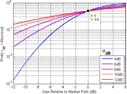
A lognormal model suits very well when there is LOS and the reflective paths are unimportant. In particular, if µ is the median value of the path loss (in dB) at a specified distance R from the transmitter, then the distribution xdB of the observed path losses at this distance have the
PDF(probability density function)
fR(xdB) =
1 √
2πσdB
e−(xdB−µ)/2σ2 (2.3)
Typical values for the standard deviation σdB range from 5 to 12 dB. The integration of Eq. 2.3
yields a CDF(cumulative density function) representation form. Figure 2.2 depicts the CDF for various σdB. From this representation, it is easy to find out the extra power margin that must be
included in the link budget to ensure a certain probability of outage.
Figure 2.2: A lognormal distribution can be used to model shadowing.
However, in most wireless scenarios, there are NLOS contributions and we are interested in including the effect of reflected waves, namely where there is relative motion of nearby objects. This kind of effect is commonly referred in the literature as fading and will be the topic of discussion of section 2.4.
2.4
Fading
Fading is caused by constructive and destructive interference of multipath waves and occurs when there is relative motion. It can be due to 2 situations. One of them has to do with multipath
2.4. FADING 19
and appears when there is relative motion of local reflecting objects(example: clouds) or motion of the terminal relative to these local objects. As a matter of fact, at a relatively large distance away from the transmitter, the received multipath amplitudes do not vary significantly. However, when the wavelengths are small compared to the distance(as is often the case), phase variations are highly sensitive to small position variations. Recalling that the received signal is the sum of all multipath components, we can understand that it can be easily distorted. In the vehicular radio scenario, sometimes it is enough to move just a few meters to notice deep signal attenuation or reinforcement. The smallest position variation can have a significant impact on the resulting sum of multipath components. The second situation is a direct consequence of Doppler effect. Such phenomena is also referred to in the literature as fast fading.
The power fluctuations of the received signal which are due to median path loss and shadowing can be easily corrected by a power control mechanism. Generally speaking, in the DL, the BS adjusts the transmitted power for each MT is such a way as to make up for those variations in the mean average power of the signal. That adjustment requires feedback from the MT since the BS must know the quality of the received signal. In this thesis it is assumed that the propagation losses due to median path loss and shadowing are perfectly compensated by the power control mechanisms. Thus, we shall simplify the mobile wireless channel model by considering just its fast fading distortive effect.
This section proceeds with further details on fast fading. We continue by presenting two statistical distributions for fast fading, namely the Rayleigh and Rice distributions, the difference being the relative contribution of LOS and NLOS contributions to the final received signal. Then a series of channel parameters such as coherence bandwidth and time are presented, hoping that they simplify the channel description for systems design purposes. These parameters are obtained by the amplitude correlation between the amplitude of the received signal (in time or frequency domains).
2.4.1
Statistical Distributions for fast fading
When there is no direct LOS, the complex envelope of N signal rays (reflections) is given by a sum of independent and identically distributed (i.i.d.) complex random variables:
˜ E = N X n=1 Enejθn (2.4)
Relative phases θn are assumed to be statistically independent and uniformly distributed over
[0, 2π]. Developing this expression yields the Rayleigh probability density function: fR(r) =
r σ2e
−r2/2σ2
(2.5) where σ2 is half the variance power in the complex envelope.
Rayleigh-fading model is well-suited for non line-of-sight (NLOS) situations because all paths (En’s) are relatively equal. However there is still an important case that must be discussed, which
is when there is LOS and reflections are relevant. The complex envelope translates the problem by regarding the complex received wave as the sum of the direct wave E0and N reflections:
˜ E = E0+ N X n=1 Enejθn (2.6)
Mathematically speaking, the amplitude of the complex envelope is said to be Rician dis-tributed : fR(r) =σr2e−(r 2+s2)/2σ2 I0(σrs2) with r ≥ 0 where s2 = |E
0|2 is the power in the direct path and I0(.) is the modified Bessel function of
zeroth order.
A key factor in the analysis is the ratio of the power in the direct path to the power in the reflected paths is referred to as Rician K-factor and is defined as the ratio of the power in the direct path to the power in the reflected paths:
K = s
2
PN n=1|En|2
(2.7)
Rician K-factor can be regarded as a link for generalizing of the the Rayleigh and Gauss distributions. Should s2→ 0 ,that is, K → 0, Rician reduces to Rayleigh distribution. If, on the
other side,PN
n=1|En|2→ ∞ then K → ∞ and we recover the gaussian distribution.
In the mobile communications context we are interested in providing a certain quality of service and that implies adding a fading margin to the link budget, so that the signal overcomes local losses for at less given percentage of time. Therefore the most practical graphics are the ones which represent amplitude distributions in cumulative probability distribution form, that is
P r(r < R) = Z R
0
fR(r)dr (2.8)
It requires design parameters such as required availability.
Figure 2.3: Amplitude distributions for a Rician Channel [20].
Fig. 2.3 makes it apparent that the probability of deep fades (which causes burst errors) diminishes as the K factor increases and is less common in Gauss channels that in Rayleigh ones.
2.4. FADING 21
2.4.2
Delay Spread, Coherence bandwidth and Frequency Selectivity
The correct description of the fading phenomena is very important, since it is the first step for projecting efficient mitigating techniques. For that it is useful to define parameters such as delay spread, coherence bandwidth and frequency selectivity.
We start by defining the autocorrelation function of the channel impulse response as [8]
R(τ1, τ2; ∆t) =
1
2E {h(t, τ1)h
∗(t + ∆t, τ
2)} (2.9)
where ()∗and E. denote complex conjugation and average, respectively. It it common practise to assume that there is no amplitude or phase correlation between individual replicas whose delays are τ1 and τ2. That is the case when echoes travel through paths which are not correlated.
This scenario is referred to as uncorrelated scattering (US) and its autocorrelation function is a simplification of Eq. 2.9:
R(τ1, τ2; ∆t) = ρ(∆t, τ1)δ(τ1− τ2) (2.10)
where ρ(∆t, τ ) represents the power spectral density of the delay [8]. Fortunately, most mobile radio channels are wide sense stationary (WSS) with respect to the time variable and, simulta-neously, of uncorrelated spreading in the delay variable. The combination of these 2 properties results in a class known as wide sense stationary uncorrelated scattering (WSSUS) channels. If we take the Fourier Transform of ρ(∆t, τ ) with respect to the ∆t, we end up with a function that describes the channel both in delay and Doppler frequency shift domains. That scattering function can be expressed as
S(τ1, fD) =
Z ∞
−∞
ρ(∆t, τ )e−j2πfD∆td∆t (2.11)
Eq. 2.11 is real and can be regarded as a measure for the average power per unit frequency, in the fD domain, as a function of the delay at the output of the channel. We can get further insight
by performing its integration with respect to the Doppler frequency shift:
ρ(τ ) = Z ∞
−∞
S(τ, fD)dfD (2.12)
Eq. 2.12 is the delay power spectrum (PDS) and reduces to ρ(∆t, τ ) when ∆t = 0. The PDS means the average power at the output of the channel as a function of the delay and can also be regarded as the mean of Eq.2.11 over all Doppler frequency shifts.
From 2.12 we can define two important design parameters: mean delay spread τ and rms delay spread, στ. The mean delay spread is given by
τ = R∞ 0 τ ρ(τ )dτ R∞ 0 ρ(τ )dτ (2.13) while the rms delay spread is defined as
στ = sR∞ 0 (τ − τ ) 2ρ(τ )dτ R∞ 0 ρ(τ )dτ (2.14) If the power delay profile of the channel is discrete and consists of Lp distinct components,
![Figure 1.1: There is a trend to move wireless systems to higher frequency bands so that higher bit rates can be offered [57].](https://thumb-eu.123doks.com/thumbv2/123dok_br/15992846.1103057/26.918.174.744.139.481/figure-trend-wireless-systems-higher-frequency-higher-offered.webp)


![Figure 1.4: The relay channel with three nodes[16].](https://thumb-eu.123doks.com/thumbv2/123dok_br/15992846.1103057/35.918.165.742.133.399/figure-the-relay-channel-with-three-nodes.webp)
![Figure 2.1: The channel distortion can be decomposed into 3 independent phenomena [7].](https://thumb-eu.123doks.com/thumbv2/123dok_br/15992846.1103057/41.918.148.762.242.461/figure-channel-distortion-decomposed-independent-phenomena.webp)
![Figure 2.3: Amplitude distributions for a Rician Channel [20].](https://thumb-eu.123doks.com/thumbv2/123dok_br/15992846.1103057/44.918.279.624.700.985/figure-amplitude-distributions-for-rician-channel.webp)


![Figure 3.5: Usage of antenna elements to direct the beampattern and avoid interferers[58].](https://thumb-eu.123doks.com/thumbv2/123dok_br/15992846.1103057/61.918.281.621.145.444/figure-usage-antenna-elements-direct-beampattern-avoid-interferers.webp)
