1
A Grid-Connected PV System Based on a
Multilevel Cascaded Inverter with a Single
and Three-Phase Two-Level Inverters
V. Fernão Pires* **, Joaquim Monteiro***, J. F. Silva****
*ESTSetúbal/Instituto Politécnico Setúbal, INESC-ID Lisboa, Portugal, [email protected]
** Centro de Engenharia para um Desenvolvimento Sustentável (SustainRD-IPS) ***ISEL – Polytechnic Institute of Lisboa, INESC-ID Lisboa, Portugal,
****DECC IST, Universidade de Lisboa, INESC-ID Lisboa, Portugal, [email protected]
Abstract- In this work a new multilevel cascaded inverter (MCI) based grid connected photovoltaic system is presented. The proposed MCI is based on a classic three-phase bridge inverter, where is connected the PV generator and three single-phase inverters. The asymmetry between the amplitude of the three phase bridge inverter DC source and the single phase inverter capacitor allows maximize the output levels voltage. In order to control this three-phase MCI a SPWM is used. The algorithm of this modulator will also be used to ensure the DC voltage balancing of the capacitors connected to the inverter. For this control strategy a sliding mode and PI linear controllers were also designed to obtain the modulator parameters. Simulation results are presented in order to confirm the proposed topology and the control adopted.
Keywords- Multilevel cascaded inverter; Photovoltaic System; SPWM modulator; PI linear controllers;
1. Introduction
Photovoltaic (PV) sources are rapidly growing in electricity markets due to several factors such as, declining cost of PV modules, increasing efficiency of PV cells and economics of scale [1, 2]. However, the successful use of the PV sources also depends, namely of their performance and power quality. In grid-connected photovoltaic systems, the power inverter can be considered as the main component. Thus, a variety of topologies have been proposed for this kind of applications, considering specifications as power, power quality and voltage level [3]. A multilevel power inverter, with the structure of the cascade H-bridge inverter, using only one DC source was also proposed [4-6]. This topology uses an H-bridge with a dc source and another H-bridge, where the dc voltage source is only a capacitor.
In this paper it is proposed a Multilevel Cascaded Inverter (MCI) connected to the grid, for photovoltaic systems. The proposed topology has one classical three H-bridge inverter, supplied by a dc voltage and three single-phase H-bridge inverter, with a capacitor as dc voltage supply. This system allows a maximization of the output voltage levels, since it the voltage of the single inverters adds half of the value of the three-phase voltage source inverter. In order to control this MCI structure two control loops are used. The SPWM modulator with PI linear controllers, for the three-phase inverter and the sliding mode control, to maintain the capacitor voltage balanced on the three single-phase inverters[7].The results are presented to verify the advantage of the proposed topology and the respective designed controller.
3
The grid-connected PV system used in this work is presented in Fig. 1. The power circuit consists of a PV string, a DC/DC power converter and a MCI structure, with one three-phase voltage source inverter and three single-phase inverters.
VS1 VS2 VS3 S11 S12 S13 S11 S12 S13 iPH i1N V3 V2 V1 S21 S22 S21 S22 S31 S32 S31 S32 S41 S42 S41 S42 VDC VDC 2 VDC 2 VDC 2 PV String S L DC/DC Converter R, L i1 i2 i3 DC/AC Converter
Figure 1. Proposed multilevel inverter cascaded topology connected a PV System
3. Control Strategy
The proposed MCI will be controlled by suitable controllers for the single-phase and the three phase inverters to ensure tracking of the d, q components of the three-phase current references (idref, iqref). Thus, since only reactive power can be supplied, the single-phase inverter will be considered to behave as a negative (or positive) inductor L. In order to ensure that the capacitor voltage is constant, a virtual resistor rL, given by
rL=K(vCref - vC), where K is a chosen parameter, inversely proportional to the inverter current iL maximum magnitude. The AC output voltage fundamental component of the single-phase inverter v1 is expressed as:
1 L L L
di
v L r i
dt
Using PWM to obtain v1 and being vPWM the three-level inverter switching voltage, the following relation must be achieved:
0 1 0
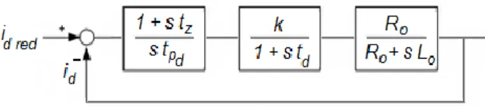
v Kv v i dt Li t T L T L C C PWM ref (2)To obtain a suitable L value controller consider that ac currents must be sinusoidal with slowly time varying magnitude, regarding the period T, and iq= LG(s), where G(s) is the converter transfer function. Therefore, we can design a relatively slow first order system (4) with time constant tp. The block diagram of the system controller related with id component, in Fig. 2. The id component error will control the modulation index
m of the SPWM used in the three-phase inverter, through the use of a PI compensator.
The block diagram of the system controller related with id component is presented in Fig. 3. From the closed loop transfer function (Fig. 2) the parameters of the PI controller can be obtained.
Fig. 2. Block diagram of the id current loop.
4. Results
In order to confirm the proposed system several tests have been made. The simulations were performed using MATLAB/Simulink and SimPowerSystems library. In table 1 the parameters of the system.
TABLE I.PARAMETERS OF THE SYSTEM
DC Source voltage 400 V
Capacitor voltage reference 200 V
Capacitors, C 10 mF
5
Grid AC voltage 120 V
Grid frequency 50 Hz
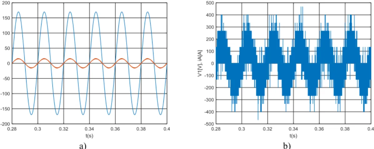
In figure 3 a) the results of the grid voltage and current are shown. From this result it is possible to verify that the multilevel inverter provides near sinusoidal currents. The output voltage of the MCI is presented in Fig. 3 b). As can be seen in this figure, the output voltage has seven levels. Fig. 4 shows the three-phase output currents waveforms. From this result it is possible to verify that the amplitude currents change for the desired value.
a) b)
Figure 3. a) Results of the grid voltage and current; b) Result of the output voltage
Figure 4. Result of the output currents waveforms for a change in the current reference.
5. Conclusion
This work presents a new multilevel cascaded inverter topology for a grid-connected photovoltaic system. This topology consists in one three-phase two-level voltage source
inverter and three two-level single-phase voltage source inverter connected in a cascaded structure. The PV generator is connected to the three-phase inverter while the single-phase inverters have a DC floating capacitor. To extend the number of voltage levels it was used different voltage values for the DC side of the inverters. A control system for the proposed converter was also proposed. This system consists in a sliding mode control, a PI compensator and a SPWM. The obtained results showed the effectiveness of the proposed topology and control system used.
References
1 A. Keyhani, M.N. Marwali, M. Dai, “Integration of Green and Renewable Energy in Electric Power Systems”, Wiley 2010.
2 S. Li, T.A. Haskew, D. Li, F. Hu “Integrating photovoltaic and power converter characteristics for energy extraction study of solar PV systems,” Renewable Energy, vol. 36, no. 12, pp. 3238-3245, 2011. 3 Y. Choi, J. Rayl, C. Tammineedi, J. R. S. Brownson “PV Analyst: Coupling ArcGIS with TRNSYS to assess distributed photovoltaic potential in urban areas,” Solar Energy, vol. 85, no. 11, pp. 2924-2939, November 2011.
4 JN. Chiasson, B. Ozpineci, 1.M. Tolbert, "A Five-Level Three-PhaseHybrid Cascade Multilevel Inverter Using a Single DCSource for a PM Synchronous Motor Drive", Applied PowerElectronics Conference and Exposition, pp. 1504-1507, March2007.
5 F. Khoucha, A Ales, A Khoudiri, K. Marouani, M.E.H. Benbouzid, A Kheloui, "A 7-Level Single DC Source Cascaded H-Bridge Multilevel Inverters Control Using Hybrid Modulation",International Conference on Electrical Machines, pp. 1-5,September 2010.
6 S. Vazquez, l I. Leon, 1.G. Franquelo, l l Padilla, l M. Carrasco, "DC-voltage-ratio control strategy for multilevelcascaded converters fed with a single dc source", IEEETransactions on Industrial ElectroniCS, vol. 56, no. 7, pp. 2513-2521, July 2009.
7 J. Fernando Silva, Sónia Ferreira Pinto, Advanced Control of Switching Power Converters, in Muhammad Rashid et al, editors: Power Electronics Handbook 3ed, Vol Chennai: Butterworth Heinemann, 2011, chapter 36, pp. 1037-1114D.