Automatic Sun-Tracker System for
Photo-Voltaic Plants
Joao M. G. Figueiredo
CEM-IDMEC, Universidade Évora, Mechatronics Group
R. Romão Ramalho, 59; 7000-671 Évora, Portugal
Phone/Fax number:+00351 266 745 300, e-mail: [email protected]
1. Introduction
According to market economy, the increasing worldwide demand for energy, forces a continuous rise on the price of fossil combustibles. In fact, it is expected in the near future, that the demand for energy will grow faster than the finding out of new available fossil resources (Khan et al., 2007).
This market behaviour brings a positive challenge to the scientific community as more funds are allocated for the research and development of new alternatives to the usual main energetic sources (fossil combustibles). In this context we have seen, in the last decades, to a concentrated focus on renewable energy research. Among these renewable energetic sources, the international scientific community has devoted intense efforts to wind, solar photovoltaic and biomass. Some investigations and hardware developments on wave energy have been led by Great Britain and Portugal (Wave-Energy-Centre). In this paper an intelligent sun-tracking system for efficiency maximization referring photovoltaic energy production is developed.
Nowadays photovoltaic energy has a low efficiency ratio concerning the complete distribution chain from production to consumption (ca. 12%). In optimized environments (materials, electric inverters, tracking systems, etc) an input of 1000W of solar incident energy can bring ca. 190W in electricity (efficiency of 19%). This low performance ratio implies big Earth surface consumption when it is intended to install industrial photovoltaic units with significant production impact (50MW – 100MW). Today it is being built in south Portugal a photovoltaic plant with 64MW production capacity which occupies an huge area of ca. 400 ha (4 Km2).
The more relevant side effect of the low efficiency of photovoltaic systems is its poor competition related to traditional combustibles in both economical and financial aspects. Owing to changes in the solar radiation energy and in the cell operating temperature, the output power of a solar array is not constant at all times. Consequently, a maximum solar power tracking controller is always needed in any scheme with solar cell arrays to ensure maximum utilization. Therefore, works to solve the problems on maximum power point (MPP) tracking have always been a hot topic for photovoltaic array utilization systems. A logical MPP tracking search algorithm using normalized current, voltage and power at the
work points, that corresponds to the maximum power point values for different operating conditions was early tested (Atlas, 1992), (Atlas, 1996). A on-line controller to track the MPPs under changing illumination was described in (Hua & Lin, 2003).
An optimization approach using fuzzy was given in (Benlarbi et al., 2004) for PV water pumping systems. Other MPP tracking controllers can be found in (Hua & Lin, 2004) and (Chen et al., 2004).
This paper focuses on the optimization of the electric energy production by photovoltaic cells through the development of an intelligent sun-tracking system. The developed tracking system is innovative in relation to the usual sun tracking systems available in the market. The usual available solutions for tracking systems rely on the knowledge of the geographical position of the solar panel on the earth surface. With this knowledge it is possible to know the relative position of the sun, on a time basis, according to the well known solar tables (Solardat). Modern solutions incorporate a GPS system to calculate the position of the solar panel on the Earth surface. The orientations to be followed by the photovoltaic panel, on a regular time-base, are then pre-programmed, on an open loop approach.
There are significant efforts on the optimization of sun tracking systems as it is documented by several registered international patents. These solutions are based either on the above described principle either on the quantification of the received solar energy, either on the maximization of the solar incident radiation through the use of light concentration lens or mirrors (Biee & Chace, 2009), (Rubio et al., 2007). The solution developed in this paper is innovative related to the above referred approaches as this system is autonomous regarding the information needed to process the optimal orientation and it is intelligent in a way that it monitors, on a real-time base, the photovoltaic energy production and it avoids systematic failures coming from changes on the assumed blind values (position, initial infrastructure orientation, cleanness of the photovoltaic cells, etc.).
2. System Description
2.1 Overall System Presentation
The overall system is presented in fig. 1. The complete strategy is composed by 5 sub-systems: 1) Electro-Mechanical Structure; 2) Control Unit; 3) Supervisory System; 4) Wind-meter; 5) Photovoltaic Park.
The developed tracking system searches the optimal orientation of a surface, related to the sun incident radiation. The global performance of the system is described below. The planar surface is composed by a photovoltaic cell which is motorized by 2-orthogonal axis. These two controlled DOF (Degrees Of Freedom) are managed by a PLC (Programmable Logic Controller) according to a search programme that compares the electric power produced by the photovoltaic cell in each correspondent orientation. The maximal power value is stored and the correspondent orientations on both motorized axis are stored. This new optimal orientation of the tracking system is then communicated to the industrial photovoltaic park in order to transfer the new optimal orientation to all PV-production panels.
2.2 Electro-Mechanical Structure
The operational subset of the tracking system, named Electro-Mechanical System, is presented in figs 2 and 3.
This structure has two DOF, motorized by stepper motors with incorporated encoders, in order to track exactly the prescribed path.
The mechanical system was designed using standard industrial Aluminium profiles in order to obtain a simple and economic structure.
The mechanical structure is mainly composed by Bosch-Profiles and Aluminium plates. The two motorized axis are composed by Step-motors assembled to Aluminium shafts. Figure 2 illustrates the several main components of the mechatronic system:
Part n. 6 = Step-Motor to control axis 1; Part n. 7 = Step-Motor to control axis 2; Part n. 8 = Photovoltaic cell (150mmx150mm).
Figure 3 details the two designed degrees of freedom (DOF).
2.3 Control Unit
The control unit is composed by a PLC system (Programmable Logic Controller). This control system has the complete operational management of the tracking system.
The main tasks performed by the system are: - Control of the two step motors;
- Processing the data from both encoders;
- Processing the voltage signal coming from the PV-Cell;
1 2 3 Internet GSM mobile network 5 4 1 2 3 Internet GSM mobile network 5 4
- Processing the data from the external proximity sensors that informs the system about the hard-home position reference.
This PLC controls directly the tracking system and commands all other PV-Panels, from the solar Park, through a Profibus-DP network (Siemens, 2001a).
Figure 4 shows an example of a solar park with motorized PV-Panels. Figure 5 illustrates the Profibus network implemented in this study.
7
8
6
Fig. 2. Electro-Mechanical System: Main Components
α2
α1
2.4 Supervisory System
A SCADA system (Supervisory Control And Data Acquisition) is implemented to monitor and supervise the tracking system.
A Supervisory Control and Data Acquisition (SCADA) System is used as an application development tool that enables system integrators to create sophisticated supervisory and control applications for a variety of technological domains, mainly in the industry field. The main feature of a SCADA system is its ability to communicate with control equipment in the field, through the PLC network. As the equipment is monitored and data is recorded, a SCADA application responds according to system logic requirements or operator requests. In the developed supervisory system the SCADA application manages the overall system dynamics.
The Communication flux between the supervisory system and the control unit is illustrated in fig. 5.
The SCADA PC is simultaneously a SCADA server and an internet server, as the implemented SCADA application is web enabled.
3. Experimental Prototype
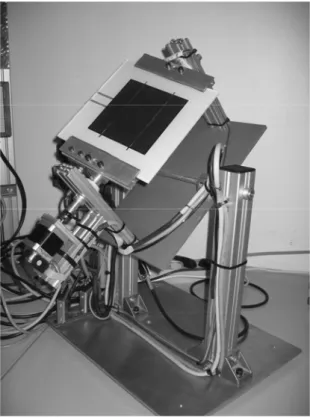
3.1 Physical Description
The prototype built followed the design presented in figure 2. This system incorporates a PV-cell 150mmx150mm, Pmax=1,12W, (Polycrystalline Silicon wafer) and the whole structure is made of aluminium alloy. In fig. 6 the global developed prototype is shown. The Fig. 4. Solar Park – motorized PV panels
control unit was developed using an industrial Siemens S7-300 PLC (Programmable Logic Controller).
The selected PLC system is a modular device that is constituted by the following modules: Slot1 = Power supply PS 307-2A
Slot2 = Processor CPU 315-2DP
Slot4 = Communication module CP 342 -5 Slot5 = Digital card DI8/DO8xDC24V/0,5A Slot6 = Analog card AI8 x12bit
Slot7 = Analog card AO4 x12bit
Slot8 = FM card – Counter Module (FM350) Slot9 = FM card – Counter Module (FM350) Slot10 = FM card – Stepper Motor (FM353) Slot11 = FM card – Stepper Motor (FM353)
Additionally, the PLC-tracker has a modem for GSM communication that provides the system capacity tocommunicate through the mobile phone network.
SCADA-PC Workstation SCADA-PC Workstation SCADA PC PLC Tracker PV-Panel 1 Profibus/ DP (RS 232/ MPI) PV-Panel 2 PV-Panel 3 PV-Panel 4
The driving unit is composed by two motorized axis, with the following characteristics: i) Axis 1
- Step motor: Nanotec ST4018L0804, 50Ncm; - Opt. Encoder: HP HEDL-5540 A14, 500 Pulses - Coupling unit: Oldham D5
- Proximity sensor: Omrom EA2 M8 PNP ii) Axis 2
- Step motor: Nanotec ST5918L1008, 170Ncm; - Gear box: Nanotec PLE40-1S-4
- Opt. Encoder: HP HEDL-5540 A14, 500 Pulses - Coupling unit: Oldham D25
- Proximity sensor: Omron EA2 M8 PNP Figure 6 shows a global view of the built Prototype.
3.2 Implemented Control Algorithm
The software used for the PLC programming was the Siemens Simatic Step 7 (Siemens, 2000). The designed control algorithm was implemented using the Ladder Logic – LAD (Siemens, 2001b). The developed control algorithm is illustrated in fig. 7.
Box0: After reset is activated, the system stores the PV-power generated in the actual position, Pactual, in the variable Pin. The system searchs its
reference-null position. It moves until it finds the hardhome position (both external proximity sensors on). In this position the system assumes the absolute orientation angles for both axis equal zero (α1 = α2 = 0). The maximal Power, Pmax is set to zero. Both counters, C1, C2, are loaded;
Box1: After start is activated, the system iniciates the search for the maximal power generated in axis 1, with an angle increment α10. The system stores the power generated in variable P1. Box2: If P1 < Pmax, the system goes to Box 4, and
follows for a new position;
Box3: If P1 > Pmax, this position is stored in the variables: α1max, α2max. The max. Power value, Pmax is actualized with the new Power value P1;
Box4: Counter for axis 1 is updated;
Box5: After all orientations for axis 1 are evaluated, regarding a fixed orientation for axis 2, axis 2 is positioned in a new position, with an angle increment α20, and axis 1 returns to its initial position α1=0. The system re-initiates the search for the optimal orientation of axis 1, regarding the new position of axis 2. The information flux returns to box 1.
Box6: After all orientations for axis 1 are evaluated, regarding all different positions of axis 2, the system compares the maximal power found (Pmax) with the initial Power generated, before the search process had begun (Pin). If the new Power value is greater than a pre-defined gain, this new correspondent orientation (α1max, α2max) is sent to all park panels. If the power gain is not enough, the new found position is not to follow by the other PV-panels. Box7: After a pre-defined time interval (K) the
tracker system initiates a new complete search process in both axis. The information flux returns to box 0.
reset
-Find and positioning the system in Hardhome ref. α1 = α2 = 0; - Pin = Pactual; - Pmax=0; - C1=5; C2=5 start -α1 = α1 + α10; - Read P1
P1O Pmax P1 > Pmax
-α1max = α1; -α2max = α2; - Pmax = P1 C1 = C1 - 1 C1 =1 C1 = 0 -α1 = 0;- C1 = 5; -C2 = C2 – 1 -α2 = α2 + α20; C2 =1 C2 = 0 T = K [s] T1 = 1 0 1 2 3 4 5 7
Pmax > Gmin x Pin Yes
- Send new orientation (α1max, α2max) to solar park; - Ok = 1 6 No Ok = 1
A short description of the tasks performed by the tracker controller, regarding the above referred algorithm, is described together with fig. 7.
3.3 SCADA Supervisory System
The Scada system was developed over the platform Siemens WinCC (Siemens, 2005). The SCADA system used to implement this monitoring and control strategy permits the selective access to the application, depending on the user’s responsibility degree. In this paper we developed three user levels: Operators, Supervisors and Administrators.
Several SCADA menus were built. The main characteristic of a SCADA Menu is to be simple, explicitand quick on transmitting the information to the operator or to the System administrator.
One of the developed Graphical User Interfaces (GUI) is shown in fig 8.
As this SCADA platform is web enabled, all the GUI displayed data is also on-line accessible through the internet.
In fig. 9 it is shown the developed main menu for the sun-tracker system. The on-line available information, referring actual data from the tracker unit is: actual position for both axis, actual PV-power generated, max. daily PV-power generated, actual efficiency ratio.
4. Conclusion
This paper focus the optimization of the electric energy production by photovoltaic cells through the development of an intelligent sun-tracking system. The developed tracking
system is innovative in relation to the usual sun tracking systems available in the market. In fact, the developed solution has many advantages in relation to similar existing devices, as this system is autonomous regarding the information needed to process the optimal orientation and is intelligent in a way that it performs on-line monitoring of the photovoltaic energy production.
The increase in power generation, in relation to other PV-systems, without tracking devices, is of similar magnitude (ca. 25%) as for other usual tracking solutions. However, this system has a relative advantage, as it measures exactly the controlled variable: the actual PV-power generation.
5. References
Atlas I, Sharaf A. (1992). “A Fuzzy Logic Power Tracking Controller for a Photovoltaic Energy Conversion Scheme”; Electr. Power Syst. Res. J., 1992; 25 (3); pp. 227-238 Atlas I, Sharaf A. (1996); “A Novel on-line MPP search algorithm for PV arrays”; IEEE Trans.
Energy Convers., 1996; 11 (4); pp. 748-754
Benlarbi K., Mokrani L., Nait-Said M. (2004), “A Fuzzy Global Efficiency Optimization of a Photovoltaic Water Pumping System”; Sol Energy 2004; 77; pp. 203-216.
Biee, S.; Chace JR, A. (2009). “Solar Tracking Reflector System for Structure Lighting”. European Patent Office, IPC: H01L31/052, EC: E04D13/03; US2009084431 (A1); 2009-04-02
Chen Y., Liu Y., Wu F. (2004) “Multi-Input Converter with Power Factor Correction, Maximum Power Point Tracking, and Ripple-free Input Currents”; IEEE Trans. Power Electron. 2004, 19 (3), pp. 631-639
Hua, C., Lin, J. (2003); “An on-line MPPT algorithm for rapidly changing illuminations of Solar arrays”; Renew Energy 2003; 28; pp. 1129-1142.
Hua C., Lin J. (2004) “A modified tracking algorithm for maximum power tracking of solar array”; Energy Conversion and Management 2004, Vol. 45, pp. 911-925.
Khan, N., Mariun, Z., Saleem, N., Abas, N. (2007). “Fossil Fuels, New Energy Sources and the Great Energy Crisis”. Renewable and Sustainable Energy Rev (2007), doi:10.1016/j.rser.2007.11 .011
http://solardat.uoregon.edu/ SolarPositionCalculatorhtml http://www.wave-energy-centre.org
Rubio, F., Ortega, M., Gordillo, F., López-Martínez, M. (2007). “Application of new control strategy for sun tracking”; Energy Conversion and Management, Vol. 48, Issue 7, July 2007, Pages 2174-2184.
Siemens (2000). System Software for S7-300 and S7-400 – Reference Manual, SIEMENS 08/2000; A5E00069892-02
Siemens (2001a). Simatic Net – NCM S7 for Profibus/ FMS. SIEMENS 12/2001. Siemens (2001b). Simatic S7-300 – Ladder Logic (LAD) for S7-300, SIEMENS, 2001. Siemens (2005). Simatic WinCC V6.0 SP2, SIEMENS, 2005.