Ricardo Alves Institute of Engineering University of the Algarve,
Campus da Penha 8005-139 Faro, Portugal
Luís Sousa Institute of Engineering University of the Algarve,
Campus da Penha 8005-139 Faro, Portugal
J.M.F. Rodrigues Institute of Engineering and Vision Laboratory, LARSyS,
University of the Algarve, 8005-139 Faro, Portugal
ABSTRACT
PoolLiveAid is an augmented reality tool designed to assist unskilled or amateur pool, or snooker or billiards players in predicting trajectories. A camera placed above the table acquires and processes the game on-the-fly. The system detects the table border, the ba
predictable trajectory of the white ball, and the ball directly in its trajectory. The output result is then forwarded to a projector, placed above the table, which then projects onto the snooker playable field. A skilled player can also save a specific layout of a move and load it later in order to achieve the best shot and practising.
Keywords
Augmented reality, computer vision, pool game.
1. INTRODUCTION
A pool game can be very challenging and tricky. The first contact with a game of pool can be very frustrating for an unskilled player, requiring many hours of practise to understand even the more basic and classical mechanics that exists in this game. In this paper we introduce a tool to assist mainly amateur pool players to train themselves by showing them on-the-fly in the pool table what will happen when the white ball is hit, helping the player to make the best decision, thus preventing him from playing countless times before getting it right. On the other hand, a skilled player can also save a specific layout of a move (or a group of moves) and load it later, project it directly onto the pool table in order to achieve the best shot and for practise.
This tool was developed to use the pool table as the interface. The system works with several varieties of tables, regardless of the cloth and colour of the ball (be it pool, snooker or billiard), with any camera that has HD feature, and a projector placed above the table. A camera is placed above the table for capturing and processing the game. The system
pool cue direction in order to compute the predictable trajectory of the white ball, and the ball directly in its trajectory. The output result is then forwarded to a projector, which then projects onto the snooker playable field.
There are several examples of tools connected, to some extent, to the game of pool, snooker or billiard. Denman et al. [DRK*03] presented three tools applied to footage from snooker broadcasts. The tools allow parsing a sequence based on geometry, without the need for deriving 3D information. They also allow events to be detected where an event is characterised by an object leaving the scene at a particular location. The last feature is a mechanism for summarising motion in a shot for use in a content based summary. Shen and Wu [SW10] also analyse videos. They did an automatic segmentation method of local peak edges to extract the table, and by using several pre-processing, morphological processing, clustering and HSV colour space they detect the ball to produce a 3D reconstruction of the game. Also related to video analysis for a 3D representation with different goals we have [HM07, HGB*10, PLC*11, LPC*11, LLX*12].
On a different level, Dussault et al. [DGM*09], Archibald et al. [AAG*10] and Landry et al. [LDM11] presented a computational system to create a robot capable of selecting and executing shots on a real table. Some of these authors, Leckie and Greenspan [LG06] presented a paper on the physics of the game of pool. One of these authors also has a web page with a tool somewhat similar to ours: ARPool is a projector-camera system that provides
Permission to make digital or hard copies of all or part of this work for personal or classroom use is granted without fee provided that copies are not made or distributed for profit or commercial advantage and that copies bear this notice and the full citation on the first page. To copy otherwise, or republish, to post on servers or to redistribute to lists, requires prior specific permission and/or a fee.
real-time feedback to a pool player directly on the surface of the table. However, to our knowledge, there are no publications on this tool (only the web-page). Also related to robotic pool, [NKH*11] presented a robot capable of playing on a normal-sized pool table using two arms. The robot can accurately locate the pool table, the balls on the table and the cue, and subsequently plans the next shot. In this case they use a green pool cue an almost white cloth (they also project trajectories on the table). Both robotic systems were tested under laboratory conditions (specific light conditions, etc.).
The main contributions of this paper are a system that: (a) works in real club/pub environment and can be mounted without the need for any changes in terms of table position, lights, etc. Only two supports are needed: one for the camera and one for the projector. (b) Uses the table as the surface for projection and interface with the user and (c) focuses mainly on amateur real players, who are learning to play, or players who want to see on-the-fly a mistake made in a previous play.
In section 2 we present table, ball and cue detection. In section 3 we compute the ball trajectories and explain how to project them onto the table. In section 4 tests and results from the two previous sections are presented. In section 5 we briefly show the main menus of the tool and finally in section 6 we present the conclusions and future work.
2. Table, ball and cue detection
As mentioned in the Introduction, the system was developed based on real pool tables, balls and pool cues. An HD camera was placed over the table, so as to capture the whole table (preferentially in the centre of the pool table). For the images and tests shown in this paper we used a simple HD webcam (around 25 fps), attached to the lamp that was over the table. The second component of the system is a quality projector (the lighter the surroundings, the better the projector has to be). This can be placed above the table, on the ceiling, projecting over the table, or in a hall near the table (near the ceiling), so the projector can project onto the entire table. In most of our tests, the last situation was the one used, due to the ceiling being too low.
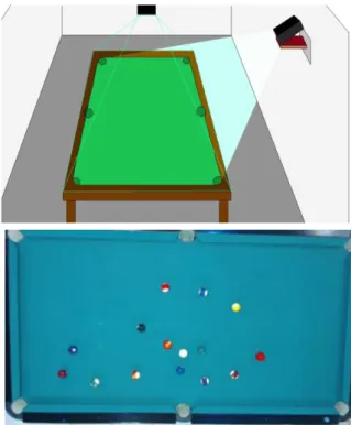
Figure 1, in the top, illustrates the system layout, with the position of the camera and projector. The bottom picture is an example of an image (frame) acquired by the camera. As can be seen, we do not need a perfect image of the table, only an image that catch the entire table.
In the rest of this section we will explain in detail the table boundaries, ball and cue detection.
Figure 1. In the top the system layout, camera and projector position in relation to the pool table. In
the bottom, the one acquired image (frame).
2.1.1 Pre-processing: Noise-reduction
A pool player needs to think of his/her next move, so he/she needs to have information on the next possible shot as early as possible, in order to give him/her a perception of what he/she is actually doing or aim to do. Nevertheless, information on the trajectory of a future shot is only needed when and every time movement stops. Based on that, a pool game has two distinct phases of information extraction: (a) detection of any motion, including the pool cue and (b) ball information when the game stops.
One of the main challenges while working with a real pool/snooker room is the noise in the captured frames due to different factors, e.g., the type of lightning. Upon this, we used two different noise-reduction algorithms, depending on which information was to be extracted: (a) motion or (b) balls.
Let be the RGB frame acquired in instance t and (x, y) the pixel coordinates within the frame. We used a (a) Gaussian Filter (G) [Rus11], with , when needing to analyse images in real time
= G( ) and we did a (b) frame time average [Rus11] when ball motion on the table was stopped (for pool table detection and balls detection), i.e.,
,
with N the number of frames to average (in present results N = 5) and the average result for instance t.
Figure 2 shows from top to bottom a section of a pool table image. The resulting image after applying the Gaussian filter ( ), as expected, a blur appeared, and after applying average filter ( ), we can see the improvement in table cloth.
All parameters used in the pre-processing stage ( and N) are calibrated only once in the setup stage, for each environment, and can be slightly different for each environment.
Figure 2. Top to bottom, a section of , the same section after and
2.1.2 Extracting Tables Boundaries
Extracting table boundaries with precision is extremely important. Trajectories of a ball are directly connected to these boundaries, causing a reflection on the trajectory which will be more perfect the more accurate a boundary is detected. If a boundary is just a few pixels wrong, the resultant trajectory will propagate the error, making it worse as distance to this boundary increases.
As long as a camera is fixed, boundaries never change (the table position never changes during a game). Based on this, they are only calculated once in the initial setup of the system.
Starting with an empty table, and from the middle of the image , which will or should be the centre of the table, going through top, bottom, left and right, these lines are extracted through edge detection using the Canny edge detector [Can86]
(with , and ) in being
(the average of the initial 10 images
acquired in the setup procedure) followed by the Hough Transform [DH72].
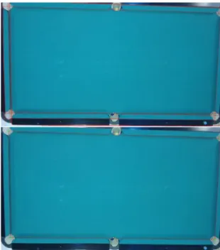
The results of a Hough transform are a set of
candidate lines for the ta n
Fig. 3 top. Every line detected this way is tested, checking if its angle is near ( ), in case it is a top or bottom table boundary, or if its angle is near ( ), in case it is a left or right table boundary, with . If a line succeeds this test, it is checked if there are other possible table boundaries near it. Inclination test is applied to every line near the first one detected, and if it succeeds, the average line of all lines detected will be considered to be a table boundary. After all this, with linear equations, all 4 corners of the table are found, see Fig. 3 bottom. If necessary, only if the automatic boundary
allow for the possibility in the setup procedure for the boundaries to be manually adjusted (slightly), using the setup menu interface and computers mouse.
If the camera is not in the centre of the table, or if necessary to detect the lines, or the final computed line is bigger than , then a perspective transform (e.g. [Rus11]) from the original image (video frame) pool table is required. This will decrease the performance of the system very slightly, once every operation (ball detection, trajectories, etc.) has to be affected by the same transformation. To simplify the explanation in the following sections and for the rest of the paper we ignore this transformation (i.e., we consider ).
Figure 3. Top, detected lines and in the bottom final automatic table boundaries extraction.
2.1.3 Movement Detection
After the detection of the table boundaries, movement detection is one of the more important functions to be computed. As previous explained, balls are only detected when movement on the table stops, avoiding the program to make unnecessary computations for the detection of the balls (see Section 2.1.5).
Movement detection also has a second purpose: pool cue detection (see Section 2.1.4). Obviously, the cue detection is more reliable if there were no balls on the table. As this is not possible, every time movement stops, a frame is taken by the camera, allowing it to be a reference for what it is in the table at that moment, we remember that in a pool/snooker game the player has a penalty if it touches or moves any ball. The frame is then
going to be used -trut for the
cue detection.
Movement detection is based on the subtracting the actual frame with the previous frame,
The output ( ), is converted to grayscale , and a threshold with the goal of creating a binary image is applied. All pixels with the level of gray above are assigned to 0 otherwise to 255, returning . The value of is automatically computed by calculating the maximum value that the histogram of E(x,y) during the setup stage changes more than 0.003% of the total of element in the playable field (we use 25 in the examples presented).
After this all pixel inside the table playable field (mark by the 4 red lines in Fig. 3 bottom) are counted, , if there are less then 0.003% of pixels with 255, it is considered that there is no more movement on the table, and the counted pixels are due to noise,
with
and W e H the weight and height of the playable field.
In summary, if , there is no
movement in the table, turning a movement flag OFF, otherwise turning it ON. Every time there is movement on the table, like e.g., cue striking a ball this flag is put to ON, but if set to OFF (by the above process) then we can conclude that movement on the table has stopped, a reference frame is taken and triggering ball detection algorithm.
2.1.4 Cue Detection
The cue information is only needed when the cue is relatively close to the white ball, as the cue is always
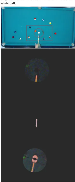
placed close to it when a player is preparing to strike the white ball. As result, information extracted is only considered if close, in a circular area, to the white ball.
Figure 4. Top to bottom, frame with the RoIs represented, image after subtraction with ,
the cue line detection and shot detection.
For the cue detection, the (a) current frame , Fig. 4-1st row, is subtracted to the reference frame , Fig. 1-2nd row, enabling the balls not to interfere with the cue detection. This difference is only done in a (b) small square region of interest (RoI) (to save CPU time) with dimension pixels, the
differences of the images are shown in Fig. 4-2nd row. For the final cue validation, a player hand must not be close to the white ball and for this reason we consider (c) a 2nd circular RoI, radius of
pixels, being r the radius of the white ball (see section 2.1.5 for r calculation). Following the same
principle and . In this
circular RoI usually no p , and if he put his hand in this area it is considered not the correct way to hold the cue (the system detect if there is a hand in this area and alert the user).
Being and from the converted
grayscale of , it is applied a (d) threshold (we used 50, this value was computed empirically) to binarise the result, obtaining a white shape Fig. 4-3rd row.
From this shape (e) we compute the middle line (the line that splits this shape into two), red line in Fig. 4-3rdrow. This line is considered to be the line of the
cue, where the tip of the cue is considered to be the point of the line closer to the white ball.
When a player shoots the white ball, the program needs to stop detecting the cue, in order to stop to show trajectory lines (see section 3). This is achieved, once again, by comparing the actual frame
with the reference frame .
Every time a new frame is acquired, an absolute subtraction is made ( ), in order to test what happens in the circular ball area. If the white ball is not stroke then the pixels value in the white ball area are (near) 0, since those areas of the images are equal, but if the white ball starts moving, then this area starts getting values different from 0, see Fig. 4 bottom.
Since the cue, can also be placed in contact and important to choose number of pixels that defines the white ball to be in movement ( ),
, being ( ) the centre of the circular RoI. We use to consider the ball in motion, see Fig. 4 bottom, once again this can be configured in the setup procedure, plus, depending of the camera used it is possible to compute de velocity of the strike (not implemented yet).
2.1.5 Detecting and Identifying the Ball
Every time movement stops,
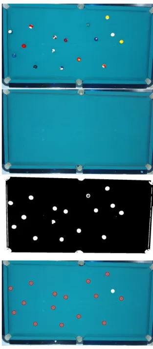
starts, consisting in comparing the actual average frame with the initial average frame that contains nothing but the empty table E(x,y) (Fig. 5, 1st and 2nd row respectively),
,
after which a binarisation is applied. Again, as in section 2.1.3, is converted to grayscale and every pixel with a value above 15 is put to white, obtaining , see Fig. 5-3rd row.
Using a contours finder [Rus11], we can know find various blobs which may, or not, be balls.
Figure 5. Top to bottom, , the reference frame , the subtracted binary image from the above images and the images with the detected
balls in red, plus the white.
Every blob detected is then considered to be a ball if it meets the three following parameters: (a) Ratio
( Hb) and width (Wb) is approximately 1,
.
approximately equal, , with the area of a circle, with ( ) the circle centre and r ( ) the radius of the circle,
with within
(c) Ratio ( ) between a circle and square area, ,
the last condition compares if the blob area verifies the circle and square areas relation. If these three relations are true, then the blob detected is considered to be a ball.
After detecting all the blobs, we must distinguish which of the blobs is the white (BW). This is achieved if both extracting contrast information (BC) and a ratio (BR) occur:
(a) For the contrast we check all the blobs (i) which is the one most differed from the background
BC
. (b) The ratio (BR)
area detected,
with
within The is the
converted to grayscale, and the was computed empirically. Once again this can be changed in the setup procedure of the system, but for all the tests done we always used .
The blob with the brightest area is the white ball, . Blobs that are not white will have few pixels in the bright area, while a white ball will have more pixels in the bright area.
As result of this operation, we obtain all balls detected with the white ball being distinguished from all the other as shown on Fig. 5 bottom. If we want to know which ball we are playing against, or make an automatic table of scoring (in the case of snooker), we can apply the above two principles (without applying the max) creating two tables were the colour are ordinates, this can also be complemented using thresholds in HSV colour space.
3. Ball Trajectories
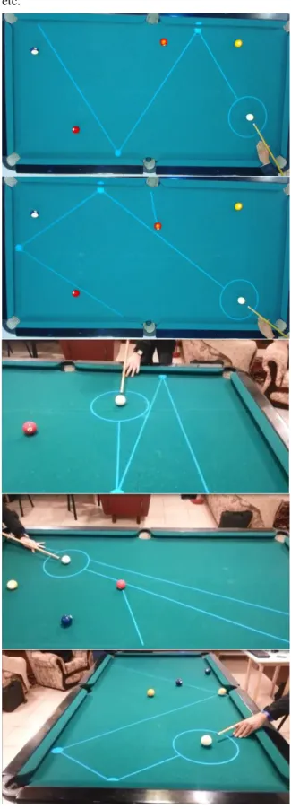
Ball trajectories shown in real time (see Fig. 7) can be computed after the cue and the white ball centre was detected, using simple and well known math formulas. The cue stick is represented by two points, and we can compute the correspondent line equation (m x + b) and the white ball by its radius r and centre point ( ).
The white ball is only going to be shot if the cue line intercepts any point of the white ball contour, i.e., if
points = , with
and
the points that contacts the white ball circular surface with the line of representing the cue. Thus, if any of those points ( are true, we can start calculating what would be the predictable trajectory, assuming the player will always try to hit its centre. It can be easily calculated applying the cue vector to its centre. All the different effects that a (semi-)professional player can do it is not considered for the module of the ball trajectories of the tool. This is a tool designer ball to go in a specific direction.
3.1.1 Reflection of the Ball-table
Having detected contact between the cue and ball, the t
maths. As shown in Fig. 6 top, being incident vector, we can obtain , which is vector normal to incident plane,
to achieve desired vector reflection it is used .
As the white ball centre never intercepts the boundaries, every reflection needs to be calculated using an auxiliary boundary moved the ball radius to the centre of the table, giving the result shown on Fig. 6 top.
3.1.2 Balls Interactions
Balls collisions are calculated using vectors. A vector containing the trajectory of a ball is applied to the tangent points of that ball, giving line L3 and L4 of Fig. 6 bottom. There are two interface points that we need to calculate before we can know what will happen to the intercepted ball.
First we need to know which of these lines, L3 and L4, intercepts of other ball and its interception
point, given by point a of Fig. 6-bottom. The second which is applied to the length of the intercepted ball radius to its centre, given by point b of Fig. 6-bottom.
The final trajectory, L2, is the normal of the vector given by point a and point b applied to the centre C2. The point d will make the contact with the point c.
in the top and collision between two balls in the bottom.
3.1.3 Projecting Ball and Trajectories to the
Table
Having all the balls detected and trajectories computed, the next step is to project everything onto the pool table. As mentioned before, we used a projector (see Fig. 1 top), basically matching the table dimensions in pixels (W, H) to the maximum resolution of the projector used. In other words, it is necessary to convert the computed trajectory and the
coordinates, applying a transformation matrix.
After this we create a back image where we render the balls positions; the white ball marked by a circle and the different trajectories. This can be seen in the computer in the background of Fig. 9 top.
Different options can be used, as for example using different colour for different trajectories,
or compute automatically here to put the cue if we want to put ball x in the side pocket y, save a game, or project onto the table the whole game (or part of the game), project a single continuous image with the ball position stored, to play again (and again) the
same move (this mainly for (semi-)professionals), etc.
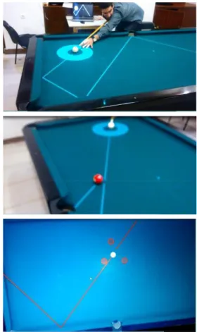
Figure 7. Some results of detected balls and proposed ball trajectories.
Augmented Reality Menus section (Section 5).
4. Tests and Results
Figures 7 and 9 show some examples of proposed trajectories. To test the system we invited two very inexperienced players (one male and one female) and we computed around 10 continue minutes of playing, at the same time doing the ground-truth of each play, and we analysed 3 main topics: (a) table boundaries detection, (b) detected balls and (c) expected trajectories.
4.1.1 Table Boundaries Detection
In this first test, we used two different tables in two different rooms, and we changed the lightning, turning on and off all different lights existing in the surroundings. As boundaries are usually the same colour as the table, there is almost no contrast between them, making it difficult to detect if the light in the surroundings is poor.
In well-lit surroundings, - all the usual lights turned on, the table boundaries were always automatically detected (100% of the times) with less than 3 pixel error that can be corrected with the computer mouse.
4.1.2 Ball Detection
Ball detection works very well when balls are not close to each other, with tiny errors on some balls that could not be measured. In a total of 194 balls detection test we obtained 0 false positives and 186 balls successfully detected (96%), where the 8 balls that were not detected were due to being too close to each other (in contact). Also, in this test, all the white balls were successfully detected with zero false positive white balls.
4.1.3 Trajectories
Trajectories predicted are related to the distance a ball can travel and how many bounces they have on a tested in 97% of the cases, where the 3% were due to some imperfections on the cue detection and due to the distance that the white ball would travel being high.
Balls that would bounce on one table were successfully tested in 77%, where the unsuccessful trajectories were due to the distance travelled, cue detection imperfections and spin gained or lost (due to speed) in a table boundary.
Similarly, only 54% of the balls travelled the predicted trajectory when bouncing twice on the table boundaries, due to what we previously stated. Interaction and reflection on other balls were 54% successful due to the errors previously stated and, possibly, to minimum errors on the ball positions.
5. Augmented Reality Menu
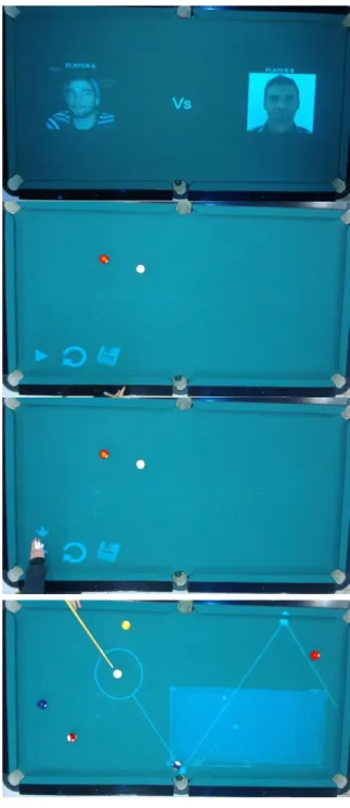
After setting up the system, done only once after installing the system, the tool is ready to work. The users can previously upload photos, or the system can download them directly from Facebook (given authorization by the user). The game starts by projecting the photos over the table (Fig. 8-1st row) when the two players put one hand over the photos an augmented reality pop-up menu appears (Fig. 8-2nd row). Balls can be placed on the table at any moment.
Three main features are shown (from left to right): (a) play with help, as shown in Fig. 7, (b) reload a previous play and (c) save a game/play. Several other menus are available or under construction. When we put the hand over the icon more than 3 second the option is activated, Fig. 8-3rd row, notice the arrow over the hand.
A player can use in-game features that enable the player to save a clip of his last move (option b), in order to see what went right or wrong, and show it on the table on-the-fly. A move can also be saved (option c), in XML format for it to be loaded later, allowing the player to practise that move later. The hand detection is based on the same principle of the ball detection. It is detected by comparing actual frame with the table reference frame . If the number of white pixels (PP) is higher than 95% of the icon circular area, then it assumes the player has selected the menu (this has to occur during 3 continuous seconds),
with
within the circular area
and are the dimensions of each icon of
the menu, and ( ) the centre
of each icon; .
The same process is used to disable the pop-up menu. If all icon areas have a PP value above for more than 10 second the menu is disabled. To pop-up the menus again, we have to put both hands again in the area where the faces are presented at the beginning. Despite this menu being quite easy to use, especially for people used to handling tablets, for instance, it can, however, be difficult for people not used to ICT. Taking this into account we are also studying the integration of previous works [SRB09, SFT*13] in hand and head gestures as interface to the tool.
6. Conclusion and Future work
In this paper, we presented a system that aids a beginner player to play pool. Using a standard HD
webcam, it allows detecting table boundaries, balls and cue stick. A projector, placed above the table, can show, in real time, the computed trajectory line in order to give a player a perception of what is going to happen in that particular move.
The system has two stages: (a) The setup, this is done only once, the first time that the system is mounted (or if the table changes position). In this stage there is a computer interface menu with all the parameters that can be adjusted. If any parameter adjustment is necessary, this is done only at this stage. After this (b) the running stage, every interaction with the system is done using the table as interface, i.e., using the augmented reality menu. There are no parameters to be adjusted at this stage.
The system works in real time, and all the tests and results showed were very good. In term of comparison with previous systems, it is quite difficult, because as for the best of our knowledge or ranking to test this algorithms, plus this is only system working in real time in real conditions, systems like [DRK*03, HM07, SW10, HGB*10, PLC*11, LPC*11, LLX*12] work on video taken from championship of pool or snooker, and [DGM*09, AAG*10, LDM11, NKH*11] work in a more or less controlled environment because of the robots.
We must also make a small note about the projector calibration. This is easily done using the menu of the projector itself, keeping only attention to the fact that the projected area must cover all playable area of the table. The projection in the table does not affect the balls and cue detection, as there is no projection when a move is made and only are projected again when all balls stopped (or when the player requests the menu, as referred in section 5). All frame acquisitions are done during these intervals.
In the near future we plan to enhance the ball detection, enabling it to detect balls when they are in contact with each other. We hope to enhance the cue detection, to develop a system to minimize the angular error on a table boundary and to reduce the error given by a player not shooting the ball in the centre of it, taking the speed of the strike into account. Also to improve the quality distortions in the camera optics should be handled.A further future goal is to finish (increase the number of options) and improve the augmented reality menu.
7. ACKNOWLEDGMENTS
This work was partly supported by the Portuguese Foundation for Science and Technology (FCT), project PEst-OE/EEI/LA0009/2011. We also thank Conceição Bravo for the English revising of the
paper and the Association Jovem Sambrasense for providing the pool table for the system development.
Figure 8. Some examples of the Augmented. Reality Menu.
8. REFERENCES
[AAG*10] Archibald, C., Altman, A. and Greenspan, M. and Shoham, Y. Computational Pool: A New Challenge for Game Theory Pragmatics. Magazine article from AI Magazine, vol. 31, no. 4, pp. 33-41, 2010.
[Can86] Canny, J. A computational approach to edge detection. IEEE Trans. Pattern Anal. Mach. Intell., vol. 8, no. 6, pp. 679-698, 1986.
[DRK*03] Denman, H., Rea, N., Kokaram, A. Content-based analysis for video from snooker broadcasts, Computer Vision and Image Understanding, vol. 92, no. 2 3, pp. 176-195, 2003. doi:10.1016/j.cviu.2003.06.005.
[DH72] Duda, R., Hart, P.: Use of the Hough transform to detect lines and curves in pictures. Comm. ACM, vol. 15, pp. 11-15, 1972.
[DGM*09] Dussault, J., Greenspan, M., Landry, J., Leckie, W., Godard, M., Lam, J. Computational and Robotic Pool. In Chap. XII of Digital Sport for Performance Enhancement and Competitive Evolution: Intelligent Gaming Technologies, IGI Global, pp. 194-209, 2009. doi: 10.4018/978-1-60566-406-4.ch012
[HM07] Hao, G., MacNamee, B. Using Computer Vision to Create a 3D Representation of a Snooker Table for Televised Competition Broadcasting. In Proc. 18th Irish Conf. on Artifical Intelligence & Cognitive Science, 2007. [HGB*10] Höferlin, M., Grundy, E., Borgo, R.,
Weiskopf, D., Chen, M., Griffiths, I.W., Griffiths, W. Video Visualization for Snooker Skill Training. Comput. Graph. Forum, vol. 29, no. 3, pp. 1053-1062, 2010.
[LDM11] Landry, J. and Dussault, J. and Mahey, P. Billiards: an optimization challenge, In Proc. 4th Int. Conf. on Computer Science and Software Engineering, Montreal, Quebec, Canada, pp. 129-132, 2011. doi: 10.1145/1992896.1992912 [LG06] Leckie, W. and Greenspan, M. An
event-based pool physics simulator. In Proc. 11th Int. Conf. on Advances in Computer Games, Taipei, Taiwan, Springer-Verlag LNCS 4250, pp. 247-262, 2006. doi: 10.1007/11922155_19
[LPC*11] Legg, P.A., Parry, M.L., Chung, D.H.S., Jiang, R., Morris, A., Griffiths, I.W., Marshall, D., Chen, M. Intelligent filtering by semantic importance for single-view 3D reconstruction from Snooker video. In Proc. 18th IEEE Int. Conf. on Image Processing, pp. 2385-2388, 2011. doi: 10.1109/ICIP.2011.6116122
[LLX*12] Ling, Y. Li. S., Xu, P. Zhou, B. The detection of multi-objective billiards in snooker game video. In Proc. 3rd Int. Conf. on Intelligent Control and Information Processing, pp. 594-596, 2012.
[NKH*11] Nierhoff, T., Kourakos, O., Hirche, S. Playing pool with a dual-armed robot," Robotics and Automation (ICRA), Proc. IEEE Int. Conf. on Robotics and Automation, pp.3445-3446, 2011. doi: 10.1109/ICRA.2011.5980204
[PLC*11] Parry, M.L., Legg, P.A., Chung, D.H.S., Griffiths, I.W., Chen, M. Hierarchical Event
Selection for Video Storyboards with a Case Study on Snooker Video Visualization, IEEE Tr. on Visualization and Computer Graphics, Vol.17, no.12, pp. 1747-1756, 2011. doi: 10.1109/TVCG.2011.208
[SRB09] Saleiro, M., Rodrigues, J. and du Buf, J.M.H. Automatic hand or head gesture interface for individuals with motor impairments, senior citizens and young children. In Proc. Int. Conf. on Software Development for Enhancing Accessibility and Fighting Info-exclusion, pp. 165-171, 2009.
[SFT*13] Saleiro, S., Farrajota, M., Terzic, K., Rodrigues, J.M.H, du Buf, J.M.H (2013) A biological and realtime framework for hand gestures and head poses, accepted for 15th Int. Conf. on HumanComputer Interaction
-Universal Access in Human-Computer Interaction Conf., 2013.
[SW10] Shen, W., Wu, L. A method of billiard objects detection based on Snooker game video. In Proc. 2nd Int. Conf. on Future Computer and Communication, vol. 2, pp. 251-255, 2010. doi: 10.1109/ICFCC.2010.5497393
[Rus11] Russ, J.C. The Image Processing Handbook, 6th Ed., CRC Press Inc., 2011.