Andreia Sofia Ladeira dos Santos Gouveia
Licenciatura em Ciências da Engenharia Química e Bioquímica
FACILITATED CO
2SEPARATION
MEMBRANES: MIXING CYANO AND
AMINO ACID-BASED IONIC LIQUIDS
Dissertação para obtenção do Grau de Mestre em Engenharia Química e Bioquímica
Orientador: Dra. Isabel Maria Delgado Jana Marrucho Ferreira, Investigadora Coordenadora, Laboratório de Termodinâmica
Molecular, ITQB-UNL
Presidente: Dra. Susana Filipe Barreiros Arguente: Dra. Luísa Alexandra Graça Neves
Vogal: Dra. Isabel Maria Delgado Jana Marrucho Ferreira
III
Universidade Nova de Lisboa
Faculdade de Ciências e Tecnologia
FACILITATED CO
2SEPARATION MEMBRANES: MIXING
CYANO AND AMINO ACID-BASED IONIC LIQUIDS
Andreia Sofia Ladeira dos Santos Gouveia
Licenciatura em Ciências da Engenharia Química e Bioquímica
Dissertação para obtenção do Grau de Mestre em Engenharia Química e
Bioquímica
Orientador:
Dra. Isabel Maria Delgado Jana Marrucho Ferreira, Investigadora
Coordenadora, Laboratório de Termodinâmica Molecular, ITQB-UNL
V
FACILITATED CO
2SEPARATION MEMBRANES: MIXING
CYANO AND AMINO ACID-BASED IONIC LIQUIDS
COPYRIGHT
Andreia Sofia Ladeira dos Santos Gouveia
Faculdade de Ciências e Tecnologia
Universidade Nova de Lisboa
VII
Agradecimentos
Ao longo deste desafiante percurso, que foi o Mestrado Integrado em Engenharia Química e Bioquímica, foram muitas as pessoas que me ajudaram a realizar esta etapa tão importante da minha formação académica, às quais quero deixar aqui o meu profundo agradecimento.
À minha orientadora, Dra. Isabel Marrucho, por me ter proporcionado as condições necessárias para a elaboração da minha dissertação e por me ter orientado e acompanhado ao longo de todo o trabalho. Agradeço também toda a simpatia e disponibilidade.
À Liliana Tomé, por ter sido muito importante e fundamental durante toda a dissertação, não só pelos conhecimentos transmitidos, que de certeza que irão ser indispensáveis no meu futuro, mas também pelo apoio e motivação, pelos conselhos, pela paciência, e por ter estado sempre presente e disponível para me ajudar em todas as ocasiões. Não tenho palavras que sejam suficientes para agradecer e transmitir toda a minha admiração. Obrigada por tudo!
À Catarina Florindo, por ter sido igualmente um apoio muito importante ao longo de toda a dissertação, por ter estado sempre disponível para me ajudar sempre que precisei, por todos os conselhos, pelos momentos de risadas e descontração, pelos desabafos, por tudo, um enorme obrigada.
À Karen João, ao Mateusz Marchel, ao David Patinha e ao Filipe Oliveira, por se terem demonstrado sempre disponíveis para me ajudar e por também terem proporcionado momentos de alegria durante estes últimos meses, que contribuíram, sem dúvida, para que esta fase final fosse muito menos stressante.
A todas as minhas colegas de curso, que para além de colegas, se tornaram amigas para a vida. À Sónia Branco, por ter sido um apoio muito importante principalmente ao longo destes últimos meses. Agradeço em especial, à Sofia Pires, por ter sido fundamental ao longo de todo este percurso académico, por me ter ajudado em todas as circunstâncias, por ter comemorado comigo os momentos bons e por ter estado ao meu lado em todos os momentos menos bons. Agradeço também à Bruna Pereira e à Carina Constantino, por terem sido excelentes amigas e companheiras de projeto. Obrigada pelos laços fortes de amizade criados e por terem estado sempre presentes em todos os momentos. Por fim, e não menos importante, quero agradecer à Sara Cândido, por ter sido também uma excelente amiga e companheira de trabalho ao longo destes cinco anos.
Ao Gonçalo, pelo amor e apoio incondicional, por estar sempre presente em todos os momentos, pela compreensão e paciência nos momentos mais stressantes, por me ter ajudado a ultrapassar momentos menos bons e por me apoiar e incentivar sempre a alcançar os meus objetivos. Obrigada por tudo!
À minha Família, em especial aos Meus Pais e ao Meu Irmão por acreditarem sempre em mim e naquilo que faço, por todos os ensinamentos de vida, por estarem sempre presentes e nunca me deixarem cair. Espero que esta etapa, que agora termino, possa, de alguma forma, retribuir e compensar todo o carinho, apoio e dedicação que, constantemente, me oferecem.
VIII
Our greatest weakness lies in giving up. The most certain way to succeed is always to try just one more time.
IX
Palavras-chave
Separação de Gases, Líquidos Iónicos, Membranas Líquidas Suportadas, Aminoácidos, Transporte Facilitado
Resumo
Nos últimos anos, tem sido feito um grande esforço no desenvolvimento de processos de separação de CO2 mais eficientes e sustentáveis. De entre as várias tecnologias utilizadas, as
tecnologias baseadas em membranas, em particular, membranas de líquidos iónicos suportados (SILMs), têm atraído bastante atenção essencialmente devido às propriedades únicas dos líquidos iónicos.
Neste trabalho, foi explorado o uso de misturas de líquidos iónicos como novas fases líquidas para SILMs, tendo em conta que os líquidos iónicos baseados em aminoácidos apresentam grupos amina "reativos" que podem atuar como transportadores de CO2, e que os
aniões que contêm grupos ciano que apresentam geralmente viscosidades baixas. Deste modo, foram preparadas misturas de seis líquidos iónicos com um catião em comum ([C2mim]+) e
diferentes aniões, tais como tricyanomethane ([C(CN)3]-), glycinate ([Gly]-), L-alaninate
([L-Ala]-), taurinate ([Tau]-), L-serinate ([L-Ser]-), L-prolinate ([L-Pro]-). Estas misturas foram
usadas como fases líquidas na preparação de membranas de líquidos iónicos suportados. Posteriormente, foram determinadas as propriedades de transporte (permeabilidade, difusão e solubilidade) ao CO2 e N2, a uma temperatura fixa e a vários diferenciais de pressão
trans-membranar, utilizando o método de time-lag. Uma vez que tanto a viscosidade do liquido iónico como o volume molar são parâmetros importantes que têm impacto sobre as propriedades de transporte dos gases nas SILMs, as propriedades termofísicas dos líquidos iónicos puros e das misturas preparadas, tais como, a viscosidade, a densidade e o índice de refração, foram também medidas para que as suas tendências pudessem ser avaliadas.
Os resultados obtidos neste trabalho evidenciam permseletividades de CO2/N2 acima da
XI
Keywords
CO2 Separation, Ionic Liquids, Mixtures, Supported Ionic Liquid Membranes, Amino acids,
Facilitated Transport
Abstract
A great deal of effort has been put on the development of efficient and sustainable CO2
separation processes. Among them, membrane-based technologies, in particular, supported ionic liquid membranes (SILMs) have recently attracted considerable attention owing to the unique properties of ionic liquids (ILs).
In this work, different IL + IL mixtures were explored as new liquid phases for SILMs.
Taking into account that ILs with amino acids present “reactive” amino groups that can work as CO2 carriers and that ILs combining cyano-functionalized anions present remarkably low
viscosities, mixtures of these ILs were studied. Thus, six ILs based on a common cation ([C2mim] +) and anions such as tricyanomethane ([C(CN)3]-), glycinate ([Gly]-), L-alaninate
([L-Ala]-), taurinate ([Tau]-), L-prolinate ([L-Pro]-) and L-serinate ([L-Ser]-) were mixed and SILMs
were prepared. The gas permeation properties (permeability, diffusivity and solubility) of CO2
and N2 were determined at a fixed temperature and different trans-membrane pressure
differentials, using a time-lag apparatus. Since the IL viscosity and molar volume are significant parameters that impact the gas permeation properties of SILMs, the thermophysical properties of the pure ILs and their mixtures, namely viscosity, density and refractive index, were also measured so that trends could be evaluated.
The results obtained in this work showed CO2/N2 permselectivities above the upper
bond for two facilitated SILMs, which clearly claim that mixing ionic liquids can be a promising strategy to design new liquid phases for CO2/N2 separation processes, since ILs offer
clear pathway to fine-tune their gas permeation properties as well as their CO2 separation
XIII
Contents
List of Figures ... XV List of Tables ... XXI List of Abbreviations ... XXIII List of Symbols ... XXV
1 Introduction ... 27
1.1 Motivation ... 29
1.2 CO2 Separation ... 32
1.2.1 Main Separation Technologies ... 32
1.3 Supported Liquid Membranes (SLMs)... 34
1.4 Ionic Liquids ... 35
1.5 Supported Ionic Liquid Membranes (SILMs) ... 36
1.6 Facilitated Supported Ionic Liquid Membranes ... 37
1.7 Ionic Liquid Mixtures... 39
1.8 Objectives ... 41
2 Synthesis and Characterization of AAILs ... 43
2.1 Materials and Synthesis of AAILs ... 45
2.1.1 Materials ... 45
2.1.2 Synthesis of amino acid ionic liquids (AAILs) ... 45
2.2 Thermogravimetric Analysis (TGA) ... 47
3 Thermophysical Characterization... 53
3.1 Preparation of the ionic liquid mixtures ... 56
3.2 Experimental Procedure ... 58
3.2.1 Viscosity and density measurements ... 58
3.2.2 Refractive Index measurements ... 58
3.3 Results and Discussion ... 59
3.3.1 Thermophysical properties for pure ILs and their mixtures ... 59
3.3.1.1 Density measurements ... 59
3.3.1.2 Viscosity measurements ... 70
3.3.1.3 Refractive Index measurements ... 78
4 Gas Permeation Properties ... 87
XIV
4.2 Gas permeation measurements ... 91
4.3 Results and Discussion ... 93
4.3.2 Gas Permeability ... 94
4.3.3 Gas Diffusivity ... 100
4.3.4 Gas Solubility ... 104
4.3.5 CO2 separation performance ... 108
5 Final Remarks ... 113
5.1 Conclusions and Future Work ... 115
6 References ... 117
7 Appendixes ... 125
7.1 Appendix 1 ... 127
7.2 Appendix 2 ... 133
7.3 Appendix 3 ... 141
7.4 Appendix 4 ... 143
7.5 Appendix 5 ... 147
7.6 Appendix 6 ... 149
7.7 Appendix 7 ... 151
7.8 Appendix 8 ... 153
XV
List of Figures
Figure 1.1 - Schematic representation of pre-combustion CO2 capture.4 ... 30
Figure 1.2 - Schematic representation of post-combustion CO2 capture.4 ... 30
Figure 1.3 - Schematic representation of CO2 capture by oxy-fuel combustion.4 ... 31
Figure 1.4 - Schematic of membrane gas separation. ... 33
Figure 1.5 - Scheme of the gas transport mechanism through supported liquid membranes. .... 34
Figure 1.6 – Schematic illustration of facilitated transport of CO2 in SILMs. ... 38
Figure 1.7 - Chemical structures of ionic liquids used in this work. ... 40
Figure 2.1 - AAILs synthesis method. ... 46
Figure 2.2 - Pure imidazolium-based AAILs at room temperature after the drying procedure. 46 Figure 2.3 - TGA 2950/Q500 analyzer. ... 47
Figure 2.4 - TGA thermogram of the pure [C2mim][C(CN)3]... 49
Figure 2.5 - Derivative weight (%/min) of the pure [C2mim][C(CN)3] as a function of temperature (T). ... 49
Figure 2.6 – TGA thermogram of [C2mim][C(CN)3]0.5[L-Ala]0.5 mixture. ... 50
Figure 2.7- Derivative weight (%/min) of [C2mim][C(CN)3]0.5[L-Ala]0.5 mixture as a function of temperature (T). ... 50
Figure 2.8 - TGA thermogram of the pure [C2mim][L-Ala]. ... 51
Figure 2.9 - Derivative weight (%/min) of the pure [C2mim][L-Ala] as a function of temperature (T). ... 51
Figure 3.1 – Chemical structures of ions used and composition matrix of the prepared IL + IL mixtures. ... 56
Figure 3.2 - SVM 3000 Anton Paar rotational Stabinger viscometer-densimeter ... 58
Figure 3.3 - Anton Paar Refractometer Abbemat 500 ... 58
Figure 3.4 - Densities (ρ) of the pure ionic liquids measured in this work as a function of temperature (T): [C2mim][C(CN)3] (×), [C2mim][Gly] (□), [C2mim][L-Ala] (▲), [C2mim][Tau] (○), [C2mim][L-Ser] (●), [C2mim][L-Pro] (■). ... 59
Figure 3.5 - Densities (ρ) of the ionic liquids mixtures measured in this work as a function of temperature (T): [C2mim][C(CN)3]0.25[Gly]0.75 (□), [C2mim][C(CN)3]0.25[L-Ala]0.75 (▲), [C2mim][C(CN)3]0.25[Tau]0.75 (○), [C2mim][C(CN)3]0.25[L-Ser]0.75 (●), [C2mim][C(CN)3]0.25 [L-Pro]0.75 (■). ... 60
XVI
Figure 3.7 - Densities (ρ) of the ionic liquids mixtures measured in this work as a function of temperature (T): C2mim][C(CN)3]0.75[Gly]0.25 (□), [C2mim][C(CN)3]0.75[L-Ala]0.25 (▲),
[C2mim][C(CN)3]0.75[Tau]0.25 (○), [C2mim][C(CN)3]0.75[L-Ser]0.25 (●), [C2mim][C(CN)3]0.75
[L-Pro]0.25 (■). ... 61
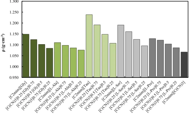
Figure 3.8 - Density values of the prepared IL mixtures with different compositions at T = 318.15 K. ... 62 Figure 3.9 - Molar Volumes (Vm) of the pure ionic liquids measured in this work as a function
of temperature (T): [C2mim][C(CN)3] (×), [C2mim][Gly] (□), [C2mim][L-Ala] (▲),
[C2mim][Tau] (○), [C2mim][L-Ser] (●), [C2mim][L-Pro] (■). ... 65
Figure 3.10 - Molar Volumes (Vm) of the ionic liquids mixtures measured in this work as a
function of temperature (T): [C2mim][C(CN)3]0.25[Gly]0.75 (□), [C2mim][C(CN)3]0.25[L-Ala]0.75
(▲), [C2mim][C(CN)3]0.25[Tau]0.75 (○), [C2mim][C(CN)3]0.25[L-Ser]0.75 (●),
[C2mim][C(CN)3]0.25[L-Pro]0.75 (■). ... 66
Figure 3.11 - Molar Volumes (Vm) of the ionic liquids mixtures measured in this work as a
function of temperature (T): C2mim][C(CN)3]0.5[Gly]0.5 (□), [C2mim][C(CN)3]0.5[L-Ala]0.5 (▲),
[C2mim][C(CN)3]0.5[Tau]0.5 (○), [C2mim][C(CN)3]0.5[L-Ser]0.5 (●), [C2mim][C(CN)3]0.5[L-Pro]0.5
(■). ... 66 Figure 3.12 - Molar Volumes (Vm) of the ionic liquids mixtures measured in this work as a
function of temperature (T): C2mim][C(CN)3]0.75[Gly]0.25 (□), [C2mim][C(CN)3]0.75[L-Ala]0.25
(▲), [C2mim][C(CN)3]0.75[Tau]0.25 (○), [C2mim][C(CN)3]0.75[L-Ser]0.25 (●),
[C2mim][C(CN)3]0.75[L-Pro]0.25 (■). ... 67
Figure 3.13 - Excess molar volumes of the ionic liquid mixtures at 318.15K: C2mim][C(CN)3][Gly] (□), [C2mim][C(CN)3][L-Ala] (▲), [C2mim][C(CN)3][Tau] (○),
[C2mim][C(CN)3][L-Ser] (●), [C2mim][C(CN)3]L-Pro] (■). ... 69
Figure 3.14 - Measured viscosities (η) of the pure ionic liquids studied in this work as a function of temperature (T): [C2mim][C(CN)3] (×), [C2mim][Gly] (□), [C2mim][L-Ala] (▲),
[C2mim][Tau] (○), [C2mim][L-Ser] (●), [C2mim][L-Pro] (■). ... 70
Figure 3.15 - Measured viscosities (η) of the ionic liquids mixtures studied in this work as a function of temperature (T): [C2mim][C(CN)3]0.25[Gly]0.75 (□), [C2mim][C(CN)3]0.25[L-Ala]0.75
(▲), [C2mim][C(CN)3]0.25[Tau]0.75 (○), [C2mim][C(CN)3]0.25[L-Ser]0.75 (●),
[C2mim][C(CN)3]0.25[L-Pro]0.75 (■). ... 71
Figure 3.16 - Measured viscosities (η) of the ionic liquids mixtures studied in this work as a function of temperature (T): C2mim][C(CN)3]0.5[Gly]0.5 (□), [C2mim][C(CN)3]0.5[L-Ala]0.5 (▲),
[C2mim][C(CN)3]0.5[Tau]0.5 (○), [C2mim][C(CN)3]0.5[L-Ser]0.5 (●), [C2mim][C(CN)3]0.5[L-Pro]0.5
XVII
(▲), [C2mim][C(CN)3]0.75[Tau]0.25 (○), [C2mim][C(CN)3]0.75[L-Ser]0.25 (●),
[C2mim][C(CN)3]0.75[L-Pro]0.25 (■). ... 72
Figure 3.18 - Viscosity comparison for all the ionic liquid series at T = 318.15 K. ... 73 Figure 3.19 - Calculated activation energy (Ea) values of ionic liquid series studied in this work at 318.15K: [C2mim][C(CN)3][Gly] (□), [C2mim][C(CN)3][L-Ala] (▲), [C2mim][C(CN)3][Tau]
(○), [C2mim][C(CN)3][L-Ser] (●), [C2mim][C(CN)3][L-Pro] (■). ... 76
Figure 3.20 - Viscosity deviations of the ionic liquid mixtures at 318.15 K: C2mim][C(CN)3][Gly] (□), [C2mim][C(CN)3][L-Ala] (▲), [C2mim][C(CN)3][Tau] (○),
[C2mim][C(CN)3][L-Ser] (●), [C2mim][C(CN)3][L-Pro] (■). ... 77
Figure 3.21 - Measured refractive indices (nD) of the pure ionic liquids studied in this work as a
function of temperature (T): [C2mim][C(CN)3] (×), [C2mim][Gly] (□), [C2mim][L-Ala] (▲),
[C2mim][Tau] (○), [C2mim][L-Ser] (●), [C2mim][L-Pro] (■). ... 78
Figure 3.22 - Measured refractive indices (nD) of the ionic liquids mixtures studied in this work
as a function of temperature (T): [C2mim][C(CN)3]0.25[Gly]0.75 (□), [C2mim][C(CN)3]0.25
[L-Ala]0.75 (▲), [C2mim][C(CN)3]0.25[Tau]0.75 (○), [C2mim][C(CN)3]0.25[L-Ser]0.75 (●),
[C2mim][C(CN)3]0.25[L-Pro]0.75 (■). ... 78
Figure 3.23 - Measured refractive indices (nD) of the ionic liquids mixtures studied in this work
as a function of temperature (T): [C2mim][C(CN)3]0.5[Gly]0.5 (□), [C2mim][C(CN)3]0.5[L-Ala]0.5
(▲), [C2mim][C(CN)3]0.5[Tau]0.5 (○), [C2mim][C(CN)3]0.5[L-Ser]0.5 (●), [C2mim][C(CN)3]0.5
[L-Pro]0.5 (■). ... 79
Figure 3.24 - Measured refractive indices (nD) of the ionic liquids mixtures studied in this work
as a function of temperature (T): [C2mim][C(CN)3]0.75[Gly]0.25 (□), [C2mim][C(CN)3]0.75
[L-Ala]0.25 (▲), [C2mim][C(CN)3]0.75[Tau]0.25 (○), [C2mim][C(CN)3]0.75[L-Ser]0.25 (●),
[C2mim][C(CN)3]0.75[L-Pro]0.25 (■). ... 79
Figure 3.25 - Measured free molar volumes (fm) of the pure ionic liquids studied in this work as
a function of temperature (T): [C2mim][C(CN)3] (×), [C2mim][Gly] (□), [C2mim][L-Ala] (▲),
[C2mim][Tau] (○), [C2mim][L-Ser] (●), [C2mim][L-Pro] (■) ... 81
Figure 3.26 - Measured free molar volumes (fm) of the ionic liquids mixtures studied in this
work as a function of temperature (T): [C2mim][C(CN)3]0.25[Gly]0.75 (□),
[C2mim][C(CN)3]0.25[L-Ala]0.75 (▲), [C2mim][C(CN)3]0.25[Tau]0.75 (○), [C2mim][C(CN)3]0.25
[L-Ser]0.75 (●), [C2mim][C(CN)3]0.25[L-Pro]0.75 (■). ... 81
Figure 3.27 - Measured free molar volumes (fm) of the ionic liquids mixtures studied in this
work as a function of temperature (T): [C2mim][C(CN)3]0.5[Gly]0.5 (□), [C2mim][C(CN)3]0.5
[L-Ala]0.5 (▲), [C2mim][C(CN)3]0.5[Tau]0.5 (○), [C2mim][C(CN)3]0.5[L-Ser]0.5 (●),
[C2mim][C(CN)3]0.5[L-Pro]0.5 (■). ... 82
Figure 3.28 - Measured free molar volumes (fm) of the ionic liquids mixtures studied in this
XVIII
[C2mim][C(CN)3]0.75[L-Ala]0.25 (▲), [C2mim][C(CN)3]0.75[Tau]0.25 (○), [C2mim][C(CN)3]0.75
[L-Ser]0.25 (●), [C2mim][C(CN)3]0.75[L-Pro]0.25 (■). ... 82
Figure 3.29 – Experimental and literature density values of the pure amino acid-based ionic liquids studied at T = 318.15 K. ... 84 Figure 3.30 - Experimental and literature viscosity values of the pure amino acid-based ionic liquids studied at T = 318.15 K. ... 84 Figure 3.31 - Experimental and literature refractive index values of the pure amino acid-based ionic liquids studied at T = 318.15 K. ... 85 Figure 4.1 – Vacuum chamber a) before and b) after the IL sample impregnation. ... 90 Figure 4.2 - Chemical structures of ions and composition matrix of the IL + IL mixtures tested as liquid phases in SILMs. ... 90 Figure 4.3 - Time-lag apparatus. P represents the pressure sensors, V the manual valves, VF the feed tank, VP the permeate tank and T a thermostatic air bath. ... 91 Figure 4.4 - Stainless steel flat-type permeation cell used in this work. ... 92 Figure 4.5 - Gas permeabilities at T = 318.15 K and different feed pressures: [C2mim][C(CN)3]
(CO2) (■), [C2mim][C(CN)3] (N2) (■), [C2mim][C(CN)3]0.5[Gly]0.5 (CO2) (■),
[C2mim][C(CN)3]0.5 [Gly]0.5 (N2) (■) ... 96
Figure 4.6 - Gas permeabilities at T = 318.15 K and different feed pressures: [C2mim][C(CN)3]
(CO2) (■), [C2mim][C(CN)3] (N2) (■), [C2mim][C(CN)3]0.5[L-Ala]0.5 (CO2) (■),
[C2mim][C(CN)3]0.5 [L-Ala]0.5 (N2) (■) ... 96
Figure 4.7 - Gas permeabilities at T = 318.15 K and different feed pressures: [C2mim][C(CN)3]
(CO2) (■), [C2mim][C(CN)3] (N2) (■), [C2mim][C(CN)3]0.5[Tau]0.5 (CO2) (■),
[C2mim][C(CN)3]0.5 [Tau]0.5 (N2) (■) ... 97
Figure 4.8 - Gas permeabilities at T = 318.15 K and different feed pressures: [C2mim][C(CN)3]
(CO2) (■), [C2mim][C(CN)3] (N2) (■), [C2mim][C(CN)3]0.5[L-Ser]0.5 (CO2) (■),
[C2mim][C(CN)3]0.5 [L-Ser]0.5 (N2) (■) ... 97
Figure 4.9 - Gas permeabilities at T = 318.15 K and different feed pressures: [C2mim][C(CN)3]
(CO2) (■), [C2mim][C(CN)3] (N2) (■), [C2mim][C(CN)3]0.5[L-Pro]0.5 (CO2) (■),
[C2mim][C(CN)3]0.5 [L-Pro]0.5 (N2) (■) ... 98
Figure 4.10 - CO2 permeability values through the prepared SILMs at T = 318.15 K and 2.5 kPa
of feed pressure as a function of viscosity (η). ... 99 Figure 4.11 - CO2 diffusivity values through the prepared SILMs at T = 318.15 K and 2.5 kPa
of feed pressure as a function of viscosity (η). ... 101 Figure 4.12 – Experimental CO2 diffusivities in the SILMs as a function of IL viscosity
measured at T = 318.15 K. ... 103 Figure 4.13 - CO2 solubilities (m3 (STP) m-3 Pa-1) in the prepared SILMs as a function of feed
[L-XIX
Ala]0.5 (■), [C2mim][C(CN)3]0.5[Tau]0.5 (■), [C2mim][C(CN)3]0.5[L-Ser]0.5 (■),
[C2mim][C(CN)3]0.5[L-Pro]0.5 (■). ... 106
Figure 4.14 - CO2/N2 permselectivities through the prepared SILMs in function of feed pressure
(kPa): [C2mim][C(CN)3] (×), [C2mim][C(CN)3]0.5[Gly]0.5 (□), [C2mim][C(CN)3]0.5[L-Ala]0.5
(▲), [C2mim][C(CN)3]0.5[Tau]0.5 (○), [C2mim][C(CN)3]0.5[L-Ser]0.5 (●), [C2mim][C(CN)3]0.5
[L-Pro]0.5 (■). ... 110
Figure 4.15 - CO2 separation performance of the SILMs studied at T = 318.15 K and 2.5 of feed
pressure potted on CO2/N2 Robeson plot. Data are plotted on a log–log scale and the upper
bound is adapted from Robeson98 Literature data reported for other supported ionic liquid
membranes are also plotted.7, 45, 47, 50-54, 57, 89, 99 ... 111
Figure 7.1 - 1H-NMR spectrum of [C
2mim][Gly] in DMSO-d6. ... 127
Figure 7.2 - 13C-NMR spectrum of [C
2mim][Gly] in DMSO-d6. ... 127
Figure 7.3 - 1H-NMR spectrum of [C
2mim][L-Ala] in DMSO-d6. ... 128
Figure 7.4 - 13C-NMR spectrum of [C2mim][L-Ala] in DMSO-d6. ... 128
Figure 7.5 - 1H-NMR spectrum of [C
2mim][Tau] in DMSO-d6. ... 129
Figure 7.6 - 13C-NMR spectrum of [C
2mim][Tau] in DMSO-d6. ... 129
Figure 7.7 -1H-NMR spectrum of [C2mim][L-Ser] in DMSO-d6. ... 130
Figure 7.8 - 13C-NMR spectrum of [C
2mim][L-Ser] in DMSO-d6. ... 130
Figure 7.9 -1H-NMR spectrum of [C
2mim][L-Pro] in DMSO-d6. ... 131
Figure 7.10 - 13C-NMR spectrum of [C
2mim][L-Pro] in DMSO-d6. ... 131
Figure 7.11 – TGA thermogram of the pure [C2mim][Gly]. ... 133
Figure 7.12- Derivative weight (%/min) of the pure [C2mim][Gly] as a function of temperature
(T). ... 133 Figure 7.13 - TGA thermogram of the pure [C2mim][Tau]. ... 134
Figure 7.14 - Derivative weight (%/min) of the pure [C2mim][Tau] as a function of temperature
(T). ... 134 Figure 7.15 - TGA thermogram of the pure [C2mim][L-Ser]. ... 135
Figure 7.16 - Derivative weight (%/min) of the pure [C2mim][L-Ser] as a function of
temperature (T). ... 135 Figure 7.17 - TGA thermogram of the pure [C2mim][L-Pro]. ... 136
Figure 7.18 - Derivative weight (%/min) of the pure [C2mim][L-Pro] as a function of
temperature (T). ... 136 Figure 7.19 - TGA thermogram of the [C2mim][C(CN)3]0.5[Gly]0.5 mixture. ... 137
Figure 7.20 - Derivative weight (%/min) of the [C2mim][C(CN)3]0.5[Gly]0.5 mixture as a
XX
Figure 7.22 - Derivative weight (%/min) of the [C2mim][C(CN)3]0.5[Tau]0.5 mixture as a
function of temperature (T). ... 138 Figure 7.23 - TGA thermogram of the [C2mim][C(CN)3]0.5[L-Ser]0.5 mixture. ... 139
Figure 7.24 - Derivative weight (%/min) of the [C2mim][C(CN)3]0.5[L-Ser]0.5 mixture as a
function of temperature (T). ... 139 Figure 7.25 - TGA thermogram of the [C2mim][C(CN)3]0.5[L-Pro]0.5 mixture. ... 140
Figure 7.26 - Derivative weight (%/min) of the [C2mim][C(CN)3]0.5[L-Pro]0.5 mixture as a
XXI
List of Tables
Table 2.1 – Onset (T5%) and decomposition (Tdeg 1 and Tdeg 2) temperatures of the pure ILs and
their mixtures. ... 48
Table 3.1 - Thermophysical properties, viscosity (η), density(ρ),and calculated molar volume (Vm), at 293.15 K as well as water contents of the pure ionic liquids and their mixtures studied in this work. ... 57
Table 3.2 - Fitted parameters of the linear expression given by Equation (3.2) and respective correlation coefficient, R2. ... 63
Table 3.3 – Thermal expansion coefficients (αP) of the pure ionic liquids studied in this work, at atmospheric pressure. ... 64
Table 3.4 - Fitted parameters of VFT expresson given by Equation 3.6 and activation energy values at T = 318.15 K. ... 75
Table 3.5 - Comparison of density (ρ) 81, viscosity (η) 81 and refractive index (n D) 81 values of the pure ionic liquids measured in this work with those from literature at T = 318.15 K. ... 83
Table 4.1 – Thermophysical Properties (at T = 318.15 K) and water contents of pure [C2mim][C(CN)3] and IL mixtures used to prepare the SILMs studied. ... 93
Table 4.2 – Gas permeabilities at T = 318.15 K and different feed pressures. ... 94
Table 4.3 - CO2 diffusivity values through the prepared SILMs at T = 318.15 K and 2.5 kPa of feed pressure. ... 101
Table 4.4 - CO2 diffusivity values through the prepared SILMs at T = 318.15 K and 100 kPa of feed pressure. ... 103
Table 4.5 – CO2 Solubility at T = 318.15 K and different feed pressures. ... 104
Table 4.6 - Single gas permeabilities measured at T = 318.15 K and ideal CO2/N2 permselectivity in the prepared SILMs. ... 108
Table 7.1 - Measured densities, ρ (g·cm-3), of the pure ionic liquids studied in this work... 141
Table 7.2 - Measured densities, ρ (g·cm-3), of ionic liquid mixtures studied in this work ... 141
Table 7.3 - Measured densities, ρ (g·cm-3), of ionic liquid mixtures studied in this work. ... 142
Table 7.4 - Measured densities, ρ (g·cm-3), of ionic liquid mixtures studied in this work. ... 142
Table 7.5 – Molar Volumes, Vm (cm3·mol-1), of the pure ionic liquids studied in this work. ... 143
Table 7.6 - Molar Volumes, Vm (cm 3·mol-1), of the ionic liquids mixtures studied in this work. ... 143
Table 7.7 - Molar Volumes, Vm (cm3·mol-1), of the ionic liquids mixtures studied in this work. ... 144
XXII
Table 7.9 – Excess Molar Volumes, VE (cm3·mol-1), of the ionic liquids mixtures studied in this work... 145 Table 7.10 - Excess Molar Volumes, VE(cm3·mol-1), of the ionic liquids mixtures studied in this work... 145 Table 7.11 – Excess Molar Volumes, VE (cm3·mol-1), of the ionic liquids mixtures studied in this work. ... 146 Table 7.12 - Measured viscosities, η (mPa·s), of the pure ionic liquids studied in this work. . 147 Table 7.13 - Measured viscosities, η (mPa·s), of the ionic liquid mixtures studied in this work. ... 147 Table 7.14 - Measured viscosities, η (mPa·s), of the ionic liquid mixtures studied in this work. ... 148 Table 7.15 - Measured viscosities, η (mPa·s), of the ionic liquid mixtures studied in this work. ... 148 Table 7.16 – Correlation coefficients, R2, obtained for the pure ionic liquids and their mixtures using the logarithmic equation based on Arrhenius model (equation 3.8). ... 149 Table 7.17 – Viscosity deviations, Δ ln η, of the ionic liquids mixtures studied in this work .. 151 Table 7.18 - Viscosity deviations, Δ ln η, of the ionic liquids mixtures studied in this work .. 151 Table 7.19 - Viscosity deviations, Δ ln η, of the ionic liquids mixtures studied in this work .. 152 Table 7.20 – Refractive indices, nD, of the pure ionic liquids studied in this work. ... 153
Table 7.21 - Refractive indices, nD, of the ionic liquid mixtures studied in this work. ... 153
Table 7.22 - Refractive indices, nD, of the ionic liquid mixtures studied in this work. ... 154
Table 7.23 - Refractive indices, nD, of the ionic liquid mixtures studied in this work. ... 154
Table 7.24 – Calculated molar refractions (Rm) and free molar volumes (fm) for the pure ionic
liquids studied in this work. ... 155 Table 7.25 - Calculated molar refractions (Rm) and free molar volumes (fm) for the ionic liquid
mixtures studied in this work. ... 156 Table 7.26 - Calculated molar refractions (Rm) and free molar volumes (fm) for the ionic liquid
mixtures studied in this work ... 156 Table 7.27 - Calculated molar refractions (Rm) and free molar volumes (fm) for the ionic liquid
XXIII
List of Abbreviations
CCS Carbon Capture and Storage
[C2mim][C(CN)3] 1-Ethyl-3-methylimidazolium tricyanomethane [C2mim][Gly] 1-Ethyl-3-methylimidazolium 2-aminoacetate
[C2mim][L-Ala] 1-Ethyl-3-methylimidazolium (S)-2-aminopropanoate
[C2mim][Tau] 1-Ethyl-3-methylimidazolium 2-aminoethanesulfonate
[C2mim][L-Ser] 1-Ethyl-3-methylimidazolium (S)-2-amino-3-hydroxypropanoate
[C2mim][L-Pro] 1-Ethyl-3-methylimidazolium (S)-pyrrolidine-2-carboxylate
ILs Ionic Liquids
RTILs Room Temperature Ionic Liquids BLMs Bulk Liquid Membranes
ELMs Emulsion Liquid Membranes
MMMs Mixed Matrix Membranes
SLMs Supported Liquid Membranes SILMs Supported Ionic Liquid Membranes
FSILMs Facilitated Supported Ionic Liquid Membranes AAILs Amino Acid-based Ionic Liquids
AA Amino acid
XXV
List of Symbols
M Molecular Weight
T Temperature
ρ Density
η Dynamic Viscosity
VM Molar Volume
VE Excess Molar Volume
αP Thermal Expansion Coefficient
x Molar Fraction
Ea Activation Energy
R Ideal Gas Constant
nD Refractive Index
Rm Molar Refraction
fm Free Molar Volume
P Permeability
D Diffusivity
S Solubility
J Flux
ℓ Thickness
ΔP Pressure Difference
θ Time-lag
27
1
Introduction
29
1.1
Motivation
One of the most important environmental challenges that our world faces today is related to the global warming largely associated with the rising concentration of anthropogenic carbon dioxide (CO2), mainly as a result of fossil fuel power plant emissions. The escalating
level of atmospheric CO2 and the urgent need to take action to prevent irreversible climate
change have hugely increased efforts in the development of new efficient and economic technologies for carbon capture and storage (CCS).1
Carbon capture and storage is a technology that can capture more than 90% of the CO2
emissions produced from the use of fossil fuels in electricity generation and industrial processes, preventing the carbon dioxide from entering the atmosphere. The CCS chain consists of three parts: the CO2 capture, the CO2 transport and the CO2 safe storage underground in
depleted oil fields and gas formation or deep saline aquifer. Foremost, CO2 capture
technologies allow the separation of carbon dioxide from gases produced in electricity generation and industrial processes by three main techniques, namely pre-combustion capture, post-combustion capture and oxy-fuel combustion. Carbon dioxide is afterward transported by pipeline or by ship for safe storage and then stored in carefully selected geological rock formation that is typically located several kilometers below the Earth's surface.
Different industrial processes emit CO2 streams with distinct compositions and
consequently the development of processes for CO2 removal from light gases such as CH4, N2,
and H2 is a key technical, economical and environmental challenge in several applications. As
previously referred, there are three main different CO2 capture systems such post-combustion,
pre-combustion and oxy-fuel combustion.2
Pre-Combustion Process
Pre-combustion processes (Figure 1.1) involve a reaction between a fuel and oxygen or air and/or steam to give mainly a ‘synthesis gas’ (syngas) composed of carbon monoxide (CO) and hydrogen (H2). The CO is reacted with steam in a catalytic reactor, called a shift converter,
to give CO2 and more H2. CO2 is then separated, usually by a physical or chemical absorption
process, resulting in a hydrogen-rich fuel which can be used in several applications, such as boilers, furnaces, gas turbines, engines and fuel cells.3
In this technology, the CO2 concentration of the flue stream is high, which requires
30
processes involved in post-combustion, so the technology is more difficult to apply to existing power plants.4
Figure 1.1 -Schematic representation of pre-combustion CO2 capture.4
Post-Combustion Process
Post-combustion processes (Figure 1.2) capture CO2 from flue gases generated as the
combustion byproduct of fossil fuels or other carbonaceous materials (such as biomass) by absorbing it in a suitable solvent. The absorbed CO2 is liberated from the solvent and is
compressed for transportation and storage.4
Almost half of CO2 emissions worldwide are related to the fossil fuel based stationary
plants, namely power stations, oil refineries, petrochemical and gas plants, steel and cement plants.5 In post-combustion CO
2 capture processes, the CO2 concentration in flue gas is low
(<20%), and its capture requires a high volume stream of flue gas containing other gases, predominantly N2, Although this technology is suitable for retrofitting the existing plants, there
is a high energy requirement associated with post-combustion CO2 capture, due to solvent
regeneration and loss during absorption, which needs improved solvents for cost savings.
31 Oxi-fuel Combustion Process
In oxy-fuel combustion processes (Figure 1.3), the fuel is combusted in a mixture of nearly pure O2 (typically greater than 95% purity) and CO2, the latter being recycled from the
exhaust of the process.6 The concentration of CO
2 in flue gas can be increased by using pure or
enriched oxygen instead of air for combustion, either in a boiler or gas turbine. The oxygen is produced by cryogenic air separation (already industrially used on a large scale), and the CO2
-rich flue gas is recycled to avoid the excessively high-flame temperature associated with combustion in pure oxygen. The main attraction of this technology is that it produces a flue gas predominantly composed of CO2 and H2O. The H2O content is easily removed by condensation,
leaving a pure CO2 stream, which is suitable for compression, transport and storage.6
The advantage of oxy-fuel combustion is that, because the flue gas contains a high concentration of CO2, the CO2 separation stage is simplified. The main disadvantage is that
cryogenic oxygen is an expensive technique.
Figure 1.3 -Schematic representation of CO2 capture by oxy-fuel combustion.4
Since post-combustion process captures CO2 from flue gases produced by the
combustion of fossil fuels and taking into account that a typical coal-fired flue gas contains predominantly CO2 and N2, the CO2/N2 separation will be the focus of this work.
32
1.2
CO
2Separation
1.2.1
Main Separation Technologies
It is necessary to develop efficient and suitable technologies for CO2 separation with low
operating cost and energy consumption. Separation technologies such as absorption with amines, adsorption with porous solids, membrane and cryogenic separation have been developed as potential candidates for CO2 capture in post-combustion processes.
Amine-based absorption is undoubtedly the most common and efficient technology. Even though it has some advantages such as high reactivity and good absorption capacity, the use of amines involves several concerns related to their corrosive nature, volatility and high energy demand for regeneration.7
CO2 adsorption with porous solids with high adsorbing properties such as zeolite or
active carbon has some advantages including easy operation, rapid rate, low corrosion and low energy demand when regenerated. However, the selective separation of gases by these solid materials is less than ideal. Although some great progress has been achieved in solid adsorbents, additional research into how to improve their stability, recycling, cost and other parameters is needed for their application in industrial processes.8
Cryogenic distillation is a technique based on cooling and condensation. This process has good advantages such as no chemical absorbents are required and the process can be operated at atmospheric pressures. The main disadvantage of cryogenic technology is the high amounts of energy required to provide cooling for the process, which is especially prominent in low-concentration gas streams. This technique is suitable to high-low-concentration and high-pressure gases, namely in oxyfuel combustion and pre-combustion.1, 9
Alternatively, membrane separation technology (Figure 1.4) exhibits engineering and economical advantages over the other classical separation processes, namely the small scale of the equipment, relative environmental safety, ease of incorporation into existing processes, low energy consumption and operating costs.10 The two parameters usually used to describe the
performance of membranes are the permeability (measure of the membrane’s ability to permeate gas) and selectivity (obtained dividing the permeability of the more permeable specie by the permeability of the less permeable specie).
Depending on the material, membranes are usually classified as polymeric, inorganic, and, more recently, mixed matrix membranes (MMMs). Polymeric membranes provide a range of characteristics desirable for membrane separations, such as mechanical properties, reproducibility and relative economical processing capability, making them one of the most common types of membrane. Rubbery polymers generally have higher CO2 permeability than
33
acetate, polyacetylene, polyamide, polycarbonates, polyimides, poly(phylene oxide) and polysulfones have dominated industrial CO2 separation applications due to their high gas
selectivity and good mechanical properties. Despite glassy polymer membranes progress, large improvements in CO2 separation efficiency require novel materials with enhanced separation
performances. Their greatest application has been found for CO2/CH4 and CO2/N2 separations.
On the other hand, rubbery polymeric membranes have attracted greater interest for CO2/H2
separation due to higher flux rates and high selectivity.11
Inorganic membranes, such as zeolite, silica, carbon molecular sieve and ceramic have the significant advantage of greater thermal and mechanical stability compared to organic polymers. However, some of the drawbacks of inorganic membranes are their high expected cost (including fabrication), high brittleness, low selectivity and permeability of highly selective dense membranes, particularly metal oxides at temperatures below 400 °C.11
Mixed-matrix membranes consist on the incorporation of inorganic particles into a continuous organic polymer matrix. These membranes attempt to combine the advantages of polymeric and inorganic materials, namely the desirable mechanical properties and economical processing capabilities of polymers with the high separation performance of molecular sieving materials.12 Although mixed-matrix membranes have proven an enhancement of selectivity, it
was observed that most of these membranes were endured with poor adhesion between the organic matrix and inorganic particles.13
Despite the large array of polymeric membranes for CO2 separation developed during
the last decades, there are still drawbacks to be overcome, such as the low CO2 permeability and
selectivity of solid membranes.7 In order to circumvent these problems, supported liquid
membranes have also been approached due to the high diffusion of gases in liquids when compared to solid membranes, leading to higher gas permeabilities.14
34
1.3
Supported Liquid Membranes (SLMs)
Liquid membranes, based on configuration, can be broadly classified into three types: bulk, emulsion and supported liquid membranes. Bulk liquid membranes (BLMs) usually consist of an aqueous feed and stripping phase, separated by a water-immiscible liquid membrane phase in a U-tube. A small membrane surface area of BLMs makes them technologically not very attractive.15
On the other hand, emulsion liquid membranes (ELMs) have a very high surface area by unit of volume and low thickness which means that the separation process is fast. The disadvantages of ELMs concern the formation of the emulsion: the parameters that affect emulsion stability must be controlled and if, for any reason, the membrane does not remain intact during operation, the separation achieved up to that point is lost.16
Supported (or Immobilized) Liquid Membranes (SLMs) consist of two phases, a supporting porous membrane and a liquid solvent phase that resides inside the pores by capillary forces. In this case, the separation takes place in the liquid phase according to the solution-diffusion model, where the solute molecules dissolve into the liquid, diffuse through it and finally desorb at the opposite side of the membrane (Figure 1.5).17, 18 The diffusion
coefficient in liquids is at least three or four orders of magnitude higher than in polymer membranes.15 Consequently, the permeability is expected to be much higher in the supported
liquid membranes than in conventional polymeric membranes.
35
A significant parameter in the design of SLMs is the liquid viscosity. Several studies with different solvents have been performed showing that the effect of viscosity is not negligible.19 In general, liquids with low viscosity result in higher CO
2 permeability due to the
easy diffusion of CO2 through the SLM.20
Despite the high gas diffusion and consequently the high gas permeabilities in supported liquid membranes, the main technical challenge of SLMs is the membrane stability since the solvent that is in the pores can evaporate at specific operating conditions, such as high temperature and pressure differentials.7 In order to overcome this disadvantage, the most
interesting strategy is the use of ionic liquids (ILs) due to their remarkable intrinsic properties, in particular, almost null volatility. In fact, ionic liquids have been introduced to replace volatile organic solvents, which have created barriers in the applications of SLMs.
1.4
Ionic Liquids
Ionic liquids (ILs) are salts entirely composed of ions that have melting points below 100 °C or even at room temperature due to the poor coordination of their ions.21 This new class
of compounds have been called Room-Temperature Ionic Liquids (RTILs) in order to differentiate them from traditional salts, which melt at much higher temperatures and are classified as “molten salts”.22
As long as ILs have being designed as greener solvents to replace conventional volatile solvents, they are showing increasingly promising perspectives in diverse fields of synthesis, catalysis/biocatalysis, materials science, electrochemistry, and separation technology at both the laboratory level and on the industrial scale.23 Although the first room temperature ionic liquids were first observed in the middle of the 19th Century, only since the 1980s they have attracted a significant and growing interest.24 In recent years, ILs have been studied extensively due to their
exceptional combination of properties, namely their negligible vapor pressure,25 which means
that ILs emit no volatile compounds, their high thermal stability,26 low flammability and the
fact that ILs are good solvents for a whole range of inorganic and organic materials. Moreover, another mentioned characteristic of ILs is the possibility of obtaining desired physicochemical properties by selecting proper combinations of cations and anions or by adding functional groups (“tunability”), which makes them “designer solvents”. For example, ILs can be produced to be water-miscible, partially miscible or totally immiscible, and can also be synthesized with different viscosities.22 These attractive properties make them absolutely unique and
36
Due to their unique properties, ILs are important candidates for several applications. Throughout the 1990s, it seemed that most of attention in the area of ionic liquids applications was directed toward their use as solvents for organic and transition-metal-catalyzed reactions. Definitely, this interest continues on to the present date, but the most innovative uses of ionic liquids span a much more diverse field than just synthesis. Some of the main topics of coverage include the application of ILs in various electronic applications (batteries, capacitors, and light-emitting materials), polymers (synthesis and functionalization), nanomaterials (synthesis and stabilization), and gas separations.27
Cation–anion combinations that exhibit low volatility coupled with high electrochemical and thermal stability, as well as ionic conductivity, create the possibility of designing ideal electrolytes for batteries. On the other hand, the low vapor pressure of these liquids, along with their ability to offer tuneable functionality, also makes them ideal as CO2
absorbent materials.28
1.5
Supported Ionic Liquid Membranes (SILMs)
Supported ionic liquid membranes (SILMs) have been studied due to the intrinsic properties of ILs, namely negligible vapor pressure, high thermal stability and low flammability, as described in the previous section, that make them ideal liquid phases for supported liquid membrane applications. As referred, since ILs have negligible vapor pressure, an important advantage of using SILMs is that minimal membrane liquid loss through solvent evaporation is guaranteed, which allow more stable membranes due to the higher viscosity of ILs and greater capillary forces between the desired ionic liquid and the polymer membrane support.7, 29
On top of that, ionic liquids present good levels of solubility and selectivity of CO2 over
other light gases, such as N2. Since gas solubility in ionic liquids is an important parameter in
gas separation processes, a great deal of effort has been putted on the experimental
determination and theoretical understanding of gas solubilities in ILs.30-33 For example,
Brennecke and co-authors carefully studied the CO2 solubility in several commonly used ILs
and concluded that the anion of the IL has a larger influence on CO2 solubility than the cation.
34-37
Additionally, the influence of different functional groups, such as alkyl, ether, hydroxyl,
amine, nitrile and fluorine, on the gas solubility properties of ILs has also been intensively
investigated by different authors.38
37
membranes constitute an attractive alternative gas separation technology, due to their inherent fundamental engineering and economic advantages.
A broad diversity of ILs has already been tested for developing SILM systems. Taking into account the good levels of solubility and selectivity of CO2 in ILs as well as their highly
tuneable nature, several studies on the permeation properties of gases through SILMs have explored the effect of the IL structure.40 Concerning the influence of the cation, a number of
research groups have investigated the gas permeation properties of different families of ionic liquids such as imidazolium,18, 19, 41-45 pyrrolidinium,46-48 piperidinium and morpholinium,46
pyridinium,49 ammonium,50 phosphonium,51, 52 or cholinium,53 and improved results were
obtained for imidazolium-based SILMs in terms of permeability and selectivity. Other studies, also focused on imidazolium ILs, explored different structural variations of the cation in order to improve CO2 solubility and selectivity.54, 55 In what concerns the anion variation, the
performance of imidazolium-based ILs containing several different anions such as bis(trifluoromethylsulfonyl)imide ([NTf2]-),18, 19 hexafluorophosphate ([PF6]-),19, 51 dicyanamide
([DCA]-),18, 56 tricyanomethane ([C(CN)
3]-),56, 57 tetracyanoborate ([B(CN)4]-),47, 56 among others,
has been evaluated, and the results indicate that nitrile-containing anions promote an increase in both CO2 permeability and CO2/N2 selectivity when compared to the [NTf2]-.
In this context, it is important to highlight that the ability to tailor the CO2 affinity of the
ionic liquid by combining different cations and anions is perhaps the most important feature of ILs for gas separation applications.
1.6
Facilitated Supported Ionic Liquid Membranes
Facilitated transport membranes have been intensively investigated, since their CO2
permeability and selectivity can be simultaneously improved through reversible complexation reactions between CO2 and carriers (such as carbonate, amine group and carboxylate) in the
membrane by which its solubility is greatly enhanced.58 The facilitated transport membrane
originated from liquid membranes, in which the carriers can move freely and actively transport CO2, leading to excellent performances.
Amino acid-based ionic liquids (AAILs) have been studied due to their high performance for effective and selective CO2 capture.59-64 AAILs have been shown to have a
range of useful properties, which allow the facilitated transport membranes design, due to the fact that present both carboxyl and amine functional groups and can be used as either anions or cations.65 AAILs were first introduced by Fukumoto
et al., wherein the AAIL was composed of imidazolium cations and amino acid anions,61 and by Tao et al., who reported ILs, in which the
38
A variety of cations (imidazolium, pyridinium, ammonium and phosphonium) have been be functionalized with amines for CO2 capture. For example, Bates et al.studied the CO2
fixation with amine-functionalized ILs by incorporating an amine group into the alkyl chain of the imidazolium cation, showing a significantly higher uptake of CO2 than that of traditional
ILs.60 Besides ILs having amine groups on the cation, a number of amino acid-based ionic
liquids bearing amine functionality in the anion have also been reported and used as absorbents to CO2 capture.61-64, 67 Additionally, Hanioka et al. showed that SILMs of amine functionalized
imidazolium ILs are highly selective in CO2/CH4 separation due to facilitated CO2 transport.68
Myers et al. also reported high CO2/H2 separation performances at high temperatures of
supported amine-functionalized ionic liquid membranes.69 Moreover, Kasahara et al.
investigated the CO2 permeability and CO2/N2 selectivity of amino acid-based ionic liquids, as
CO2 carrier and diffusion medium in supported ionic liquid membranes, under low moisture. In
that work, SILMs of [P(C4)4][Gly] and [C2mim][Gly] were prepared. It was observed that the
CO2 permeabilities for [P(C4)4][Gly] and [C2mim][Gly] drastically increased up to 5000 and
8300 Barrer, respectively, with increasing temperature. On the other hand, the permeabilities of N2 for both the facilitated supported ionic liquid membranes (FSILMs) slightly increased. As a
result, the CO2/N2 selectivity also increased significantly. Kasahara et al. concluded that the
unusual dependence of CO2 permeability on temperature suggests that SILMs with amino
acid-based ionic liquids definitely reacted with CO2 and facilitated the CO2 transport even under dry
conditions.70 In conclusion, since AAILs present an amino–functionalized group, they can react
with CO2, form CO2 complexes and, therefore, act as CO2 carriers in facilitated SILMs70.
Although the CO2 absorption in AAILs is substantially improved, the relatively high
viscosity of AAILs results in low sorption and desorption rates and might limit their eventual use in large-scale CO2 gas separation.62, 71In order to overcome this disadvantage, ionic liquid
mixtures were explored in this work, so that one IL component provides the desired chemical characteristics for the active transport while the other maintains the low viscosity.
39
1.7
Ionic Liquid Mixtures
The concept of an ideal mixture comes from the observations of François Raoult that at a given temperature the ratio of partial vapour pressure of a component A above a liquid mixture (pA) to its vapour pressure as a pure liquid (p
*
A) is approximately equal to its mole fraction in the
liquid mixture (XA):
(1.1)
Liquid mixtures that obey Raoult’s Law (Equation 1.1) precisely are ideal solutions. When linear behaviour would be expected for ideal behaviour, deviation from the expected value is described as the difference between the observed volume of mixing and the ideal volume of mixing is the excess volume of mixing, VE, which can take both positive and negative values. The definition of ideal mixing from Equation 1.1., also leads to the VE=0.72
Mixing ILs with other ILs (IL + IL mixtures) is seen as a possible method to improve target properties of ILs while maintaining their favorable characteristics.73
Even though ionic liquid mixtures have been proposed as a mean to further increase flexibility and the fine-tune capacity of the physical and chemical properties of ILs, providing an extra degree of freedom for the design of new solvents,72 only a few works have explored gas
solubilities in binary IL + IL mixtures. Finotello et al.74 measured the CO2, CH4 and N2
solubilities of [C2mim][NTf2] and [C2mim][BF4] mixtures and the results showed that this
approach can be used to enhance CO2 solubility selectivity due to control over IL molar volume.
Recently, Tomé et al.7 studied the gas permeation properties of CO2, CH4 and N2 in
several binary ionic liquid mixtures based on a common cation ([C2mim]+) and different anions
such as bis(trifluoromethylsulfonyl) imide ([NTf2]-), acetate ([Ac]-), lactate ([Lac]-),
dicyanamide ([DCA]-) and thiocyanate ([SCN]-) and showed that IL mixtures is an easy and
promising strategy to perform CO2 separation using SILMs, since the IL properties can be tuned
by mixing anions with completely different chemical character. In addition, the highest CO2
separation performances were found for the less viscous IL mixtures, meaning that a proper balance combining both the most selective and the less viscous anions is crucial to achieve improved CO2 separation performances.7 Furthermore, Tomé et al.38 recently investigated new
IL mixtures containing sulfate and/or cyano-functionalized anions proposed as liquid phases in SILM configurations for CO2 separation and it was concluded that gas permeabilities through
40
Taking into account that the anions of ILs have a stronger influence on CO2 solubility
than the cations,75 and that the CO
2 molecules have a larger affinity for anion versus cation
associations,17, 30 in this work IL + IL mixture systems with a common cation and different
anions were studied. Since ILs containing amino acids-based anions, with “reactive” amine groups which work as a CO2 carriers,70 and taking into account that ILs combining
cyano-functionalized anions present remarkably low viscosities,76 mixtures of these ILs based on a
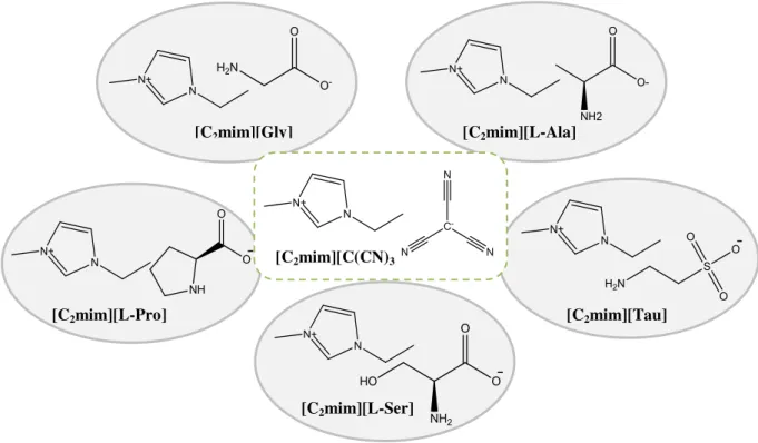
common imidazolium cation ([C2mim]+) were considered. The [C(CN)3]- anion was selected
since it has a extraordinarily low viscosity as previously referred. On the other hand, glycinate anion ([Gly]-) was chosen because it is the simplest available amino acid. Additionally,
L-alaninate ([L-Ala]-) was selected due to its similar chemical structure compared to glycinate.
L-serinate ([L-Ser]-) was chosen because it not only has a similar chemical structure to glycinate
and L-serinate but also comprise an additional hydroxyl group. In order to evaluate the effects of a cyclic structure and the sulfonic group, both L-prolinate ([L-Pro]-) and taurinate ([Tau]-)
were also selected, respectively. The chemical structures of the ionic liquids studied in this work are present in Figure 1.7.
Figure 1.7 -Chemical structures of ionic liquids used in this work. [C2mim][L-Ser]
[C2mim][Tau] [C2mim][L-Pro]
[C2mim][L-Ala] [C2mim][Gly]
41
1.8
Objectives
The main purpose of this work is to evaluate the performance of IL + IL mixtures as new liquid phases to prepare facilitated supported ionic liquid membranes for flue gas separation (CO2/N2). For this purpose, AAILs were selected, so that CO2 facilitated transport
could be attained, and mixed with [C2mim][C(CN)3], a very low viscous IL. In order to increase
the flexibility in tailoring both the permeability and selectivity of these membranes for flue gas separation (CO2/N2), mixtures of varying concentrations were prepared.
Five ionic liquids based on a common cation ([C2mim]+) and anions such as
tricyanomethane ([C(CN)3]-), glycinate ([Gly]-), L-alaninate ([L-Ala]-), taurinate ([Tau]-),
L-serinate ([L-Ser]-) and L-prolinate ([L-Pro]-) were mixed and SILMs were prepared.
The gas permeation properties (permeability, diffusivity and solubility) of CO2 and N2
were determined using a time-lag apparatus.
43
2
Synthesis and Characterization of AAILs
45
The amino acid-based ionic liquids used in this study, namely 1-ethyl-3-methylimidazolium 2-aminoacetate ([C2mim][Gly]), 1-ethyl-3-methylimidazolium
(S)-2-aminopropanoate ([C2mim][L-Ala]), 1-ethyl-3-methylimidazolium 2-aminoethanesulfonate
([C2mim][Tau]), 1-ethyl-3-methylimidazolium (S)-2-amino-3-hydroxypropanoate ([C2
mim][L-Ser]) and 1-Ethyl-3-methylimidazolium (S)-pyrrolidine-2-carboxylate ([C2mim][L-Pro]), were
synthesized via a two-step anion exchange reaction and were characterized by 1H and 13C NMR.
The thermogravimetric analysis (TGA) of the pure ionic liquids and their mixtures was also performed in order to establish the degradation temperature of these liquid phases and thus their upper working temperature limit. This step was especially important in this work since high temperatures are necessary to overcome the energy barrier required for the active gas transport complex formation.
2.1
Materials and Synthesis of AAILs
2.1.1
Materials
Glycine (≥ 98.5 %), L-alanine (≥ 99.5 %), taurine (≥ 99 %), L-serine (≥ 99.5 %) and L
-proline (≥ 99 %), acetonitrile (99.8 %) and methanol (99.8 %) were provided by Sigma Aldrich.
The 1-ethyl-3-methylimidazolium tricyanomethane ([C2mim][C(CN)3]), > 98 wt% pure, and the
1-ethyl-3-methylimidazolium chloride [C2mim][Cl], > 98 wt% pure, were supplied by IoLiTec
GmbH.
2.1.2
Synthesis of amino acid ionic liquids (AAILs)
The ionic liquids used in this study were synthesized via a two-step anion exchange reaction, following an established procedure developed by Ohno et al.61 First, an aqueous solution of 1-ethyl-3-methylimidazolium hydroxide ([C2mim][OH]) was prepared by passing an
aqueous solution of [C2mim][Cl] through a column filled with anion exchange resin (SUPELCO
AMBERLITE IRN-78) (Figure 2.1) in the hydroxide form. Afterwards, the [C2mim][OH] was
neutralized by the dropwise addition of a slight excess of the corresponding equimolar amino acid aqueous solution with cooling. The mixtures were stirred at ambient temperature and pressure for 12 h. Excess of water was then removed by rotary evaporation under reduced pressure. A mixture of acetonitrile and methanol (9:1 v/v) was added to precipitate the unreacted amino acid. After filtration, the solvents were removed by rotary evaporation and the obtained crude products were dried under vacuum (10-3 kPa) and subjected to vigorous stirring
46
contents of the pure ILs and their mixtures were determined by Karl Fischer titration (831 KF Coulometer, Metrohm).
Figure 2.1 - AAILs synthesis method.
Figure 2.2 shows the neat imidazolium-based AAILs at room temperature after the drying procedure. Their purities were confirmed by 1H and 13C NMR analysis (see Appendix 1
for further details).
47
2.2
Thermogravimetric Analysis (TGA)
The onset and decomposition temperatures of the pure ionic liquids and the prepared ionic liquid mixtures with 0.5 of molar fraction were measured using a thermal gravimetric analyzer (TA instrument Model TGA Q50). The samples were placed inside aluminium pans and heated up to 500 °C at a heating rate of 10 °C∙min-1 until complete thermal degradation was achieved.
All samples were recorded under a nitrogen atmosphere. Universal Analysis, version 4.4A software, was used to determine the onset and the decomposition temperatures, as the temperatures at which the baseline slope changes 5% during the heating, and at which the point of greatest rate of change on the weight loss curve (first derivative peak) is observed, respectively.
Considering that temperature is also a crucial parameter on the performance of the prepared SILMs, it was necessary to determine the degradation temperature of the pure ILs and their mixtures considered in the gas transport measurements (Chapter 4).
The obtained onset, T5% and decomposition,Tdeg 1 and Tdeg 2, temperatures are presented
in Table 2.1. Two different decomposition temperatures were considered since two different peaks were obtained in the first derivative weight loss curve, for the five IL mixtures studied.
From Table 2.1, it can be observed that the decomposition temperature for all samples with the exception of the pure [C2mim][C(CN)3] is near to 500 K.
48
Table 2.1 – Onset (T5%) and decomposition (Tdeg 1 and Tdeg 2) temperatures of the pure ILs and their
mixtures.
The two decomposition temperatures obtained, through the first derivative weight loss curve, are illustrated in Figure 2.7, as an example, for the [C2mim][C(CN)3]0.5[L-Ala]0.5 mixture.
Additionally, Figures 2.4, 2.5, 2.8 and 2.9 present the TGA thermogram and derivative weight loss curve, respectively, of the pure [C2mim][C(CN)3] and [C2mim][L-Ala], as
examples. Comparing these results with those of pure ILs it can be concluded that the first decomposition temperature, Tdeg 1, belongs to the AA anion while the second decomposition
temperature, Tdeg 2, is related to [C(CN)3]- anion. The remaining TGA thermograms and
derivative weight loss curves are displayed in Figures 7.11-7.26 (Appendix 2).
From Figure 2.4, it can also be observed that the pure [C2mim][C(CN)3] did not achieve
entirely degradation until ⋍873 K, which means that higher temperatures would be required for its complete degradation. This is entirely in agreement to what has been observed in the literature for ILs containing the [C(CN)3]- anion,77 Furthermore, the decomposition temperatures
of the pure amino acid-based ILs can be ordered as: [C2mim][Gly] < [C2mim][L-Ala] <
[C2mim][L-Ser] < [C2mim][L-Pro] < [C2mim][Tau].
Ionic Liquids T5% (K) Tdeg 1 (K) Tdeg 2 (K)
[C2mim][C(CN)3] 606 634 —
[C2mim][C(CN)3]0.5 [Gly]0.5 484 518 624 [C2mim][C(CN)3]0.5 [L-Ala]0.5 484 512 628 [C2mim][C(CN)3]0.5 [Tau]0.5 530 540 597 [C2mim][C(CN)3]0.5 [L-Ser]0.5 488 524 631 [C2mim][C(CN)3]0.5 [L-Pro]0.5 476 517 551
[C2mim][Gly] 430 500 —
[C2mim][L-Ala] 455 509 —
[C2mim][Tau] 500 574 —
[C2mim][L-Ser] 476 514 —
49
Figure 2.4 - TGA thermogram of the pure [C2mim][C(CN)3].
50
Figure 2.6 – TGA thermogram of [C2mim][C(CN)3]0.5[L-Ala]0.5 mixture.
Figure 2.7- Derivative weight (%/min) of [C2mim][C(CN)3]0.5[L-Ala]0.5 mixture as a function of


![Figure 3.20 - Viscosity deviations of the ionic liquid mixtures at 318.15 K: C 2 mim][C(CN) 3 ][Gly] (□), [C 2 mim][C(CN) 3 ][L-Ala] (▲), [C 2 mim][C(CN) 3 ][Tau] (○), [C 2 mim][C(CN) 3 ][L-Ser] (●), [C 2 mim][C(CN) 3 ][L-Pro] (■)](https://thumb-eu.123doks.com/thumbv2/123dok_br/16480096.732377/77.892.181.725.384.718/figure-viscosity-deviations-ionic-liquid-mixtures-gly-ala.webp)


