biomicrofluidics applications
B. N. Muñoz-Sánchez, S. F. Silva, D. Pinho, E. J. Vega, , and R. Lima
Citation: Biomicrofluidics 10, 014122 (2016); doi: 10.1063/1.4943007
View online: http://dx.doi.org/10.1063/1.4943007
View Table of Contents: http://aip.scitation.org/toc/bmf/10/1
Generation of micro-sized PDMS particles by a flow
focusing technique for biomicrofluidics applications
B. N.Mu~noz-Sanchez,1S. F.Silva,2D.Pinho,2,3E. J.Vega,4,a)
and R.Lima3,5 1
Depto. de Mecanica de Fluidos e Ingenier ıa Aeroespacial, Universidad de Sevilla, E-41092 Sevilla, Spain
2
Polytechnic Institute of Braganc¸a, Campus de Santa Apolonia, Braganc¸a, Portugal
3
CEFT, FEUP, R. Dr. Roberto Frias, 4200-465 Porto, Portugal
4
Depto. de Ingenierıa Mecanica, Energ etica y de los Materiales and Instituto de Computacion Cient ıfica Avanzada (ICCAEx), Universidad de Extremadura, E-06006 Badajoz, Spain
5
MEtRiCS, Mechanical Engineering Department, University of Minho, Campus de Azurem,
4800-058 Guimaraes, Portugal~
(Received 12 January 2016; accepted 17 February 2016; published online 25 February 2016)
Polydimethylsiloxane (PDMS), due to its remarkable properties, is one of the most widely used polymers in many industrial and medical applications. In this work, a technique based on a flow focusing technique is used to produce PDMS spherical particles with sizes of a few microns. PDMS precursor is injected through a hypodermic needle to form a film/reservoir over the needle’s outer surface. This film flows towards the needle tip until a liquid ligament is steadily ejected thanks to the action of a coflowing viscous liquid stream. The outcome is a capillary jet which breaks up into PDMS precursor droplets due to the growth of capillary waves producing a micrometer emulsion. The PDMS liquid droplets in the solution are thermally cured into solid microparticles. The size distribution of the particles is analyzed before and after curing, showing an acceptable degree of monodispersity. The PDMS liquid droplets suffer shrinkage while curing. These microparticles can be used in very varied technological fields, such as biomedicine, biotechnology, pharmacy, and industrial engineering.VC 2016 AIP Publishing LLC.
[http://dx.doi.org/10.1063/1.4943007]
I. INTRODUCTION
Polydimethylsiloxane (PDMS) is a useful polymer in many industrial and medical applications due to its remarkable properties, such as good optical transparency, flexibility, non-toxicity, chemical inertness, thermal stability, biocompatibility, and permeability to gases.1,2It is widely used to fabri-cate microfluidic devices to perform blood cells separation3–6and deformability analysis,7,8to culture endothelial cells,9–11and to investigate several flow phenomena happening in microvessels.12–14
In the last years, the production of monodisperse particles with this inert elastomer has stimulated great interest of researchers because of their potential applications, especially in biomedicine.15 Microfluidics, particularly flow focusing principle, has proven to be an extra-ordinary working platform to produce fluid microentities. A co-flowing method was used to generate amphiphilic PDMS particles with hundreds of microns in size by Zhaoet al.16 Jiang
et al.15 have proposed a flow-focusing technique where a PDMS precursor was dispersed into microdroplets within an aqueous continuous phase. By using this method, they were able to produce PDMS microbeads with an average dimension of 80lm to use them as discrete
oxy-gen sensors. However, in many applications it is essential to have PDMS microparticles with
a)
Author to whom correspondence should be addressed. Electronic mail: [email protected]. Tel.:þ34-924-289600. Fax: þ34-924-289601.
dimensions below 10lm. For example, to develop blood analogue fluids, PDMS
micropar-ticles must have dimensions closer to the red blood cells (RBCs), which are the most abun-dant cells in blood, with a contribution of around 45% by volume.14
The study of the blood flow behaviour through microchannels is crucial to improve our understanding about phenomena happening in the human microcirculatory system. However, the difficulties associated with the use of in vitro blood, such as coagulation and sample stor-age, have promoted the increasing interest to develop fluids with rheological properties similar to real blood.17 The most typical blood analogues used in experimental flow studies are either Newtonian using a mixture of glycerine and water or non-Newtonian aqueous solutions based on xanthan gum and polyacrylamide.17–19 However, blood analogue solutions taking into account only the rheological behaviour is not enough to ensure an accurate representation of several blood physiological phenomena happening in microcirculation. For this reason, the de-velopment of more reliable blood analogues is of great importance and still lacking. Ideally, particulate solutions having particles that mimic key structural attributes of RBCs including size, shape, and mechanical properties would be an excellent candidate to reproduce multiphase effects of blood. A very recent study, rigid polymethylmethacrylate microparticles were sus-pended in Newtonian and non-Newtonian solutions to mimic both rheological properties of blood and the cell free layer (CFL) that frequently happens in microcirculation.20 However, by using rigid microparticles the CFL was only formed downstream of a hyperbolic contraction, whereas no CFL was observed at the upstream region. Hence, this work shows evidence for the need to develop flexible microparticles such as the PDMS microparticles generated by the flow focusing technique reported here.
The flow focusing technique is very attractive because it uses purely hydrodynamic means to produce monodisperse collections of micrometer drops at a continuous high rate.21,22 In flow focusing,21an outer coflowing stream accelerates and steadily ejects a liquid injected through a feeding capillary. Both the liquid jet and the outer stream cross an orifice located in front of the capillary and whose diameter is much larger than that of the microjet. If the outer stream is a high-speed gas current,21 the outcome is a capillary jet which breaks up into droplets due to the Rayleigh instability.23 When the focusing effect is caused by a viscous liquid current, emulsions consisting of micrometer droplets are produced.22 In this case, both the inner and outer liquids coflow downstream with almost the same speed until the interface pinches due to the growth of capillary waves too. Drops significantly larger than those predicted by the inviscid Rayleigh’s theory23 can be obtained due to the disparity between the two viscosities involved.24
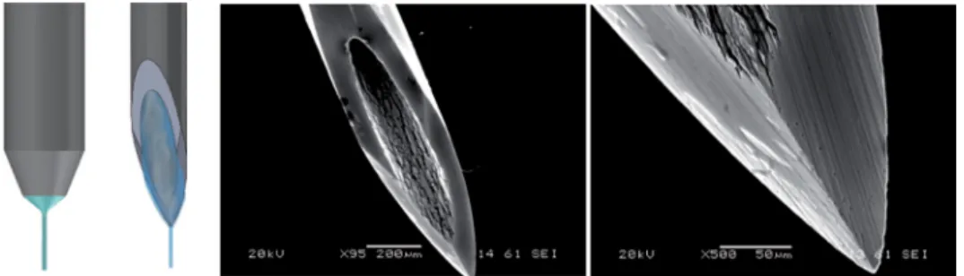
A new flow focusing technique25 has recently been proposed for producing jets, droplets, and emulsions with sizes ranging from tens of microns down to the submicrometer scale. The cylindrical capillary used in the classical flow focusing.21,22,26,27 is replaced with a (common) hypodermic needle of a similar dimension (see Fig. 1). The needle ends in a sharp tip over which the injected liquid flows dragged by the outer current. In this way, the tapering meniscus of the standard flow focusing configuration is substituted by a Couette-type flow directed towards the needle tip. A liquid ligament is ejected from the very tip of the needle, which is
only a few microns in size. This constitutes a fundamental change in the flow focusing method because it alters completely the dynamics and, therefore, the stability of the liquid source.
In this work, a technique based on that proposed by Acero et al.25 is used to produce PDMS microparticles below 10lm. It must be pointed out that such small particles are
pro-duced with orifices of about 200lm in diameter, thereby avoiding the clogging of the
injec-tion system. Addiinjec-tionally, our technique is able to produce particles with an acceptable monodispersity.
The paper is organized as follows. The materials and experimental technique used in this work is presented in Sec. II. This includes describing the considered experimental apparatus and working fluids (Sec.II A), and the experimental procedure (Sec.II B). In Sec. III, we pres-ent the results of the generated primary and satellite droplets diameter followed by solid par-ticles diameter after curing. The paper closes with the main conclusions in Sec.IV.
II. EXPERIMENTAL METHOD
A. Experimental apparatus
The experimental setup is sketched in Fig. 2. We used a hypodermic needle (Becton
Dickinson Microlance 3 30G 1/2) with an inner (outer) diameter of about 160 (300)lm, and
with an outer hydraulic radiusrtof a few microns in the tip (around 3lm). The needle tip was
not subjected to any kind of treatment. The needle was placed inside a glass cylindrical capil-lary (A), with 200lm in diameter and 1 cm in length, by using high-precision
orientation-trans-lation systems (B). We used a common PDMS elastomer kit (Dow Corning Sylgard 186 Silicone Elastomer Kit) consisting of two parts: a base of vinyl-terminated siloxane oligomers (Part A) and a curing agent of siloxane oligomers and catalyst (Part B). The proportion Part A:Part B of the mixture was 6:4, whose viscosity was around 827 cSt,15 in order to decrease the viscosity of the PDMS precursor making its focusing easier. The mixture was injected through the needle at a constant flow rate, e.g., 0.1 ml/h, by means of a syringe pump connected to a stepping motor. Thanks to it, a film/reservoir was formed around the tip of the needle before starting production and was fed to maintain the ejection during the production. The nee-dle and the glass cylindrical capillary were immersed in a bath of a mixture (9:1) of glycerol qp (Panreac) and surfactant Brij[textregistered] L4 (Sigma-Aldrich) to avoid the coalescence of the droplets downstream. This solution is immiscible with the PDMS precursor. The outer bath was suctioned across the glass cylindrical capillary at a constant flow rate Q¼2 ml/h with another syringe pump to produce the focusing effect. Both mixtures were prepared carefully by agitation at very low speeds, by using a magnetic stirrer (Agimatic-E, P-Selecta) in the case of the glycerol and surfactant mixture. Experiments were conducted at 2462C.
Digital images of the fluid configuration were acquired using an ultra-high-speed CMOS camera (Photron, Fastcam SA5) (C) which allowed us to take images with an exposure time from 50ls down to 340 ns. The camera was equipped with a set of optical lenses (D). The
opti-cal lenses were selected depending on the size of the imaged object, with a magnification rang-ing from 0.076 to 0.52lm/pixel. This parameter was calculated for each optical system by
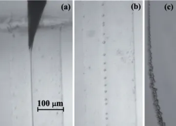
measuring the diameter of a calibration rod located in the field of view. In this way, the optical distortion caused by the glass capillary was checked to be negligible. The camera could be dis-placed both horizontally and vertically using a triaxial translation stage (E) to focus the jet. The fluid configuration was illuminated from the back side with the cool white light provided by an optical fiber light source (F). We also acquired images of the needle by using an auxiliary CCD camera (not shown in Fig. 2) assembled in an optical axis perpendicular to that of the CMOS camera. The use of the two cameras allowed us to check that the needle was correctly posi-tioned. All these elements were mounted on an optical table (G) with a pneumatic anti-vibration isolation system (H) to damp the anti-vibrations coming from the building. By way of illustration, Fig. 3 shows three images acquired in the course of the experiments along the stream of fluids: (a) emitted jet of PDMS precursor attached to the needle tip, (b) PDMS drop-lets about 7lm in diameter formed after the jet breakage travelling through the glass cylindrical
capillary, and (c) stream of these droplets downstream the glass capillary.
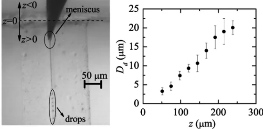
The production of the liquid microjet entails the stretching of a tiny meniscus hanging on the needle tip (see image of Fig.5). That stretching takes place due to the combination of both extensional viscous stresses associated with the outer flow acceleration and the drag force due to the difference between the continuous and disperse phase velocities. In this sense, the phe-nomenon should be regarded as flow focusing rather than as a co-flow of two liquid streams.28 As it will be shown in Fig. 5, the fact that the jet diameter depends significantly on the needle tip position in the glass cylindrical capillary confirms that the focusing effect is relevant in the present phenomenon.
B. Experimental procedure
The size of the liquid droplets and solid particles (just after curing) was measured system-atically by processing the images to determine their dependence on the control parameters of the problem. So we could compare the results before and after curing for the production of sev-eral samples of different droplet sizes.
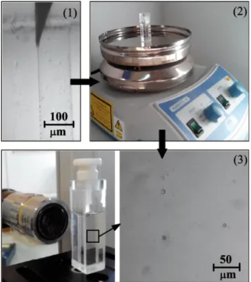
Figure4gives a general outline of the steps followed in each experimental realization, con-sisting of:
(1) The experimental configuration described above was used to produce liquid droplets of PDMS precursor by purely hydrodynamic means. A film is formed on the outer surface of a hypoder-mic needle by injecting PDMS precursor at a constant flow rate. The coflowing fluid stream drags the film to the very tip of the needle and provides it with the momentum necessary to overcome the surface tension forming a small jet. The proposed method benefits from the re-markable stability of the fluidic structure from which the jets originate.25During the produc-tion time (around 2 h), images were recorded to measure the size distribuproduc-tion of the droplets. (2) When the production system was halted, the emulsion obtained (around 4 ml) was deposited in a
glass optical cell. This container was heated up at 70C for 14 h by using the heater of a common magnetic stirrer in order to conduct crosslinking and cure the PDMS droplets in the solution. (3) Then, when the solution cooled down to the room temperature, the PDMS solid particles were
visualized to measure the size distribution of the particles after curing by using our optical imaging method. The optical cell was scanned carefully to find, focus, and measure the size of the solidified particles of PDMS within the glycerol-surfactant bath.
It must be noted that the film of PDMS precursor around the needle was much larger than the size of the jet eventually ejected from the needle tip, and it was growing very slowly during our experiments. It means that this film worked as a reservoir from which the system suctioned the flow rate necessary to form a stable jet, depending on the position of the needle tip inside the cylindrical glass capillary and the dragging flow rateQ. Therefore, for a fixedQ, the system established a natural flow rate for each position of the needle, which was the real flow rate of the jet emitted. This natural flow rate Qn can be estimated from the videos/images of our
experiments recorded at 28 000 frames/s with an exposure time of 35ls, just by counting the
number of primary spherical droplets produced over time and multiplying this value by the mean volume of the primary droplet.
III. RESULTS
During the experiments, we checked that the present technique is very sensitive to the posi-tion (in the three direcposi-tions of space) of the needle tip in the glass capillary. In fact, when one fixes it in the center of the orifice, the size of droplets produced can be precisely controlled by shifting the needle tip along the axis of the cylindrical glass capillary without varying the flow rates. Figure5shows the diameterDdof the liquid droplets plotted as a function of the distance zbetween the needle tip and the entrance to the capillary. Dd increases as zgrows, i.e., as the
needle is moved downstream inside the glass capillary. Eventually the jet is destabilized and breaks up into droplets.29 It was verified that the jet’s breakage gave rise to a quasi-monodisperse collection of primary drops whose diameterDdwas roughly twice the jet’s
diam-eterDj. It must be noted that Rayleigh’s dispersion relation does not apply to our experimental
configuration due to the high viscosities of both the inner and outer streams, but using Tomotika’s dispersion relation for the Stokes regime,24 one gets Dd’2:01Dj, which
approxi-mately coincides with our experimental results.
The PDMS precursor jet breakup results in the formation of primary and satellite droplets (see Fig. 6, right). The size and formation of satellite droplets are directly linked with the dynamic of the rupture of the neck (between two primary drops). In the linear regime, the thread cross-section of maximum liquid depletion is that equidistant between the two primary
FIG. 5. DiameterDdof the produced droplets by focusing PDMS precursor with the mixture of glycerol and surfactant Brij
L4 and its dependence onzposition.
FIG. 6. Probability distributionPðDdÞfor the droplet diameterDdproduced with our technique forz¼144lm,Qn’10ll/h,
drops, but that section can shift towards the vicinities of those drops in the non-linear phase. As a consequence, a liquid ligament forms and inflates between the primary drops, which gen-erates a satellite droplet. It is well-known that the formation of satellite drops for non-viscous liquids is driven by inertia.30 Due to the high viscosity of the liquids involved in the present technique, the Stokes regime was reached in our experiments, and so inertia can be neglected. In this viscous case, a highly nonlinear phenomenon produces the appearance of those satellite droplets,31nonlinearity comes from the surface tension force.
The size of the satellite drops depends on the viscosity ratio between continuous and dis-persed phases.32 For each experimental run, we observed the formation of satellite droplets to be almost constant in size. In all the cases, the satellite droplet size ranged from around 4lm
in diameter down to values hardly observable with standard microscopy. The formation and size of the satellite droplets in our configuration could be quantitatively influenced by the use of surfactant in the outer stream. The presence of surfactants can greatly dampen and suppress surface waves. Zhang and Basaran33found that the volume of satellite drops grew with increas-ing surfactant concentration. The accumulation of surfactants on the drop surface helps to stabi-lize the rapidly stretching thread during drop breakup and thereby increases the volume of the liquid thread and ultimately that of the satellite. On the other hand, the complex chemical com-position of PDMS precursor could lead to a rheological behavior on the jet breakup participat-ing in the production of such satellite droplets too. Figure6 shows the probability distribution PðDdÞ obtained for both primary and satellite droplets produced for z¼144lm, Qn’10ll/h,
andQ¼2 ml/h. The average diameterDd was determined to be 10.79 (2.94)lm and the standard
deviation r was 1.47 (0.77)lm for primary (satellite) droplets. The coefficient of variance Cv, Cv¼ r
Dd100, for primary and satellite drops was 13.6% and 26.19%, respectively. As can be observed, these two collections of drops exhibit a relatively high degree of monodispersity. The number of satellite drops represented around 50% of the complete sample. The polydispersity can be partially explained by the observed fluctuations of the wavelength responsible for the jet pinch-off.
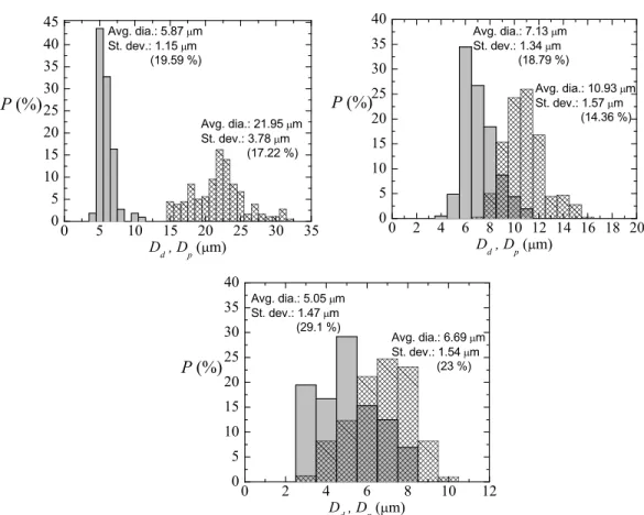
In order to characterize appropriately the technique here depicted, experiments were con-ducted to measure the size of liquid primary droplets and subsequent solid particles (just after curing) for several cases. For this purpose, the emulsion obtained was heated up to cure the PDMS droplets, and the subsequent PDMS solid particles were afterwards visualized by scan-ning the optical glass cell contaiscan-ning the solution with optical microscopy. Figure 7shows the probability distribution PðDdÞ for the primary liquid droplet diameter Dd and PðDpÞ for the
solid particle diameter after curing Dp, for three samples with different size of the primary
droplets. In all the cases, before and after curing, the coefficient of variance Cvis around 20%,
and it can be considered as a relatively high degree of monodispersity, taking into account the smallness of the samples of droplets/particles. Interestingly, it was always found a pronounced shrinkage of the liquid droplets after turning into solid particles, that is,Dp<Dd.
PDMS shrinkage is highly variable as many parameters are involved, especially when working in a multi-user environment without tightly controlled fabrication conditions.34 Typically, it is characterized on a case-by-case basis and individual calibration or alignment methods are needed for each design. For further analysis of the shrinkage produced by curing
in our experiments, we calculated a curing shrinkage coefficientCs asCs¼DdDDp
d 100. Figure8 depicts the values for the samples in Fig. 7, for liquid droplet diameters approximately com-prised between 5 and 25lm, the range of diameters the present technique is designed for. Cs
increased considerably with the average liquid droplet diameter Dd, and interestingly, linear
dependency of Cswith respect toDd can be found within that relatively small range. The
equa-tion Cs’103 Dd could predict approximately this shrinkage. For much higher droplet diameters,
surface effects can be neglected, and one expects the shrinkage of the droplet to be proportional to its volume, i.e., Dp’aDd (a<1). In this case, Csbecomes a constant. This behavior is not
each sample have different density. To the best of the authors’ knowledge, it is the first time that such shrinkage is reported for PDMS spherical microparticles. Lee and Lee35 observed PDMS shrinkage to increase with growing curing temperature, layer thickness and width, and mixing ratio of dilutant and curing agent, for theirs 2D PDMS structure. Jeong and Konishi36
FIG. 7. Probability distributionPðDdÞfor the primary liquid droplet diameterDd(meshed bars) andPðDpÞfor the solid
parti-cle diameter after curingDp(gray bars). The parameters characterizing the production were (a)z¼240lm,Qn’50ll/h, and Q¼2 ml/h; (b)z¼144lm,Qn’10ll/h, andQ¼2 ml/h; (c)z¼90lm,Qn’1ll/h, andQ¼2 ml/h. Note that the results of
(b) came from a different experimental realization from that of Fig.6, for the same parameters characterizing the production. It shows that the results are reproducible for primary liquid droplets.
FIG. 8. Curing shrinkage coefficientCsof the PDMS liquid droplets after curing as a function of the original diameter in
found PDMS molds/stamps shrinkage to be size-dependent, being greater for increasing dimen-sions, as occurred in our experiments. They also showed the temperature-dependence. Shrinkage is also dependent on the ambient during curing, different shrinkage velocities were found when the PDMS surface was exposed to air or not.37 In our experiments, the unusually high amount of curing agent could have pronounced the shrinkage of the samples.
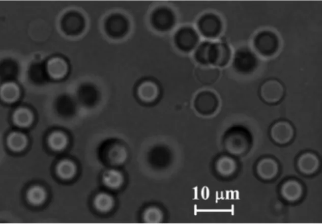
The PDMS microparticles produced by our technique can be either stored in the glycerol and surfactant solution or centrifuged, rinsed, and dried under vacuum to a powder. Dried particles can be re-dispersed in various media depending on the application (see Fig. 9). To investigate whether the produced cured PDMS microparticles have flow properties similar to
in vitro experiments,2,4–8,12–14 rheological measurements were performed for a fluid containing cured PDMS particles and Dextran 40 (Dx40). The sample containing cured PDMS micropar-ticles, with an average diameter of 5.87lm, was dried and suspended in Dx40. Moreover,
rheo-logical measurements were also performed for two additional working fluids, i.e., a solution containing only Dx40 and another containing ovine RBCs suspended in Dx40 at 5% by volume. More detailed information regarding the preparation of the in vitroblood sample can be found at Ref.38. The rheological characterization of the working fluids was carried out by means of a stress controlled rheometer (Bohlin CVO, Malvern, Worcestershire, UK) using a cone-plate ge-ometry with 55 mm of diameter and an angle of 1, where all measurements were carried out at 20C. The flow behavior of the samples under steady state experiments is shown in Fig. 10. Two tendencies in their viscosity curves are clearly distinguished. On one hand, the sample containing only Dx40 presents a clear Newtonian flow behavior, with a constant viscosity. On
FIG. 9. Image, obtained by using an inverted microscope, of the cured PDMS particles (corresponding to the sample of Fig.7(b)) re-dispersed in Dextran 40.
the other hand, both samples containing cured PDMS microparticles and ovine RBCs, at low shear rates present a smooth shear thinning behavior and a constant viscosity at high shear rates. It is also clear from these results that the sample containing PDMS microparticles shows a good agreement with the rheological properties of thein vitroblood sample.
IV. CONCLUSIONS
In this work, we have applied a flow focusing technique to produce PDMS microparticles with diameters below 10lm, and relatively high degree of monodispersity. One of the features
of the present technique is that the variation of the needle position in the glass capillary enables one to select the size of the resulting PDMS precursor droplets, which confers both flexibility and robustness on the method. It was found a shrinkage of these droplets while curing.
The degree of monodispersity could be improved by controlling precisely the wavelength of the breakage of the jet, e.g., by using a piezoelectric mechanism. The ability to control the size and other mechanical properties of such microparticles will enable the production of inno-vative and versatile delivery vehicles suitable for different biomedical applications. For instance, the proposed microparticles have great potential to mimic the structural and functional properties of blood cells and consequently to develop a blood analogue fluid with rheological properties similar to real blood.
ACKNOWLEDGMENTS
The authors acknowledge the financial support provided by Fundac¸~ao para a Ci^encia e a Tecnologia (FCT), COMPETE and FEDER through the Projects PTDC/SAU-ENB/116929/2010, EXPL/EMS-SIS/2215/2013, PTDC/QEQ-FTT/4287/2014 and fellowship SFRH/BD/89077/2012. Partial support from the spanish Ministry of Science and Education (Grant No. DPI2013-46485), Junta de Extremadura (Grant No. GR10047), and “la Caixa” Foundation (predoctoral grant) is gratefully acknowledged too. Finally, we thank Jose M. Montanero for his helpful suggestions and discussion on the results.
1A. Mata, A. Fleischman, and S. Roy, “Characterization of polydimethylsiloxane (PDMS) properties for biomedical
micro/nanosystems,”Biomed. Microdevices7, 281–293 (2005).
2R. Lima, S. Wada, S. Tanaka, M. Takeda, T. Ishikawa, K. Tsubota, Y. Imai, and T. Yamaguchi, “In vitroblood flow in a
rectangular PDMS microchannel: Experimental observations using a confocal micro-piv system,”Biomed. Microdevices
10, 153–167 (2008). 3
H. W. Hou, A. A. Bhagat, A. G. Chong, P. Mao, K. S. Tan, J. Han, and C. T. Lim, “Deformability based cell margina-tion—a simple microfluidic design for malaria-infected erythrocyte separation,”Lab Chip10, 2605–2613 (2010). 4T. Tanaka, T. Ishikawa, K. Numayama-Tsuruta, Y. Imai, H. Ueno, N. Matsuki, and T. Yamaguchi, “Separation of cancer
cells from a red blood cell suspension using inertial force,”Lab Chip12, 4336–4343 (2012).
5D. Pinho, T. Yaginuma, and R. Lima, “A microfluidic device for partial cell separation and deformability assessment,”
BioChip J.7, 367–374 (2013).
6R. O. Rodrigues, D. Pinho, V. Faustino, and R. Lima, “A simple microfluidic device for the deformability assessment of
blood cells in a continuous flow,”Biomed. Microdevices17, 108 (2015).
7T. Yaginuma, M. S. N. Oliveira, R. Lima, T. Ishikawa, and T. Yamaguchi, “Human red blood cell behaviour under
homo-geneous extensional flow in a hyperbolic-shaped microchannel,”Biomicrofluidics7, 054110 (2013).
8V. Faustino, D. Pinho, T. Yaginuma, R. Calhelha, I. Ferreira, and R. Lima, “Extensional flow-based microfluidic device:
Deformability assessment of red blood cells in contact with tumor cells,”BioChip J.8, 42–47 (2014). 9
M. Shin, K. Matsuda, O. Ishii, H. Terai, M. Kaazempur-Mofrad, J. Borenstein, M. Detmar, and J. P. Vacanti, “Endothelialized networks with a vascular geometry in microfabricated poly(dimethyl siloxane),”Biomed. Microdevices
6, 269–278 (2004).
10T. Ohashi and M. Sato, “Endothelial cell responses to fluid shear stress: From methodology to applications,” inSingle
and Two-phase Flows on Chemical and Biomedical Engineering(Bentham Science Publishers, 2012), pp. 579–599. 11D. Huh, Y. S. Torisawa, G. A. Hamilton, H. J. Kim, and D. E. Ingber, “Microengineered physiological biomimicry:
Organs-on-chips,”Lab Chip12, 2156–2164 (2012). 12
M. Abkarian, M. Faivre, R. Horton, K. Smistrup, C. A. Best-Popescu, and H. A. Stone, “Cellular-scale hydrodynamics,” Biomed. Mater.3, 034011 (2008).
13
V. Leble, R. Lima, R. Dias, C. Fernandes, T. Ishikawa, Y. Imai, and T. Yamaguchi, “Asymmetry of red blood cell motions in a microchannel with diverging and converging bifurcation,”Biomicrofluidics5, 044120 (2011).
14
R. Lima, T. Ishikawa, Y. Imai, and T. Yamaguchi, “Blood flow behavior in microchannels: Past, current and future trends,” inSingle and Two-phase Flows on Chemical and Biomedical Engineering(Bentham Science Publishers, 2012), pp. 513–547.
15K. Jiang, P. C. Thomas, S. P. Forry, D. L. DeVoe, and S. R. Raghavan, “Microfluidic synthesis of monodisperse PDMS
16
L.-B. Zhao, S.-Z. Li, H. Hu, Z.-X. Guo, F. Guo, N.-G. Zhang, X.-H. Ji, W. Liu, K. Liu, S.-S. Guo, and X.-Z. Zhao, “A novel method for generation of amphiphilic PDMS particles by selective modification,” Microfluid. Nanofluid.10, 453–458 (2011).
17P. C. Sousa, F. T. Pinho, M. S. N. Oliveira, and M. A. Alves, “Extensional flow of blood analog solutions in microfluidic
devices,”Biomicrofluidics5, 014108 (2011). 18
A. D. Anastasioua, A. S. Spyrogiannia, K. C. Koskinasb, G. D. Giannogloub, and S. V. Parasa, “Experimental investiga-tion of the flow of a blood analogue fluid in a replica of a bifurcated small artery,”Med. Eng. Phys.34, 211–218 (2012). 19
L. Campo-Dea~no, R. P. A. Dullens, D. G. A. L. Aarts, F. T. Pinho, and M. S. N. Oliveira, “Viscoelasticity of blood and viscoelastic blood analogues for use in polydimethylsiloxanein vitromodels of the circulatory system,”Biomicrofluidics
7, 034102 (2013). 20
J. Calejo, D. Pinho, F. J. Galindo-Rosales, R. Lima, and L. Campo-Dea~no, “Particulate blood analogues reproducing the erythrocytes cell free layer in a microfluidic device containing a hyperbolic contraction,”Micromachines7, 4 (2016). 21
A. M. Ga~nan-Calvo, “Generation of steady liquid microthreads and micron-sized monodisperse sprays in gas streams,” Phys. Rev. Lett.80, 285–288 (1998).
22
A. M. Ga~nan-Calvo and P. Riesco-Chueca, “Jetting-dripping transition of a liquid jet in a lower viscosity co-flowing immiscible liquid: The minimum flow rate in flow focusing,”J. Fluid Mech.553, 75–84 (2006).
23
L. Rayleigh, “On the instability of jets,”Proc. London Math. Soc.s1–10, 4–13 (1878). 24
S. Tomotika, “On the instability of a cylindrical thread of a viscous liquid surrounded by another viscous fluid,”Proc. R. Soc. London150, 322–337 (1935).
25
A. J. Acero, N. Rebollo-Mu~noz, J. M. Montanero, A. M. Ga~nan-Calvo, and E. J. Vega, “A new flow focusing technique to produce very thin jets,”J. Micromech. Microeng.23, 065009 (2013).
26
M. A. Herrada, A. M. Ga~nan-Calvo, A. Ojeda-Monge, B. Bluth, and P. Riesco-Chueca, “Liquid flow focused by a gas: Jetting, dripping, and recirculation,”Phys. Rev. E78, 036323 (2008).
27
J. M. Montanero, N. Rebollo-Mu~noz, M. A. Herrada, and A. M. Ga~nan-Calvo, “Global stability of the focusing effect of fluid jet flows,”Phys. Rev. E83, 036309 (2011).
28A. M. Ga
~
nan-Calvo, J. M. Montanero, L. Martın-Banderas, and M. Flores-Mosquera, “Building functional materials for health care and pharmacy from microfluidic principles and flow focusing,”Adv. Drug Delivery Rev.65, 1447–1469 (2013).
29
S. Tomotika, “Breaking up of a drop of viscous liquid immersed in another viscous fluid which is extending at a uniform rate,”Proc. R. Soc. London153, 302–318 (1936).
30
J. Eggers, “Universal pinching of 3D axisymmetric free-surface flow,”Phys. Rev. Lett.71, 3458–3460 (1993). 31
M. Tjahjadi, H. A. Stone, and J. M. Ottino, “Satellite and subsatellite formation in capillary breakup,”J. Fluid Mech.
243, 297–317 (1992). 32
O. Carrier, E. Dervin, D. Funfschilling, and H.-Z. Li, “Formation of satellite droplets in flow-focusing junctions: Volume and neck rupture,”Microsyst. Technol.21, 499–507 (2015).
33
X. Zhang and O. A. Basaran, “An experimental study of dynamics of drop formation,”Phys. Fluids7, 1184–1203 (1995). 34C. Moraes, Y. Sun, and C. A. Simmons, “Solving the shrinkage-induced PDMS alignment registration issue in multilayer
soft lithography,”J. Micromech. Microeng.19, 065015 (2009).
35S. W. Lee and S. S. Lee, “Shrinkage ratio of PDMS and its alignment method for the wafer level process,”Microsyst. Technol.14, 205–208 (2007).
36
O. C. Jeong and S. Konishi, “Controlling the size of replicable polydimethylsiloxane (PDMS) molds/stamps using a step-wise thermal shrinkage process,”Microelectron. Eng.88, 2286–2289 (2011).
37
J. N. Lee, C. Park, and G. M. Whitesides, “Solvent compatibility of poly(dimethylsiloxane)-based microfluidic devices,” Anal. Chem.75(23), 6544–6554 (2003).
38