A DSL for PIM Specifications: Design and
Attribute Grammar based Implementation
Ivan Luković1, Maria João Varanda Pereira2, Nuno Oliveira3, Daniela da Cruz3, Pedro Rangel Henriques3
1 University of Novi Sad, Faculty of Technical Sciences, Trg D. Obradovića 6, 21000 Novi Sad, Serbia,
2 Polytechnic Institute of Bragança, Escola Superior de Tecnologia e Gestão, Campus de Santa Apolónia - Apartado 1134
5301-857Bragança, Portugal [email protected]
3 Universisty of Minho, Department of Computer Science, Campus de Gualtar - 4710-057 Braga, Portugal
{nunooliveira, danieladacruz, prh}@di.uminho.pt
Abstract. IIS*Case is a model driven software tool that provides information system modeling and prototype generation. It comprises visual and repository based tools for creating various platform independent model (PIM) specifications that are latter transformed into the other, platform specific specifications, and finally to executable programs. Apart from having PIMs stored as repository definitions, we need to have their equivalent representation in the form of a domain specific language. One of the main reasons for this is to allow for checking the formal correctness of PIMs being created. In the paper, we present such a meta-language, named IIS*CDesLang. IIS*CDesLang is specified by an attribute grammar (AG), created under a visual programming environment for AG specifications, named VisualLISA.
Keywords: Information System Modeling; Model-Driven Approaches; Domain Specific Languages; Domain Specific Modeling; Attribute Grammars.
1. Introduction
performed in IIS*Case to obtain executable program code of software applications and database scripts for a selected target platform. One of the main motives for developing IIS*Case is in the following. For many years, the most favorable conceptual data model is widely-used Entity-Relationship (ER) data model. A typical scenario of a database schema design process provided by majority of existing CASE tools is to create an ER database schema first and then transform it into the relational database schema. Such a scenario has many advantages, but also there are serious disadvantages. One of them, presented in [11] is named "lack of semantic" problem. Actually, there are many examples in which the same structure of ER database schema should not be transformed into the same relational database schema structure, due to the different semantics assigned to the ER structure. In other words, the transformation process depends not only on the formal mapping rules, but also on the problem domain semantics. We overcome these disadvantages by creating an alternative approach and related techniques that are mainly based on the usage of model driven software development (MDSD) [3] and Domain Specific Language (DSL) [4, 10] paradigms. The main idea was to provide the necessary PIM meta-level concepts to IS designers, so that they can easily model semantics in an application domain. After that, they may utilize a number of formal methods and complex algorithms to produce database schema specifications and IS executable code, without any expert knowledge.
In order to provide design of various PIM models by IIS*Case, we created a number of modeling, meta-level concepts and formal rules that are used in the design process. Besides, we also developed and embedded into IIS*Case visual and repository based tools that apply such concepts and rules. They assist designers in creating formally valid models and their storing as repository definitions in a guided way.
used to create PIM project specifications that may be latter transformed into the other specifications, and finally to programs.
There are a number of meta-modeling approaches and tools suitable for the purpose of creating IIS*CDesLang. To create IIS*CDesLang, a visual programming environment (VPE) for AG specifications, named VisualLISA [19, 21] is selected. In the paper, we focus on the following application PIM concepts: project, application system, form type, component type, application, call type, and basilar concepts as attribute and domain. We applied VisualLISA Syntactic and Semantic Validators to check the correctness of the specified grammar.
A benefit of introducing IIS*CDesLang is to enable the creation of a parser aimed at checking the formal correctness of project models under development. In this way, we may help designers in raising the quality of new IS specifications. A possibility to build two translators, IIS*Case repository-to-IIS*CDesLang specifications and IIS*CDesLang-to-IIS*Case repository definitions, is another value added by this approach. The benefit of the first one is to allow the correctness checking of PIM visual models without explicitly writing IIS*CDesLang specifications; and the benefit of the second one is a possibility of generating correct PIM repository specifications from IIS*CDesLang textual specifications. Currently, we developed, using VisualLISA, an AG specifications of IIS*CDesLang. Apart from having the AG specification of IIS*CDesLang, we also need the appropriate checkers. They are still under development. Therefore, we were not able so far to test the efficiency of the concept as a whole. It remains to be one of our next research tasks. The main goal of this paper is to present a part of such VisualLISA specification and address main future research directions.
Apart from Introduction and Conclusion, the paper is organized in four sections. In Section 2 we present a related work, while in Section 3 we give a short presentation of IIS*Case. Selected IIS*CDesLang PIM concepts are briefly described in Section 4. In Section 5 we present preliminaries about VisualLISA programming environment and an AG specification of IIS*CDesLang, created by VisualLISA.
2. Related
Work
Domain Specific Languages are tailored to specific application domain and offer to users more appropriate notations and abstractions. Usually DSLs are more expressive and are easier to use than GPLs for the domain in question, with gains in productivity and maintenance costs.
The design of a new DSL is usually made when it is needed to make programming more accessible to end-users, to improve correctness of the written programs, to improve the program developing time and to make maintenance easier.
(MOF) [17] proposed by the OMG, where the meta-model is created by means of UML class diagrams and Object Constraint Language (OCL). The Generic Modeling Environment (GME) [23] is a configurable toolkit for domain-specific modeling and program synthesis. In MetaEdit+ [18] models are created through a graphical editor and a proprietary Report Definition Language is used to create code from models. The Eclipse Modeling framework (EMF) [5] is also a commonly used meta-modeling framework, where meta-meta-model named Ecore is used to create meta-models, or to import them from UML tools or textual notations like one presented in [6].
We may find a considerable number of references presenting the applications of such approaches and tools in various problem domains, as it is, for example, [8]. The same approaches can also be used for the design of IIS*CDesLang, too.
In general, our current research goals are to apply two closely related approaches to formally describe our IIS*Case environment. One of them is based on MOF and the appropriate Domain Specific Modeling (DSM) tools comprising specification language generators. The other one is applied in this paper. It is based on creating textual DSLs by means of the appropriate visually oriented tools with compiler generators. Although there is huge number of references covering many applications of both approaches in various problem domains, unfortunately, we still could not find references communicating ideas how to formally specify a CASE / MDSD tool by means of DSM and DSL approaches.
3. IIS*Case and Conceptual Modeling
IIS*Case, as a software tool assisting in IS design and generating executable application prototypes, currently provides:
Conceptual modeling of database schemas, transaction programs, and business applications of an IS;
Automated design of relational database subschemas in the 3rd normal form (3NF);
Automated integration of subschemas into a unified database schema in the 3NF;
Automated generation of SQL/DDL code for various database management systems (DBMSs);
Conceptual design of common user-interface (UI) models; and
between the specification of a system and its implementation on a particular platform. Therefore, modeling is performed at the high abstraction level, because a designer creates an IS model without specifying any implementation details. Besides, IIS*Case provides some model-to-model transformations from PIM to Platform-Specific Models (PSM) and model-to-code transformations from PSMs to the executable program model-to-code.
Detailed information about IIS*Case may be found in several authors' references and we do not intend to repeat them here. A case study illustrating main features of IIS*Case and the methodological aspects of its usage is given in [12]. The methodological approach to the application of IIS*Case is presented in more details in [14]. At the abstraction level of PIMs, IIS*Case provides conceptual modeling of database schemas that include specifi-cations of various database constraints, such as domain, not null, key and unique constraints, as well as various kinds of inclusion dependencies. Such a model is automatically transformed into a model of relational database schema, which is still technology independent specification. It is an example of model-to-model transformations provided by IIS*Case [13].
In [1] we present basic features of SQL Generator that are already im-plemented into IIS*Case, and aspects of its application. We also present methods for implementation of a selected database constraint, using mechanisms provided by a relational DBMS. It is an example of model-to-code transformations provided by IIS*Case.
At the abstraction level of PIMs, IIS*Case also provides conceptual modeling of business applications that include specifications of: (i) UI, (ii) structures of transaction programs aimed to execute over a database, and (iii) basic application functionality that includes the following "standard" data operations: read, insert, update, and delete. Also, a PIM model of business applications is automatically transformed into the program code. In this way, fully executable application prototypes are generated. Such a generator is also an example of model-to-code transformations provided by IIS*Case [2].
4. PIM Concepts and IIS*CDesLang
IIS*CDesLang is a meta-language aimed at formal specification of all the concepts embedded into IIS*Case repository definitions. In this paper, we focus on the PIM concepts only. Hereby, we give a brief overview of the following concepts covered by IIS*CDesLang: project, application system, form type, component type, application, call type, as well as fundamental concepts: attribute and domain. In this section we present the PIM concepts only from the technical point of view. Additional and detailed information may be found in several authors' references, as well as in [12, 14].
has its (i) name, (ii) fundamental concepts or fundamentals for short, and (iii) application systems. A designer may also define various types of application systems – application types for short, and introduce a classification of application systems by associating each application system to a selected application type. At the level of a project there is a possibility to generate various reports that present the current state of the IIS*Case repository. IIS*Case provides various types of repository reports.
Application systems are organizational parts, i.e. segments of a project. We suppose that each application system is designed by one, or possibly more than one designer. Fundamental concepts are formally independent of any application system. They are created at the level of a project and may be used in various application systems latter on. Fundamental concepts are: domains, attributes, inclusion dependencies and program units. In the paper, we focus on domains, attributes, and functions as a category of program units.
In the following text, we use a notion of domain with a meaning that is common in the area of databases. It denotes a specification of allowed values of some database attributes. We classify domains as (i) primitive and (ii) user defined. Primitive domains exist "per se", like primitive data types in various formal languages. We have a small set of primitive domains already defined, but we allow a designer to create his or her own primitive domains, according to the project needs. User defined domains are created by referencing primitive or previously created user defined domains. Domains are referenced latter from attribute specifications. A list of all project attributes created in IIS*Case belongs to fundamentals. Attributes are used in various form type specifications of an application system.
A concept of a function is used to specify any complex functionality that may be used in other project specifications. Each function has its name as a unique identifier, a description, a list of formal parameters and a return value type. Besides, it encompasses a formal specification of function body that is created by the Function Editor tool of IIS*Case.
4.1. Domains and Attributes
A specification of a primitive domain includes: name, description, default value, and a "length required" item specifying if a numeric length: a) not to be, b) may be or c) must be given. User defined domains are to be associated with attributes. A user defined domain specification includes: a domain name, description (like all other objects in IIS*Case repository), default value, domain type, and check condition.
A domain created by the tuple rule is called a tuple domain. It represents a tuple (record) of values. For such a complex domain, we need to select some attributes as items of a tuple domain. Therefore, we may have a recursive usage of attributes and domains, because we need some already created attributes to use in a tuple domain specification. A domain created by the choice rule – choice domain is technically specified in the same way as tuple domain. Choice domain is the same as choice type of XML Schema Language. Each value of such a domain must correspond to exactly one attribute which is an item in the choice domain. A set domain represents sets (collections) of values over a selected domain. To create it, we only need to reference an existing domain as a set member domain. Each value of this domain will be a set of values, each of them from a set member domain.
Check condition, or the domain check expression is a regular expression that further constrains possible values of a domain. We have a formal syntax developed and the Expression Editor tool that assists in creating such expressions. We also have a parser for checking syntax correctness.
Currently we do not have a possibility to define allowed operators over a domain in IIS*Case repository. It is a matter of our future work.
Each attribute in an IIS*Case project is identified only by its name. Therefore, we obey to the Universal Relation Scheme Assumption (URSA) [11], well known in the relational data model for many years. The same assumption is also applicable in many other data models. Apart from the name and description, we specify if an attribute is included into database schema, derived, or renamed.
Most of the project attributes are to be included into the future database schema. However, we may have attributes that will present some calculated values in reports or screen forms that are not included into database schema. They derive their values on the basis of other attributes by some function, representing a calculation. Therefore, we classify attributes in IIS*Case as a) included or b) non-included in database schema. Also we introduce another classification of attributes, by which we may have: a) elementary or non-derived and b) non-derived attributes. If an attribute is specified as non-non-derived, it obtains its values directly by the end users. Otherwise, values are dervied by a function that may represent a calculation formula or any algorithm. Any attribute specified as non-included in database schema must be declared as derived one.
A derived attribute may reference an IIS*Case repository function as a query function. Query function is used to calculate attribute values on queries. Only a derived attribute may additionally reference three IIS*Case repository functions specifying how to calculate the attribute values on the following database operations: insert, update and delete.
is renamed from A, actually he or she introduces an inclusion dependency of the form [A1] [A] at the level of a universal relation scheme.
Each attribute specification also includes: a reference to a user defined domain, default value and check condition. Check condition, or the attribute check expression is a regular expression that further constrains possible values of the attribute. It is defined and used in a similar way as it is for domain check expressions. If the attribute check expression and domain check expression are both defined, they will be connected by the logical AND.
Both user defined domain and attribute specifications also provide for specifying a number of display properties of screen items that correspond to the attributes and their domains. Such display properties are used by the IIS*Case Application Generator aimed at generating executable application prototypes. Display properties of an attribute may inherit display properties of the associated domain or may override them. To keep closed to the main goals of the paper, a detail technical description of display properties is omitted here. An interested reader may find it in [2, 24].
4.2. Application Systems, Form Types and Applications
Apart from name, type and description, each application system may have many child application systems. In this way, a designer may create application system hierarchies in an IIS*Case project. An application system may comprise various kinds of IIS*Case repository objects. For PIM specifications, only two kinds of objects are important: a) form types and b) business applications, or applications, for short.
A form type is the main modeling concept in IIS*Case. It generalizes document types, i.e. screen forms or reports by means of users communicate with an IS. It is a structure defined at the abstraction level of schema. Using the form type concept, a designer specifies a set of screen or report forms of transaction programs and, indirectly, specifies database schema attributes and constraints. Each particular business document is an instance of a form type.
Form types may be (i) owned, if they are created just in the application system observed, or (ii) referenced, if they are "borrowed" from another application system, regardless if it is referenced as a child application system. If a form type is referenced it is a read-only object in the application system.
Application Designer is a visually oriented tool for modeling business applications in IIS*Case.
Each form type has the following properties: name, title, frequency of usage, response time and usage type or usage for short. By the usage property form types are classified as menus or programs. Menu form types are used to generate just menus without any data items. Program form types specify transaction programs with the UI. They have a complex structure and may be designated as (i) considered or (ii) not considered in database schema design. The first option is used for all form types aimed at updating database, as well as for some report form types. Only the form types that are "considered in database schema design" participate latter on in generating database schema. The former option is used for report form types only.
Each program form type is a tree structure of component types. It must have at least one component type. A component type has a name, reference to the parent component type (always empty for the root component type only), title, number of occurrences, and operations allowed. Number of occurrences may be specified as (i) 0-N or (ii) 1-N. 0-N means that for each instance of the parent component type, zero or more instances of the subordinated component type are allowed. 1-N means that for each instance of the parent component type, we require the existence of at least one instance of the subordinated component type. By operations allowed a designer may specify the following "standard" database operations over the component types: read, insert, delete, and update instances of the component type.
Each component type has a set of attributes included from IIS*Case repository. An attribute may be included in a form type at most once. Consequently, if a designer includes an attribute into a component type, it cannot be included in any other component type of the same form type. Each attribute included in a component type may be declared as: (i) mandatory or optional, and (ii) modifiable, query only or display only. Also, a set of allowed operations over an attribute in a component type is specified. It is a subset of the set of operations {query, insert, nullify, update}. A designer may also specify "List of Values" (LOV) functionality of a component type attribute by referencing a LOV form type and specifying various LOV properties. More information about LOV functionality and LOV properties may be found in [2, 24].
Both component type and form type attribute specifications provide for specifying a vast number of display properties of generated screen forms, windows, components, groups, tabs, context and overflow areas, and items that correspond to the form type attributes. There is also the Layout Manager
tool that assists designers in specifying component type display properties, and a tool UI*Modeler that is aimed at designing templates of various common UI models. All of these display properties combined with a selected common UI model are used by the IIS*Case Application Generator. More information about display properties, Layout Manager and UI*Modeler may be found in [2, 24].
Our intention is not to present here the formal syntax rules of IIS*CDesLang in Backus-Naur (BNF) or an equivalent form, but just to illustrate them by means of a fragment of IIS*CDesLang program. A BNF specification of IIS*CDesLang is too complex and we believe that it would not contribute so much while communicate our main idea. However, apart from the selection of our references given here [1, 2, 11, 12, 13, 14, 24] there are many other references covering not only PIM concepts of IIS*Case, but also all the existing concepts of this environment, in detail. In some of them, we presented the IIS*Case concepts in a quite formal way, by means of the first order logic formulas, while in the others we presented our repository based and visually oriented tools for creating formal specifications in IIS*Case. All of such references are accessible upon request.
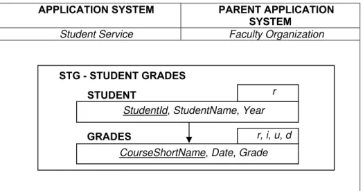
In the following example, we illustrate a form type created in an IIS*Case project named FacultyIS, and the corresponding IIS*CDesLang program. Figure 1 presents a form type defined in the child application system Student Service of a parent application system Faculty Organization. It refers to information about student's grades (STG). It has two component types: STUDENT representing instances of students, and GRADES, representing instances of grades for each student.
APPLICATION SYSTEM PARENT APPLICATION SYSTEM
Student Service Faculty Organization
Fig. 1. A form type in the application system Student Service STUDENT
GRADES
StudentId, StudentName, Year
CourseShortName, Date, Grade
STG - STUDENT GRADES
r
By the form type STG, we allow having students with zero or more grades. Component type attributes are presented in italic letters. StudentId is the key of the component type STUDENT, while CourseShortName is the key of GRADES. By this, each grade is uniquely identified by CourseShortName
within the scope of a given student. Allowed database operation for STUDENT is only read (shown in a small rectangle on the top of the rectangle representing the component type), while the allowed database operations for GRADES are read, insert, update and delete.
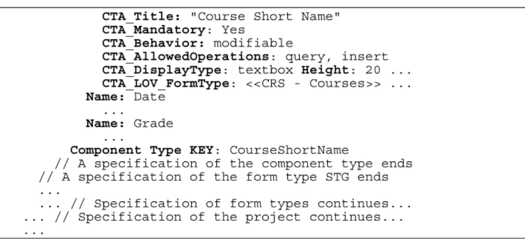
Figure 2 presents a fragment of IIS*CDesLang program that corresponds to the form type specification from Figure 1. Despite that it is just a fragment we present the program in a way to cover the specification as a whole. Just repeating segments of the specification, as well as a number of display and LOV properties are omitted. To better explain various segments of the program, we have included in-line comments tagged with the symbol //. In the following text, we give a textual explanation of the program from Figure 2.
Firstly, the project FacultyIS with its two application systems is specified. The first one is a specification of the Faculty Organization application system and then a specification of its child application system Student Service. After specifying the application system properties Description and Type, a list of form type specifications included in Student Service is given. In Figure 2 it is presented a specification of the form type STG – Student Grades only. Each form type specification includes properties Title, UsageType that may be
program or menu, UsageFrequency and ResponseTime, and a list of component type specifications. A parent component type STUDENT and its child component type GRADES are specified in the form type STG – Student Grades.
The first, Title and Allowed Operations properties are specified for a component type. By this, read is the only allowed database operation for the component type STUDENT. After that, a list of display and other UI properties is specified. When generates UI of a transaction program of the form type
STG – Student Grades, the component type STUDENT is to be positioned in a new window (Position property) and presented in a field layout style (DataLayout property). A window is to be centred to its parent window (Window Position property). Search functionality for student records is allowed (Search Functionality property), while multiple deletions (Massive Delete Functionality property) and retaining last inserted record in the screen form (Retain Last Inserted Record property) functionalities for student records are disabled. After the specifications of display and UI properties, it follows a list of specifications of component type attributes.
For each component type attribute we specify its name (Name property), title (CTA_Title property), if it is mandatory or optional for entering values on the screen form (CTA_Mandatory property), behavior (CTA_Behavior
property) and allowed operations on the screen form ( CTA_AllowedOpera-tions property). A set of display and LOV properties (preceded by
Project: Faculty IS
Application System: Faculty Organization
Description: "A unit of a Faculty IS" Type: ProjectSubsystem
... // Specification of the appl. system continues... ...
Application System: Student Service
is-child-of <<Faculty Organization>> Description: "A unit of Faculty Organization subsys."
Type: ProjectSubsystem ...
... // A list of form types is specified here ...
// A specification of the form type STG begins FormType: "STG - Student Grades"
Title: "Catalogue of student grades"
UsageType: Program Considered-in-db-design: Yes
UsageFrequency: 1 Unit: seconds
ResponseTime: 1 Unit: seconds
// A specification of the component type begins
ComponentType: STUDENT
Title: "Student Records"
Allowed Operations: read
Position: newWindow
DataLayout: FieldLayout
Window Position: Center
Search Functionality: Yes
Massive Delete Functionality: No
Retain Last Inserted Record: No
Component Type Attributes:
Name: StudentID
CTA_Title: "Student Id."
CTA_Mandatory: Yes
CTA_Behavior: queryOnly
CTA_AllowedOperations: query
CTA_DisplayType: textbox Height: 20 ...
// More display properties are omitted ...
CTA_LOV_FormType: <<STD - Student>> ...
// More LOV properties are omitted ...
Name: StudentName
...
Name: Year
...
Component Type KEY: StudentID
// A specification of the component type ends
// A specification of the component type begins
ComponentType: GRADES is-child-of <<Student>>
NoOfOccurrences: (0:N)
Allowed Operations: read, insert, update, delete
Position: sameWindow
Layout Relative Position: Bottom-to-parent
DataLayout: TableLayout
Window Position: Center
Search Functionality: Yes
Massive Delete Functionality: No
Retain Last Inserted Record: Yes
Component Type Attributes:
CTA_Title: "Course Short Name"
CTA_Mandatory: Yes
CTA_Behavior: modifiable
CTA_AllowedOperations: query, insert
CTA_DisplayType: textbox Height: 20 ...
CTA_LOV_FormType: <<CRS - Courses>> ...
Name: Date
...
Name: Grade
...
Component Type KEY: CourseShortName
// A specification of the component type ends // A specification of the form type STG ends ...
... // Specification of form types continues... ... // Specification of the project continues... ...
Fig. 2. A fragment of IIS*CDesLang program that correspond to the form type in Fig. 1
After the list of component type attributes, the list of component type constraints is given. It may include the specifications of key, uniqueness and check constraints. In the example shown in Figure 2, only component type keys are specified for STUDENT and GRADES by the property Component Type KEY.
5. The Attribute Grammar Specification of IIS*CDesLang
In this section, an AG specification of IIS*CDesLang, created by VisualLISA will be described. The IIS*Case concepts, introduced along the previous section, will now be mapped into IIS*CDesLang symbols establishing a correspondence between domain concepts and non-terminal or terminal grammar symbols in the systematic way described in [9].
Although the same term "attribute" is used in this paper as a well known concept in two different contexts: (i) in Section 4, in the domain of databases and information systems and (ii) in Section 5, as a concept of AGs, it is important to notice that it is generally speaking the same concept. It is used in the sequel (associated with symbols) in the context of grammars, in the same way as it is in the context of object-oriented models/programs, or databases; in all of these contexts, the notion of attribute denotes a characteristic that gives semantic to the thing we are formally describing a grammar symbol, a class, or even a relation scheme/entity type.
As it can be inferred from AG definition above, to write a complete attribute grammar for a real size programming language is a systematic and disciplined work. However it is time consuming and repetitive task.
Although not a complex task, in a case of real size grammar it tends to be time consuming process requiring a careful work. This inconvenience discourages language designers to use AGs. Such an attitude prevents them of resorting to systematic ways to implement the languages and their supporting tools [22].
To overcome this drawback, for modeling the new DSL we use a Visual Language (VL) and its respective VPE called VisualLISA, as it is proposed in [21], and conceived in [19]. The idea of introducing VL is not only about having a nice visual depiction that will be translated into a target notation latter on, but also having a possibility of checking syntactic and semantic consistency.
VisualLISA environment offers a visually oriented and non-errorprone way for AG modeling and an easy translation of AG models into a target language. Three main features of VisualLISA are: (i) syntax validation, (ii) semantics verification and (iii) code generation. The syntax validation restricts some spatial combinations among the icons of the language. In order to avoid syntactic mistakes, the model edition is syntax-directed. The semantics verification copes with the static and dynamic semantics of the AG meta-language. Finally, the code generation produces code from the drawings sketched up. The target code would be LISA specification language (LISAsl), the meta-language for AG description under LISA generator [19]. LISAsl specification is passed to the LISA system [16, 20] in a straightforward step.
In this section, we discuss how VisualLISA is used to create IIS*CDesLang. We only present a small set of productions and semantic calculations, to show how we use the visual editor to model the language. Before that we present a short description of VisualLISA look and feel, and main usage.
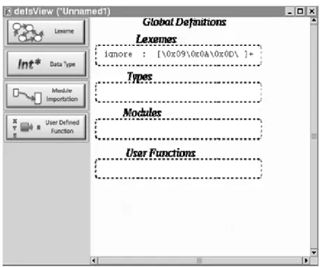
Figure 5, to the editing area. To draw the computations links should connect some of the (input) attributes to an (output) attribute using functions. Functions can be pre-defined, but sometimes it is necessary to resort to user-defined functions that should be described in defsView – sub-window presented in Figure 6. In this sub-window it is also possible to import packages, define new data-types or define global lexemes.
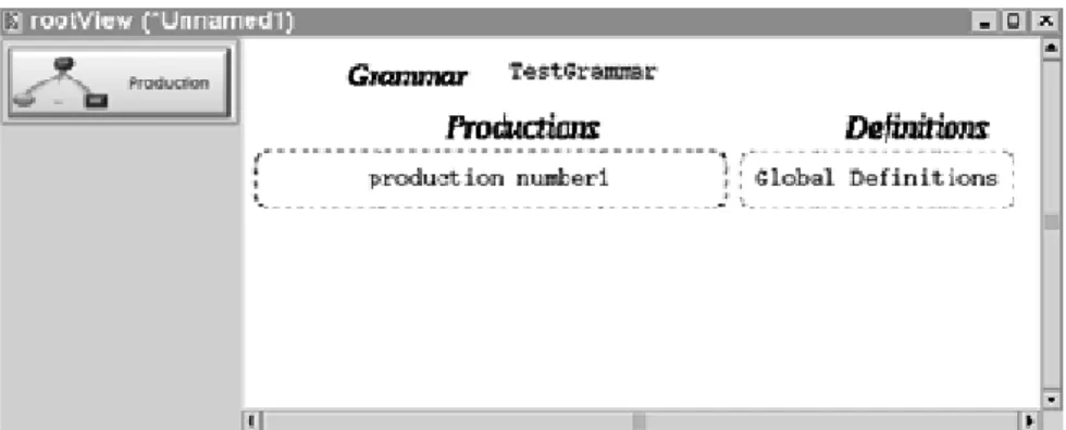
Fig. 3. VisualLISA subwindow for declaring productions
Fig. 5. VisualLISA editing area subwindow
Fig. 6. VisualLISA subwindow for creating user defined functions, importing packages, defining new data-types and global lexemes
formalized and verified using the visual editor: “The application types associated to application systems should be previously defined”.
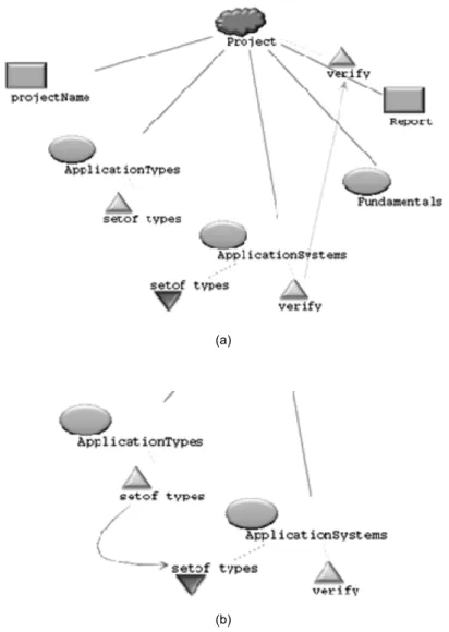
For a thorough understanding of the upcoming example, here follows a brief overview of the visual symbols semantics. The cloud-shaped symbol is the left-hand side (LHS) of a production; the squares and ellipses are the terminals and the non-terminals at the right-hand side (RHS) of a production, respectively. The triangles represent the attributes: inherited attributes are inverted triangles, while the other triangles are synthesized attributes. The explosion-shaped symbol represents a function to compute the attributes value. Concerning the lines and the arrows: the simple lines represent the connection between the LHS and the RHS symbols; the dashed lines represent the connections between the symbols and the synthesized and the inherited attributes; the full arrow means the copy of a value from an attribute to another; the dashed arrow with a number over it represents an ordered argument of a function and, finally, the full arrow from an explosion-shaped symbol stands for the output of the function.
Figure 7 shows the first production of IIS*CDesLang – the one having the grammar axiom as the tree root. The root Project (see Figure 7.a) derives in three other non-terminal symbols (ApplicationTypes, ApplicationSystems, and
Fundamentals) and two terminals. Apart from that structural description, the production shown in Figure 7.a states that the attribute verify of the root symbol has the same value as the synthesized attribute verify (triangle) of the non-terminal ApplicationSystems. In Figure 7.b it is presented a detail of the same production, specifying that the inherited attribute setof_types (inverted-triangle) of non-terminal ApplicationSystems, inherits the value of the attribute
setof_types of the non-terminal ApplicationTypes.
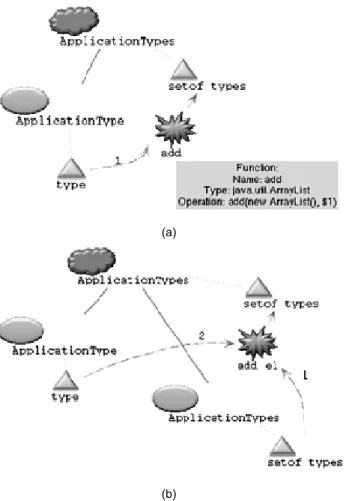
In Figure 8, we present how the attribute setof_types of the non-terminal
AplicationTypes, is computed. First notice that the production for this non-terminal has two options: (i) a non-recursive one, where AplicationTypes
derives only one AplicationType (Figure 8.a) and (ii) a recursive case, where the left-hand side non-terminal derives into an AplicationType and recursively calls itself.
In this production, we are interested in collecting the application type names that can be associated to the application systems, as explained before. To describe this in VisualLISA we created a function that adds a string to a list, and this function is used to collect the types that are synthesized from each non-terminal ApplicationType. The explosion symbol denotes the function, the dashed-arrows define the arguments of these functions, and the straight arrows denote to which attribute the output of the function is assigned. The numbers in the dashed-arrows indicate the order of the arguments in the function, which are then used as ‘$i’ in the function body, where $1 is the first function argument and $2 the second; in general, $i represents the value of the i-th argument.
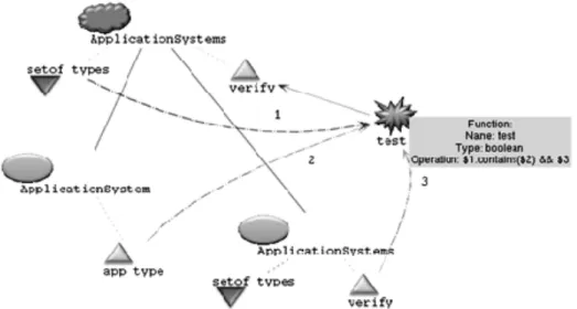
contextual condition that we try to verify in this example. Figure 9 presents the recursive option of the production with the ApplicationSystems as LHS symbol.
(a)
(b)
(a)
(b)
Fig. 8. Production structure and computation of attribute setof_types of the element ApplicationTypes. (a) non-recursive case; (b) recursive case.
From each application system we synthesize its application type (attribute
app_type). Then, we use the inherited attribute setof_types and the value that results from applying this computation to the rest of the application systems in the language, to inject these three arguments in a function that tests if the
setof_types ($1 in the operation description of Figure 9) contains the value of the synthesized attribute app_type ($2 in the operation description). As this operation returns a boolean value, we check using the logic and operation, if this value and the value of the attribute verify ($3 in the operation description) are both true. The output of the function is also a Boolean and is assigned to attribute verify of the LHS symbol.
Fig. 9. Recursive case for production of the symbol ApplicationSystems and computation of the attribute verify.
Although the drawings presented in Figures 7 to 9 have been formally constructed, for those that read the visual grammar it is not necessary to know if attributes are synthesized or inherited, neither the way evaluation rules are built – it is enough to understand the way they are connected to understand the new language semantics. The remaining parts of the formalization follows the same structure as the one presented in this section.
To develop incrementally a DSL using VisualLISA is very easy. Just define a new set of attributes (corresponding to the next semantic step) and the respective evaluation rules and draw this new semantic specification over a syntax tree (a production) previously created. VisualLISA environment will automatically add this new component to the ones existing for the same symbols. However VisualLISA does not include any operator for grammar inheritance or symbol/production extension in LISA style.
With VisuaLISA we defined a model of IIS*CDesLang PIM concepts. The IIS*CDesLang productions were visually modelled, checked and translated to LISA specifications. This model can be turned into a valid AG, and in a straightforward step, we have not only a new language, but also a compiler for the language.
We list below the textual format for the most important IIS*CDesLang productions of the AG outputted by VisualLISA environment. Those are the productions that in general cover the concepts of: project, application system, form type and component type. Notice that we transcribe them in a neutral AG-format to avoid that the reader must learn LISA syntax.
The first production is:
It defines a project specifying a name (ProjectName), a set of possible types of application systems (ApplicationType), a set of application systems created in the scope of a project (ApplicationSystem), fundamental concepts (Fundamentals) and category of a repository report (Reports).
The production defining the application system is:
ApplicationSystem AppSystemName AppSystemDescription
ApplicationTypeName FormTypes BusinessApplication+ ChildAppSystem+ RelationScheme+ JoinDependency+ ClosureGraph Reports
It specifies a name (AppSystemName), a description (AppSystem Description), a type of application system (ApplicationTypeName), a category of a form type (FormTypes), a set of business applications (BusinessApplication), a set of child application systems (ChildAppSystem), a set of generated relation schemes (RelationScheme), a set of created join dependencies (JoinDependency), a closure graph (ClosureGraph) and category of application system specific reports (Reports).
At this point, it is needed to verify if the application system type specified for an application system belongs to the set of possible types:
ApplicationSystem.ApplicationTypeName.value belong_to {set_of(ApplicationType.ApplicationTypeName .value)}
Just as an illustration, we give here selected productions covering the form type and component type concepts:
FormTypes OwnedFormType+ ReferencedFormType+
OwnedFormType FormTypeName FormTypeTitle FTFrequency FTResponseTime FTParameter+ CalledFormType+ FTUsage
FTUsage Menu | Program
Program ComponentTypeTreeStructure ConsideredInDBSchDesign
ComponentTypeTreeStructure ComponentType+
ComponentType CTName CTParent NoOfOcurrences
CTTitleAllowedOperations ComponentDisplay ItemGroup+ComponentTypeAttribute+
ComponentTypeKey+ ComponentTypeUnique+ ComponentTypeCheckConstraint
6. Conclusion
AGs are widely used to specify the syntax (by the underlying Context Free Grammar) and the semantics (by the set of attributes and theirs computation rules and contextual conditions) of computer languages. This formalism is well defined and so its usage is completely disciplined; but, more than that, it has the unique property of supporting the specification of syntax and semantics under the same framework. Moreover, an AG can be automatically transformed into a program to process the sentences of the language it defines.
The research presented in this paper resulted from the collaborative research project between Serbia and Portugal. To formally describe the Integrated Information Systems CASE Tool (IIS*Case) – a model driven software tool that provides IS modeling and prototype generation developed at University of Novi Sad – we define a DSL, named IIS*CDesLang, that encompasses problem domain concepts and rules that are applied in the conceptual IS design provided by IIS*Case. In the paper, we present such a meta-language resorting to a VPE for attribute grammar specifications, named VisualLISA, developed at University of Minho. VisualLISA makes the process of AG development easier and safer; it allows the drawing of the AG productions (grammar rules) in the form of attributed trees decorated with attribute evaluation rules. These visual productions are syntactically and semantically checked for correctness.
Currently, we are completing the IIS*CDesLang AG specification to cover all the IIS*Case. After that, we will resort to the compiler generator system LISA to produce a compiler for IIS*CDesLang.
On the basis of the problem domain knowledge embedded in the AG, the generated compiler will also provide semantic analyses of the designed specifications and further assist designers in raising the quality of their work. Two characteristic examples are domain compatibility analysis and check constraint equivalence analysis. We plan to include a textual editor for IIS*CDesLang into IIS*Case, and integrate into it the generated compiler to couple IIS*Case repository with the formal IIS*CDesLang descriptions.
Moreover, as future work we plan to build a translator from IIS*Case Visual PIM specifications into textual IIS*CDesLang descriptions. This will allow to verify the specifications correctness without writing them manually in IIS*CDesLang. Also, it will be possible and interesting to implement the automatic generation of PIM specifications from IIS*CDesLang descriptions.
References
1. Aleksić, S., Luković, I., Mogin, P., Govedarica, M.: A Generator of SQL Schema Specifications. Computer Science and Information Systems (ComSIS), Consortium of Faculties of Serbia and Montenegro, Novi Sad, Serbia, ISSN:1820-0214, Vol.4, No. 2, 79--98. (2007)
2. Banović J.: An Approach to Generating Executable Software Specifications of an Information System. Ph.D. Thesis. University of Novi Sad, Faculty of Technical Sciences in Novi Sad. (2010)
3. Bézivin J., On the unification power of models, Software and Systems Modeling, Vol. 4, No. 2, 171--188. (2005)
4. Deursen van, A., Klint, P. Visser, J.: Domain-Specific Languages: An Annotated Bibliography. ACM SIGPLAN Notices, Association for Computing Machinery, USA, Vol. 35, No. 6, 26--36. (2000)
5. Eclipse Modeling Framework [Online] Available:
http://www.eclipse.org/modeling/emf/ (current April, 2011)
6. Jouault F., Bézivin J.: KM3: a DSL for Metamodel Specification, In: Proceedings of 8th IFIP International Conference on Formal Methods for Open Object-Based Distributed Systems, Bologna, Italy, Springer LNCS 4037, 171--185. (2006) 7. Knuth, D. E.: Semantics of Context-free Languages. Theory of Computing
Systems, Vol 2, No. 2, 127--145. (1968)
8. Krahn H., Rumpe B., Völkel S.: Roles in Software Development using Domain Specific Modelling Languages, In: Proceedings of 6th OOPSLA Workshop on Domain-Specific Modeling, Portland, USA, 150--158. (2006)
9. Kosar T., Mernik M., Henriques P.R., Varanda Pereira M.J, Žumer V.: Software development with grammatical approach. Informatica, ISSN: 1854-3871, Vol. 28, No. 4, 39--404. (2004)
10. Kosar T., Oliveira N., Mernik M., Varanda Pereira M.J., Črepinšek M., da Cruz D., Henriques P.R.: Comparing General-Purpose and Domain-Specific Languages: An Empirical Study. Computer Science and Information Systems (ComSIS), Consortium of Faculties of Serbia and Montenegro, Novi Sad, Serbia, ISSN:1820-0214, Vol. 7, No. 2, 247--264. (2010)
11. Luković I.: From the Synthesis Algorithm to the Model Driven Transformations in Database Design, In: Proceedings of 10th International Scientific Conference on Informatics (Informatics 2009), Herlany, Slovakia, ISBN 978-80-8086-126-1, 9--18. (2009)
12. Luković, I., Mogin, P., Pavićević, J., Ristić, S.: An Approach to Developing Complex Database Schemas Using Form Types. Software: Practice and Experience, John Wiley & Sons Inc, Hoboken, USA, DOI: 10.1002/spe.820, Vol. 37, No. 15, 1621--1656. (2007)
13. Luković, I., Ristić, S., Aleksić, S., Popović, A.: An Application of the MDSE Principles in IIS*Case. In: Proceedings of III Workshop on Model Driven Software Engineering (MDSE 2008), Berlin, Germany, TFH, University of Applied Sciences Berlin, 53--62. (2008)
14. Luković, I., Ristić, S., Mogin, P., Pavićević, J.: Database Schema Integration Process – A Methodology and Aspects of Its Applying. Novi Sad Journal of Mathematics, Serbia, ISSN: 1450-5444, Vol. 36, No. 1, 115--150. (2006)
16. Mernik, M., Lenič, M., Avdičaušević, E., Žumer, V.: LISA: An Interactive Environment for Programming Language Development. In: Proceedings of Compiler Contruction, LNCS Vol. 2304, 1--4. (2002)
17. Meta-Object Facilty [Online] Available: http://www.omg.org/mof/ (Current: April, 2011)
18. MetaCase Metaedit+ [Online] Available: http://www.metacase.com/ (Current: April, 2011)
19. Oliveira, N. Varanda Pereira, M.J., Henriques, P.R., Cruz, D., Cramer, B.: VisualLISA: A Visual Environment to Develop Attribute Grammars. Computer Science an Information Systems Journal, Special Issue on Compilers, Related Technologies and Applications (ComSIS), Lukovic, I. and Leitão A, Slivnik B. (Guest Eds.), ISSN:1820-0214, Vol. 7, No. 2, 265--289. (2010)
20. Varanda Pereira, M.J., Mernik, M., Cruz, D., Henriques, P.R.: Program Comprehension for Domain-Specific Languages. Computer Science and Information Systems (ComSIS), ISSN:1820-0214, Vol. 5, No. 2, 1--17. (2008) 21. Varanda Pereira, M.J., Mernik, M., Cruz, D., Henriques, P.R.: VisualLISA: a Visual
Interface for an Attribute Grammar based Compiler-Compiler, In: Proceedings of 2nd Conference on Compilers, Related Technologies and Applications (CoRTA08), IPB, Bragança, Portugal, 265--289. (2008)
22. Henriques P.R., Pereira Varanda M.J., Mernik M., Lenič M., Gray J., Wu H.: Automatic Generation of Language-based Tools using LISA. IEE Proceedings – Software, Vol. 152, No. 2, pp. 54--69. (2005)
23. The Generic Modeling Environment [Online] Available:
http://www.isis.vanderbilt.edu/Projects/gme/ (Current April, 2011)
24. Popović A.: A Specification of Visual Attributes and Business Application Structures in the IIS*Case Tool. Mr (M.Sc.) Thesis. University of Novi Sad, Faculty of Technical Sciences in Novi Sad. (2008)
Ivan Luković received his M.Sc. (5 year, former Diploma) degree in Informatics from the Faculty of Military and Technical Sciences in Zagreb in 1990. He completed his Mr (2 year) degree at the University of Belgrade, Faculty of Electrical Engineering in 1993, and his Ph.D. at the University of Novi Sad, Faculty of Technical Sciences in 1996. Currently, he works as a Full Professor at the Faculty of Technical Sciences at the University of Novi Sad, where he lectures in several Computer Science and Informatics courses. His research interests are related to Database Systems and Software Engineering. He is the author or coauthor of over 75 papers, 4 books, and 30 industry projects and software solutions in the area.
Maria João Varanda Pereira ...
Nuno Oliveira ...
Daniela da Cruz ...