BJRS
RADIATION SCIENCES
06-02 (2018) 01-18Accepted for publication: 2018-04-16
A study on the cost of concrete shielding in a standard
radiotherapy facility room
Eduardo de Paiva
aa Instituto de Radioproteção e Dosimetria/Divisão de Física Médica, 22783-127, Rio de Janeiro, Rio de Janeiro, Brazil
ABSTRACT
Ionizing radiations produced by particle accelerators is widely used for the treatment of cancer. In particular high-energy photon beams generated by electron linear accelerators play an important role in external beam radiation therapy, provided that millions of people will undergo cancer in the next decades and radiotherapy is the major kind of treatment used worldwide. An interesting question is how to estimate the thicknesses of the walls of the facility room in order to prevent their vicinities to receive a radiation dose above the permissible levels. In this work we present a simplified general formalism for the estimation of the concrete wall thicknesses of a facility room housing medical linear accelerators that produce high-energy photon beams. A computer code based on FORTRAN programming language was developed, which allow us to handle with all the input parame-ters in a fast and simple way. Calculations were carried out first, assuming that all patients are treated with con-ventional radiotherapy, and second considering the inclusion of IMRT (30% patients) and VMAT (20%) tech-niques. Results indicated an increase of ~19% in total cost of concrete when the energy varies from 4 to 30 MeV (only conventional); an increase of ~25% when the energy increases from 4 to 30 MeV (conventional plus IMRT and VMAT), and a maximum increase of ~6% after the inclusion of the two special procedures compared with the conventional alone. The overall results have also shown a slight linear growth of the total volume and associ-ated cost of concrete shielding with the surface available to construct the facility vault for both modes of treat-ment.
1. INTRODUCTION
Radiotherapy is a medical practice that uses doses of ionizing radiation for the treatment of can-cer. Radiotherapy can be performed with the use of radiation originated from radioisotopes or from large particle accelerators. Particle accelerators can produce clinical beams of massive particles such as electrons, pions or protons, or particles of no mass such as photons. In this later case, elec-tron linear accelerators (linacs) produce elecelec-trons that strike a heavy metal target to generate clinical photon beams of high-energies varying from units up to some tens of MeV(1 MeV refers to the maximum energy of a photon produced by the process of bremsstrahlung when an electron acceler-ated to a voltage of 1 MV hits a metallic target, and along this work we use indistinctly MeV or MV). These high-energy therapeutic photon beams play an important role in external beam radia-tion therapy (or teletherapy) provided that the rate of new cases of cancer all over the world is in fast increasing [1]. The use of linear accelerators in radiotherapy imposes an interesting question that is how to estimate the thicknesses of the barriers of the facility room housing radiation treat-ment machines in order to prevent that its vicinity do not receive doses of ionizing radiation above the legal permissible levels.
The aim of this study is to present a detailed investigation of the thicknesses of the barriers of a standard radiotherapy facility room housing linear accelerators of electrons producing photons with the single high endpoint energies of 4, 6, 8, 10, 12, 15, 18, 20, 25 and 30 MeV and the associated total costs using ordinary concrete as the material of shielding. Starting at 4 MeV, calculations were carried out for a standard facility room and using three values of workloads. Results of total costs are shown first considering 100% of patients treated with no special procedures, and second consid-ering the addition of the Intensity Modulated Radiation Therapy (IMRT) and Volumetric Modulated Arc Therapy (VMAT) techniques. In this attempt a routine calculation was developed using FORTRAN programming language, whose some versions of compiler can be freely downloaded from the web, that allow us easily to modify the input parameters, such as dose rate limit, workload, occupancy and use factors, width, length and height of the room.
2. MATERIALS AND METHODS
2.1. THE BARRIERS THICKNESSESIn Figures 1 and 2 are depicted the geometry of the radiotherapy facility room used in this study, and in what follows we described the general expressions used for the calculation of the bar-riers thicknesses. The coefficient of transmission through the primary barrier can be written as [2, 3]
WUT Pd
Bprim prim
2
= , (1)
where dprim is the distance from the source to the point in the external face of the barrier; P is the
permissible shielding design goal, W is the workload (the amount of radiation output per week of the X-ray source), and T and U are the dimensionless occupancy and use factors (respectively, the fraction of time that a person remains in the protected area while the beam is on and the fraction of time that the beam is directed to the barrier).
The secondary barriers are that exposed only to stray radiations. There are two main types of these radiations of interest in radiotherapy with the use of linear accelerators that is the radiation that escapes from the accelerator head (leakage radiation) and the radiation that scatters from the patient or phantom (scattered radiation). The coefficient of transmission
B
Lfor the leakage radiation is written as WUT Pd B L L 3 2 10− = . (2)Here dL is the distance from the isocenter to the point of interest in the external side of the barrier;
P, W, U and T have the same meaning as in Equation (1), and the factor 10-3 accounts for the
as-sumed 0.1% of leakage radiation through the shielding of the accelerator head [4]. When special procedures are incorporated into the treatment the workload for leakage can be much higher than that for conventional treatment due to the large quantity of monitor units per dose used [4].
Consid-ering the IMRT and VMAT procedures in addition to the conventional mode the workload for leak-age can be written as
𝑊𝐿 = 𝑊𝑐𝑜𝑛𝑣+ 𝐶𝐼𝑊𝐼𝑀𝑅𝑇+ 𝐶𝑉𝑊𝑉𝑀𝐴𝑇, (3)
where CI and CV are the IMRT and VMAT modulation factors.
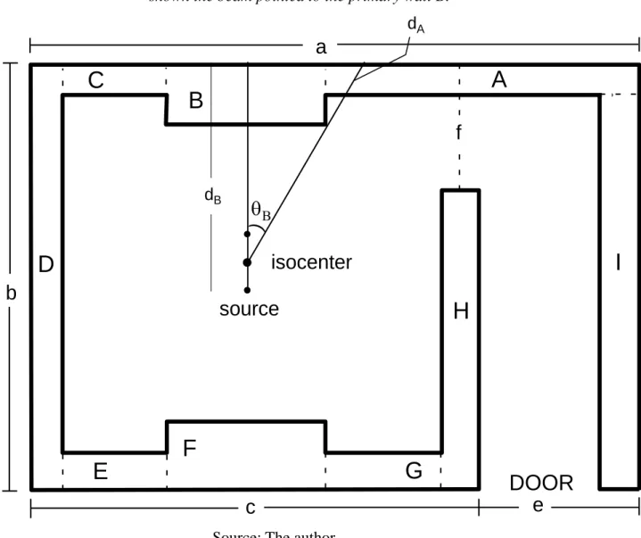
Figure 1: The geometry of a radiotherapy facility room used throughout calculations. It is shown the beam pointed to the primary wall B.
Source: The author.
A
B
C
D
E
F
G
H
I
DOOR
a
b
c
e
f
source
isocenter
)
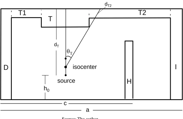
dA dBFigure 2: A lateral view of the room used to calculate the primary roof barrier thickness T
and the secondary barriers T1 and T2.
Source: The author.
In an analogue way we can write for the radiation scattered in the patient or phantom the relation
F WUT d Pd coef B scat scat 400 1 2 sec2 = , (4)
where dscat and dsec are respectively the distances from the source to the scattering medium (located
at the isocenter, a fixed point about which the gantry can rotate 360 degrees) and from the scattering medium to the point to be protected; F is the field area at the isocenter, and coef is the fraction of the primary beam radiation dose that scatters from the patient at a certain angle. Provided that the coefficients of transmission are known the evaluation of the primary (tprim) or leakage (tleak) barrier
thickness is thus obtained from the equations
T2
T
T1
D
H
I
a
c
source
isocenter
h
0h
)
dT2 dT𝑛 = −𝑙𝑜𝑔10(𝐵) (5)
and
𝑡 = 𝑇𝑉𝐿1+ (𝑛 − 1) × 𝑇𝑉𝐿𝑒, (6)
where B and t stand for primary or leakage, n is the number tenth-value layers (TVL), TVL1 and TVLe are the first and the equilibrium TVLs, which depend on the energy of the beam and on the
desired material used for shielding. For the scattered radiation we have
𝑛 = −𝑙𝑜𝑔10(𝐵𝑠𝑐𝑎𝑡) (7)
and
𝑡𝑠𝑐𝑎𝑡 = 𝑛 × 𝑇𝑉𝐿𝑠𝑐𝑎𝑡. (8)
When two different sources contribute simultaneously to the radiation dose at the same point the “two source” rule is usually used. This rule is a rule of thumb and states that if the thicknesses duo to the two sources differ by one or more TVL (the greater TVL between the two sources), the greater thickness is used; if the thicknesses differ by less than one TVL we add one HVL (half-value layer) to the greater thickness. In our model this rule is applied to the estimation of wall thicknesses A, C, D, E, G, I, T1 and T2.
The room has width a and length b; c is the central width of the room where the linac is lo-cated; e is the width of the door plus the thickness of wall I; f is the distance from the end of wall H to the external face of wall A, and for all energies the isocenter is fixed at (c/2, b/2). The walls B and F are primary barriers and walls A, C, D, E, G, H and I are secondary barriers. In Figure 2 is shown a lateral view of the facility room, where T is a primary barrier and T1 and T2 are secondary barriers. The facility room has a constant height h and the source or target is at a fixed distance h0
taking into consideration the primary radiation beam when the gantry is directed upward, and the secondary leakage and scattered radiation in the same way as described above for the vertical barri-ers.
Next in Table 1, we summarize the areas behind the barriers, the shielding design goals [5] and the occupancy and use factors for each barrier shown in Figures 1 and 2.
Table 1: Description and type of each region behind the walls, with the correspondent
shielding design goal, and use and occupancy factors.
Location Description Type P(mSv/week) U T
A Parking lot Uncontrolled 0.02 1 1/16
B Parking lot Uncontrolled 0.02 1/7 1/16
C Parking lot Uncontrolled 0.02 1 1/16
D Garden Uncontrolled 0.02 1 1/16
E Control room Controlled 0.4 1 1
F Control room Controlled 0.4 1/7 1
G Control room Controlled 0.4 1 1
I Waiting room Uncontrolled 0.02 1 1/2
T1 Offices Uncontrolled 0.02 1 1/2
T Offices Uncontrolled 0.02 2/7 1/2
2.2. THE DISTANCES
The distances are chief quantities (in meters) necessary to implement the calculation and are de-fined and summarized as follows.
- dB (dF) is the distance from the source or target to the point to be protected beyond barrier B
(F).
𝑑𝐵= 𝑑𝐹 = 𝑏
2+ 1. (9)
- dscat is the distance from the source to the isocenter or patient, and it is always equal to 1.
- dsec is the distance from the isocenter or patient to the point to be protected. dsec = dA or dC or dD or dE or dG or dI.
- dA (dc) is the distance from the isocenter or patient to the point after wall A (C), tangent to
the edge of wall B.
𝑑𝐴= 𝑑𝐶 = 𝑏
2 cos 𝜃𝐵, (10)
θB is the angle between the line representing dA and the central axis pointed to B.
- dG (dE) is the distance from the isocenter or patient to the point after wall G (E), tangent to
the edge of wall F.
𝑑𝐺 = 𝑑𝐸 = 𝑏
2 cos 𝜃𝐹, (11)
θF is the angle between the line representing dG and the central axis pointed to F.
𝑑𝐷 = 𝑐
2. (12)
- dI is the distance from the isocenter or patient to the point to be protected beyond wall I.
𝑑𝐼 = 𝑐
2+ 𝑒. (13)
- dT is the distance from the source to the point to be protected beyond barrier T (roof) with
the beam directed vertically up.
𝑑𝑇 = ℎ − ℎ0. (14)
- dT2 (dT1) is the distance from the isocenter or patient to the point to be protected beyond wall
T2 (T1), tangent to the edge of wall T.
𝑑𝑇2 = 𝑑𝑇1 = 𝑑𝑇−1
cos 𝜃𝑇, (15)
θT is the angle between the line representing dT2 and the central axis pointed to T.
2.3. THE WIDTHS OF THE BARRIERS
The width of each barrier (in meters) is defined as follows. The letter t stands for thickness, and when applicable always considering the two source rule.
- for walls B, F and T, widths are determined merely by the projection of the maximum field size rotated of 45 degrees.
- wall C
𝑤𝑖𝑑𝑡ℎ 𝐶 =𝑐2−𝑤𝑖𝑑𝑡ℎ 𝐵2 − 𝑡𝐷. (16) - wall D
𝑤𝑖𝑑𝑡ℎ 𝐷 = 𝑏. (17) - wall E 𝑤𝑖𝑑𝑡ℎ 𝐸 =𝑐 2− 𝑤𝑖𝑑𝑡ℎ 𝐹 2 − 𝑡𝐷. (18) - wall G 𝑤𝑖𝑑𝑡ℎ 𝐺 =𝑐 2− 𝑤𝑖𝑑𝑡ℎ 𝐹 2 − 𝑡𝐻. (19) - wall H 𝑤𝑖𝑑𝑡ℎ 𝐻 = 𝑏 − 𝑓. (20) - wall I 𝑤𝑖𝑑𝑡ℎ 𝐼 = 𝑏 − 𝑡𝐴. (21) - wall A 𝑤𝑖𝑑𝑡ℎ 𝐴 = 𝑎 −𝑐 2− 𝑤𝑖𝑑𝑡ℎ 𝐵 2 . (22) - wall T1 𝑤𝑖𝑑𝑡ℎ 𝑇1 =𝑐 2− 𝑤𝑖𝑑𝑡ℎ 𝑇 2 − 𝑡𝐷. (23) - wall T2 𝑤𝑖𝑑𝑡ℎ 𝑇2 = 𝑎 −𝑐 2− 𝑤𝑖𝑑𝑡ℎ 𝑇 2 − 𝑡𝐼. (24)
2.4. AN OUTLINE OF THE CODE
Tables of first and equilibrium primary TVL’s, TVL’s for leakage radiation, scattered TVL’s and scatter fractions are tabulated within the code and they were taken respectively from tables B.2, B.7, B.5a and B.4 of NCRP No 151 [4]. The parameters a, b, e, f, h and h0 and the cost
(in US$) of one cubic meter of ordinary concrete are defined in the preamble. Some geometrical constraints are imposed to the barriers along calculations in order to prevent inconsistencies as for example to avoid the machine head to touch the primary barriers, and to verify if the leakage and scattered radiation pass by the aperture f and reach wall A when the primary beam is directed to B.
The FORTRAN code is based on four subroutines. First, a subroutine is used to calculate the primary barriers B, F and T. The input data are the distances from the source to the points of
inter-est, the workloads, the use and occupancy factors, the dose rate limits, and the TVL’s. The output is the primary thickness.
The second subroutine is used to calculate the barrier duo to leakage radiation. The input data are the distances from the source to the points of interest, the workloads, the use and occupancy factors, the dose rate limits, and the TVL’s. The output is the leakage thickness.
The third is to determine the thickness duo to scattered radiation at patient. The input data are the distances from the isocenter to the points of interest, the workloads, the use and occupancy factors, the dose rate limits, the scatter fraction, and the TVL’s. The output is the scattered thickness.
The fourth is the application of the “two source” rule used to choose between the barrier thicknesses duo to leakage and scattered radiation for each secondary barrier.
In order to validate the code a complete example was manually performed for a single energy.
2.5. THE SIMPLIFYING ASSUMPTIONS AND APPROACHES
In this work the following conservative simplifying hypotheses and approaches are adopted.
i. Only single high-energy radiation machines are considered, and a standard design of the ra-diotherapy facility room is used.
ii. The available area to build the facility room is 𝑎 × 𝑏. Starting at 4 MeV, for all other ener-gies the wall thicknesses can only increase toward the inside.
iii. The parameters e, f, h and h0 remain constants throughout all calculations.
iv. The same and constant value of the absorbed-dose output rate is used to all energies along calculations.
v. An arbitrary value to the price of one cubic meter of common concrete is used along all cal-culations.
vi. It is assumed to wall H a fixed thickness of 1 TVL of the leakage radiation for each energy. No calculation is done for it, and it is not taking into consideration to the calculation of the thickness of wall I.
vii. The scattered radiation that reaches walls D and I comes from 90 degrees scattering of the primary beam at patient.
viii. The scattered radiation that reaches walls A, C, E and G comes from scattering of the prima-ry beam at patient at an angle defined geometrically when the incidence is horizontal. These distances are the lesser possible, tangent to primary walls edge.
ix. The values of TVL’s for primary and leakage radiation are linearly interpolated at energies whatever they are not available.
x. The values of TVL’s and scatter fractions for scattered radiation are linearly interpolated at energies and angles whatever they are not available.
xi. No obliquity of the radiation beam is considered.
xii. Walls that shield photons also shield neutrons. No contribution from neutrons is considered for the thickness of concrete walls, even at energies greater than 10 MeV.
3. RESULTS AND DISCUSSION
In this study we consider linear accelerators that generate photon beams of energies 4, 6, 8, 10, 12, 15, 18, 20, 25 and 30 MV. The thickness and volume of each wall and the total cost of common concrete (2.35g/cm3) shielding of the facility room were calculated for each single energy and con-sidering two routines of treatment. First, 100% of patients treated with no special procedures (con-ventional) and for three values of workloads, 800, 1,000 and 1,200 Gy/week. Second, 50% of pa-tients treated with conventional technique, 30% of papa-tients treated with IMRT technique and 20% treated with VMAT. As discussed above, the special procedures affect only the secondary leakage workloads, and according to Equation (3) they increase respectively to 2,080, 2,600, and 3,120 Gy/week for modulation factors CI = 5 and CV = 3 obtained from clinical experience [4,6].
The price of one cubic meter of ordinary concrete varies from region to region. In order to make the calculations as general as possible, an option was done to take it arbitrarily as US$ 100. This approach allow readers easily to obtain the total costs for any value of cubic meter of concrete. In results shown in Figures 3 and 4 the parameters a, b, e, f, h and h0 have the values (in meters): a =
15, b = 11, e = f = 2.5, h = 5.7 and h0 = 0.4.
In lower part of Figure 3 we present the total cost (in thousands of dollars) of concrete shielding as a function of the energy of the beam considering only the conventional treatment mode.
Figure 3: The total cost (in thousands of dollars) of concrete shielding plotted against the energy of the beam. Full circles, triangles and squares are results respectively for 800, 1,000 and 1,200 Gy/week conventional workloads (bottom); Empty circles, triangles and squares are results ob-tained after inclusion of the IMRT and VMAT techniques (top). The full lines are just guides to the
eyes.
Source: The author.
0
5
10
15
20
25
30
35
Energy [MeV]
35
40
45
50
T
o
ta
l
R
o
o
m
C
o
st
[
1
,0
0
0
x
U
S
$
]
35
40
45
50
55
The total cost of the room varies from US$ 39,650 at 4 MV to US$ 46,980 at 30 MV for the 800 Gy/week workload; US$ 40,430 at 4 MV to US$ 48,040 at 30 MV for the 1,000 Gy/week work-load, and US$ 41,020 at 4 MV to US$ 48,810 at 30 MV for the 1,200 Gy/week workwork-load, repre-senting a difference about 18-19% between the minimum and maximum energy to each workload. Results presented in the lower part of Figure 3 also indicate an overall difference in total cost among workloads of less than 5%. In the upper part of Figure 3 are presented the results considering the IMRT (30%) and VMAT (20%) procedures. The total cost of concrete now varies from US$ 40,460 at 4 MV to US$ 49,800 at 30 MV for the 800 Gy/week conventional workload (2,080 Gy/week leakage workload); US$ 40,850 at 4 MV to US$ 50,830 at 30 MV for the 1,000 Gy/week workload (2,600 Gy/week leakage workload), and US$ 41,540 at 4 MV to US$ 51,570 at 30 MV for the 1,200 Gy/week workload (3,120 Gy/week leakage workload), representing a difference about 23-24% between the minimum and maximum energy to each workload. Results presented in the upper part of Figure 3 also indicate an overall difference in total cost among workloads of less than 4%. Figure 3 also shows that the inclusion of the IMRT and VMAT special procedures in-crease the total cost up to 6% at 30 MV.
In the lower part of Figure 4 the results of total cost of concrete shielding obtained only for conventional treatment are presented relative to the 4 MV cost for the 800, 1,000 and 1,200 Gy/week workloads. As shown before, for the three workloads the total cost of concrete shielding at 30 MV are 18-19% greater than at 4 MV, and now the overall differences of ~5% among workloads can be seen in a more clear way. In the upper part of Figure 4 the relative costs with the inclusion of IMRT (30%) and VMAT (20%) procedures are considered for the conventional workloads of 800, 1,000 and 1,200 Gy/week (with the respective leakage workloads of 2,080, 2,600 and 3120 Gy/week). Once again it can be seen a difference in total cost among workloads of less than 4% and a total increase of about 6% at 30 MV after the inclusion of IMRT and VMAT techniques.
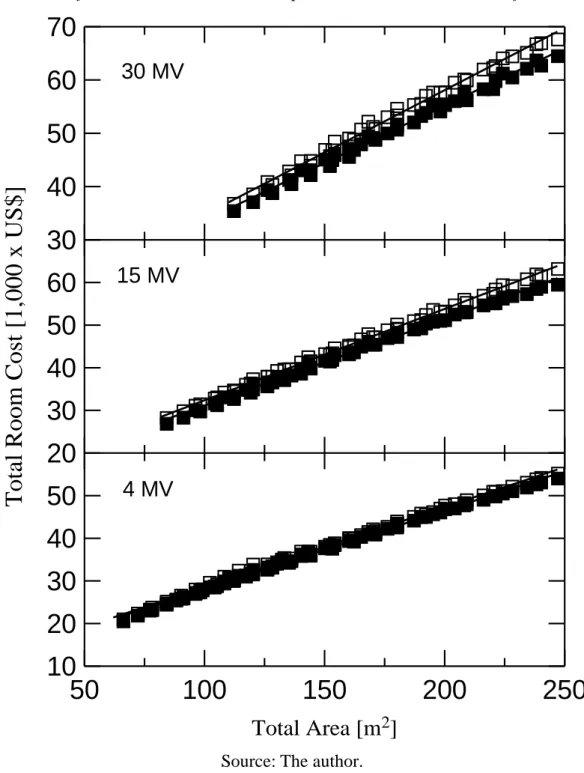
In Figure 5 is shown the total cost in thousands of dollars of concrete shielding for a 4 MV (bottom scale), 15 MV (middle scale) and 30 MV (top scale) linac as a function of the total availa-ble area at 1,000 Gy/week conventional workload (2,600 Gy/week leakage workload). The parame-ters e, f, h and h0 have the same values as before, and 11 ≤ a ≤ 20 and 6 ≤ b ≤ 14 in meters. Because
of the limiting conditions previously mentioned, the minimum area necessary to construct the room ranges from ~65 m2 to the 4 MV up to ~110 m2 to the 30 MV linac. Once again it can be seen an
Figure 4: The total cost of concrete shielding as a function of the energy of the beam. Re-sults are normalized to the 4 MeV energy. Full circles, triangles and squares are reRe-sults
re-spectively for 800, 1,000 and 1,200 Gy/week conventional workloads (bottom); Empty cir-cles, triangles and squares are results obtained after inclusion of the IMRT and VMAT
tech-niques (top). The full lines are just guides to the eyes.
Source: The author.
0
5
10
15
20
25
30
35
Energy [MeV]
1.00
1.10
1.20
R
e
la
ti
v
e
T
o
ta
l
C
o
st
1.00
1.10
1.20
1.30
Figure 5: The total cost (in thousands of dollars) of concrete shielding plotted against the available area to build the facility room. Full squares are results for a 4, 15 and 30 MV lin-ac at the fixed conventional workload of 1,000 Gy/week. Empty squares are results obtained after inclusion of the IMRT and VMAT techniques. The solid lines are linear fits to the data.
Source: The author.
50
100
150
200
250
Total Area [m
2]
10
20
30
40
50
20
30
40
50
60
T
o
ta
l
R
o
o
m
C
o
st
[
1
,0
0
0
x
U
S
$
]
30
40
50
60
70
30 MV
15 MV
4 MV
increase of total cost with energies. Considering 100% of patients treated with conventional tech-nique at 250 square meters the cost for 15 MV is about 11% greater than that for 4 MV, and for 30 MV the total cost is about 20% greater than that for 4 MV. When the IMRT (30% of patients) and VMAT (20% of patients) techniques are included the differences in cost at 250 m2 increase to 15% when the energy increases from 4 to15 MV, and increase to 25% when the energy increases from 4 to 30 MV. It can also clearly be seen a tendency of linear increase of the total cost of concrete shielding with the increasing of total available area even with the inclusion of IMRT and VMAT modes, and the slopes increase with energy.
4. CONCLUSION
In this work a routine calculation based on FORTRAN programming language was developed in order to deal with the various parameters needed to estimate the barrier thicknesses and the asso-ciated total cost of common concrete of a standard radiotherapy facility room housing medical pur-pose linear accelerators. The results of this study showed a quantitative relation of the total cost with energy, workload and area available to built the facility room. It is also shown the effect of the inclusion of special procedures such as IMRT and VMAT techniques on the total cost.
Despite the various simplifying approaches adopted throughout this numerical calculation, the results presented here can serve as a guide for users in the study of thicknesses, volumes and costs when using common concrete in shielding of radiotherapy facilities rooms. This work can either serve to estimate the supplementary amounting of shielding in an existing vault when an upgrade to a higher-energy linac is intended. At this point, we can not let to mention that this study have also a didactic attribute and may be an auxiliary tool in learning and teaching basic aspects of radiation protection.
ACKNOWLEDGMENT
REFERENCES
[1] WCRF - World Cancer Research Fund International. Available at:
<http://www.wcrf.org/int/cancer-facts-figures/worldwide-data>. Last accessed: 15 Jan. 2018.
[2] DE PAIVA, E. Princípios do cálculo de blindagem em radioterapia. Rev Bras Ens Física, v. 36, p. 1-5, 2014.
[3] DE PAIVA, E. The inverse square law and the exponential attenuation law used to the shielding calculation in radiotherapy on a high school level. The Phys Teacher, v. 54, p. 239-242, 2016.
[4] NCRP - National Council on Radiation Protection and Measurements. Structural shielding
design and evaluation for megavoltage X- and gamma-ray radiotherapy facilities. NCRP Re-port 151, Bethesda: NCRP, 2005. 246p.
[5] Comissão Nacional de Energia Nuclear. Diretrizes básicas de proteção radiológica.
CNEN-NN-3.01, Rio de Janeiro: CNEN, 2005. 21p.
[6] SALEH, Z. H.; JEONG, J.; QUINN, B.; MECHALAKOS, J.; GERMAIN, J.; DAUER, L. T. Results of a 10-year survey of workload for 10 treatment vaults at a high-throughput comprehensive cancer center. J Appl Clin Med Phys, v. 18, p. 207–214, 2017.