DISSERTATION
Master in Electrical and Electronic Engineering
Hardware/Software interface for enhanced remote
control of Android set-top-box
Ricardo Alexandre Caseiro dos Santos
DISSERTATION
Master in Electrical and Electronic Engineering
Hardware/Software interface for enhanced remote
control of Android set-top-box
Ricardo Alexandre Caseiro dos Santos
Dissertation developed under the supervision of Doctor Pedro Ant´onio Amado de Assun¸c˜ao, professor at the School of Technology and Management of the Polytechnic Institute of Leiria and co-supervision of Master Lu´ıs Manuel Conde Bento, professor at the School of Technology and Management of the Polytechnic Institute of Leiria.
Some men see things as they are and ask why? I dream things that never were and ask why not? (George Bernard Shaw)
This page was intentionally left blank.
Acknowledgements
The limited space of this acknowledgement section, of course does not allow me to thank as I should. To all the people that throughout my time at Polytechnic Institute of Leiria supported me directly and indirectly, to achieve my goals, improve as a human being and achieve this stage of my academic education. Thus, I leave some words, few but with a deep sense and feeling of thanks.
To my supervisor Dr. Pedro Assun¸c˜ao, for the valuable guidance, time spent on helping me and opportunities given, that contribute to increase my knowledge. To my co-supervisor, Pr. Lu´ıs Bento, for the cooperation in solving problems and questions that have emerged and for all the words of encouragement. To Dr. Hugo Costelha not only for the help and great guidance in this project, as well as in the Robotics Club at the ESTG, which undoubtedly contributed to my professional development. My sincere gratitude to have awakened my desire to want, always learn more and incessant will to do better.
To the Tech4Home for providing this excellent opportunity to work, evolve and con-tribute to this project, without whom this would not have been possible.
To Instituto de Telecomunica¸c˜oes (IT) - delega¸c˜ao de Leiria, on the scientific orienta-tion and equipment facilitated.
To my friend and co-worker Miguel Rasteiro, for all the support, creating an excellent working environment and the distracting moments outside the work.
To all my colleagues of Electrical and Electronic Engineering, IEEE IPLeiria Student Branch, CEEE and Robotics Club. A special thanks to Andr´e Guarda and Jo˜ao Santos for all the support and friendship.
To my family, especially my parents and brother, for all their unconditional support, love and patience throughout this time.
Finally but not the least, a special thanks to Cristiana for all the love and patience, especially given that this work did not let us be together as much time as we would like. Ricardo Santos
This work is co-financed by European Union, COMPETE, QREN and Fundo Europeu de
Desenvolvimento Regional (FEDER), Project HERMES, co-promo¸c˜ao n.o 34149.
This page was intentionally left blank.
Resumo
Esta disserta¸c˜ao descreve a pesquisa e o desenvolvimento de um sistema de comunica¸c˜ao para suportar dispositivos de controlo remoto (RCD) para set-top-boxes (STB) com o sistema operativo Android. O RCD alvo ´e um dispositivo de baixa complexidade, que captura os movimentos 3D para fornecer novas funcionalidades interativas para diferentes tipos de conte´udos e aplica¸c˜oes multim´edia.
A arquitetura do sistema consiste num RCD com sensores Magn´eticos, Grav´ıticos e de Velocidade Angular (MARG) para obten¸c˜ao do movimento 3D, que transmite os dados para uma STB Android. A comunica¸c˜ao entre o RCD e a STB foi implementada atrav´es do protocolo de r´adio frequˆencia para eletr´onica de consumo (RF4CE), o que exigiu o desenvolvimento de um m´odulo externo para a Set-Top-Box. Foi desenvolvida uma Interface de Programa¸c˜ao de Aplica¸c˜oes (API) para permitir o processamento dos dados do controlo remoto e a cria¸c˜ao de seis perfis no Android: rato absoluto, rato relativo, multi-toque, aceler´ometro, girosc´opio e magnet´ometro. Para os sensores da unidade MARG no dispositivo de controlo remoto serem reconhecidos nativamente no Android OS, foi tamb´em desenvolvida uma biblioteca em Android, que lˆe os valores dos sensores atrav´es da API. A demonstra¸c˜ao das funcionalidades do sistema foi feita atrav´es de uma aplica¸c˜ao Android, desenvolvida especificamente para simular e testar o ambiente de uma potencial utiliza¸c˜ao.
Foi tamb´em efetuado, um estudo para descobrir se as fun¸c˜oes mais complexas devem ser executadas no RCD ou na STB Android. A solu¸c˜ao ´otima ainda permanece uma quest˜ao em aberto, uma vez que depende dos requisitos da aplica¸c˜ao e da portabilidade tendo em conta o consumo de energia. A an´alise do consumo de energia no RCD mostra que a transmiss˜ao dos dados dados em bruto, para serem processados na API, resulta num menor consumo de energia em geral, e consequentemente, numa maior portabilidade com boa precis˜ao. Uma vez que a STB n˜ao tem limita¸c˜oes sobre o consumo de energia e tem um poder computacional superior, a API foi projetada para ser capaz de realizar todo o processamento de dados dos sensores, permitindo assim, a implementa¸c˜ao de algoritmos de fus˜ao complexos e com maior precis˜ao.
Palavras-chave: Android, API, Set-Top-Box, USB, HID, Sensores
This page was intentionally left blank.
Abstract
This dissertation describes the research and development of a communication system to support remote control devices (RCD) for Android-based set-to-box (STB). The target RCD is a low-complexity device using 3D motion tracking to provide new interactive functionalities to different types of multimedia content and applications.
The system architecture comprises an RCD with Magnetic, Angular Rate, Gravity (MARG) unit for 3D motion tracking, transmitting data to an Android STB. The com-munication between the RCD and the STB was implemented using the Radio Frequency for Consumer Electronics (RF4CE) protocol, which required the development of an ex-ternal module for the STB. An Application Programming Interface (API) was developed to enable seamless computation of the remote control data and allowing six input pro-files on the Android: Absolute air mouse, Relative air mouse, multitouch, accelerometer, gyroscope and magnetometer. To allow the sensors from the MARG unit in the remote control device to be natively recognized on the Android OS, an Android sensors library was also developed, this reads the sensors data from the API. The demonstration of the system functionalities was done through an Android application specifically developed to simulate and test a potential usage environment.
A study to find out whether the most complex functions should run on the RCD or on the Android STB was also carried out. The optimal solution still remains an open issue since it depends on the specific application and portability requirements taking into account energy consumption. The analysis of energy consumption on the RCD shows that transmitting the raw data from the sensors to be processed in the API, results in a lower energy consumption, and consequently higher portability with good accuracy. Since the STB has no limitations on energy consumption and superior computational power, the API was designed to be able to perform all the processing of sensors data, thus allowing the implementation of complex fusion algorithms with higher precision.
Keywords: Android, API, Set-Top-Box, USB, HID, Sensors
This page was intentionally left blank.
List of Figures
2.1 IEEE 802.15.4 stack. . . 9
2.2 IEEE 802.15.4 physical layer packet. . . 9
2.3 IEEE 802.15.4 network topologies. . . 10
2.4 ZigBee R RF4CE stack. . . . 11
2.5 ZigBeeTM RF4CE topology. . . 12
2.6 MiWiTM P2P stack. . . 13
2.7 Handshaking process. . . 14
2.8 Compatibility between Bluetooth versions. . . 15
2.9 BLE stack. . . 15
2.10 Bluetooth Low Energy channels. . . 16
3.1 USB 3.x Cable. . . 18
3.2 USB architecture. . . 19
3.3 Complex Devices. . . 20
3.4 Configuration of speeds . . . 21
3.5 Chirp handshake. . . 21
3.6 USB protocol stack. . . 23
3.7 USB logical connections. . . 24
3.8 USB transfers. . . 25
3.9 USB descriptors. . . 26
3.10 USB HID Descriptors. . . 27
3.11 Android stack with details. . . 31
3.12 Android application anatomy. . . 32
3.13 Android boot sequence. . . 34
3.14 Android USB stack. . . 35
3.15 East-North-Up coordinates. . . 37 xi
3.16 Android sensors stack. . . 37
4.1 System developed. . . 39
4.2 Remote Control Device prototype. . . 40
4.3 System architecture. . . 41
4.4 Final scheme of PCB dongle. . . 42
4.5 PCB dongle. . . 43
4.6 Dongle flowchart. . . 44
4.7 Radio Frequency modules. . . 45
4.8 USB HID Custom - Demo Input Report format . . . 46
4.9 Device - HID - Custom Demos directory tree. . . 47
4.10 API flowchart. . . 49
4.11 Android API Stack. . . 50
4.12 Android Sensors UML Structure. . . 54
4.13 Android Sensor Service. . . 55
4.14 Main Menu. . . 56
4.15 3D Visualizer. . . 56
4.16 TV Simulation. . . 56
4.17 Logger. . . 56
4.18 USB Block Diagram. . . 58
4.19 Measurement system. . . 61
4.20 Results of energy consumption - Sensors. . . 66
4.21 Results of energy consumption - Reading Sensors. . . 67
4.22 Results of energy consumption - Fusion Filters. . . 68
4.23 Results of energy consumption - Send with MRF24J40MA. . . 69
4.24 Results of energy consumption - MRF24J40MA. . . 70
List of Tables
2.1 Family of IEEE 802 standards. . . 8
2.2 Categories of IEEE 802.15 standard. . . 8
3.1 USB speeds . . . 18
3.2 Digital states of Chirp k and j in data lines. . . 22
4.1 Calculated value of the variables for each module. . . 62
4.2 Value of the variables used in each module. . . 63
4.3 Maximum input voltage value in the amplifier from modules. . . 63
4.4 Characterization of energy consumption - Sensors . . . 64
4.5 Characterization of energy consumption - Data processing . . . 64
4.6 Characterization of energy consumption - Module RF . . . 64
4.7 Results of energy consumption - Sensors . . . 65
4.8 Results of energy consumption - Data processing . . . 65
4.9 Results of energy consumption - Module RF . . . 65
4.10 Remote control device setups and results. . . 71
This page was intentionally left blank.
List of Acronyms
ADC Analog-to-Digital Converter APK Android application Package AES Advanced Encryption Standard AOSP Android Open Source Project API Application Programming Interface
ASCII American Standard Code for Information Interchange ASIC Application-Specific Integrated Circuit
BLE Bluetooth R low energy
BPSK Binary Phase Shift Keying
CE Consumer Eletronics
CEC Consumer Electronics Control
DoF Degrees of Freedom
DMP Digital Motion Processor
DSSS Direct Sequence Spread Spectrum FHSS Frequency Hopping Spread Spectrum
GCC GNU Compiler Collection
GFSK Gaussian Frequency Shift Keying HAL Hardware Abstraction Layer HCI Host Controller Interface
HOGP HID Over GATT Profile
HS High Speed
HDMI High-Definition Multimedia Interface
HID Human Interface Device
I2C Inter-Integrated Circuit
IEEE Institute of Electrical and Electronics Engineers
IoT Internet of Things
ISM Industrial, Scientific and Medical
LAN Local Area Network
LED Light Emitting Diode
LSB Least Significant Bit
MAC Medium Access Control
MAN Metropolitan Area Network MARG Magnetic, Angular Rate, Gravity
MCU Microcontroller Unit
MiWi Microchip Wireless Protocol
MLA Microchip Libraries for Applications
NDK Native Development Kit
NRZI Non Return to Zero Inverted
O-QPSK Offset Quadrature Phase-Shift Keying
OHA Open Handset Alliance
OpenGL Open Graphics Library
OS Operating System
OSI Open Systems Interconnection
P2P Peer to Peer
PAN Personal Area Network
PCB Printed Circuit Board QoE Quality of Experience
RCD Remote Control Device
RAM Random Access Memory
RF Radio Frequency
RF4CE Radio Frequency for Consumer Electronics
ROM Read Only Memory
SIE Serial Interface Engine SIG Special Interest Group
SoC System on Chip
SPI Serial Peripheral Interface
STB Set-Top-Box
UART Universal Asynchronous Receiver/Transmitter UML Unified Modeling Language
UUID Universally Unique IDentifier
USB Universal Serial Bus
VM Virtual Machine
ZID ZigBee R Input Device
ZRC ZigBee R Remote Control
This page was intentionally left blank.
Contents
Acknowledgements v
Resumo vii
Abstract ix
List of Figures xi
List of Tables xiii
List of Acronyms xv 1 Introduction 1 1.1 Goals . . . 2 1.2 Related Work . . . 3 1.3 Publications . . . 4 1.4 Dissertation structure . . . 5
2 Wireless interfaces for consumer electronics 7 2.1 Family of IEEE 802 standards . . . 8
2.1.1 IEEE Standard 802.15.4TM - Low Rate WPAN . . . 9
2.1.2 ZigBee R Radio Frequency for Consumer Electronics (RF4CE) . . . 11
2.1.3 Microchip Wireless Protocol (MiWiTM) P2P . . . 13
2.2 Bluetooth R Low Energy (BLE) . . . . 14
3 The Universal Serial Bus (USB) in Android 17 3.1 Universal Serial Bus (USB) 2.0 . . . 17
3.1.1 Recent advances of Universal Serial Bus (USB) . . . 18
3.1.2 Architecture . . . 18 xix
3.1.3 Power supply . . . 22 3.1.4 Communication . . . 23 3.1.5 Types of transfers . . . 24 3.1.6 Descriptors . . . 26 3.1.7 Human Interface Devices (HID) . . . 27 3.2 Android Architecture . . . 29 3.2.1 Software Stack . . . 30 3.2.2 Boot sequence . . . 34 3.2.3 USB architecture . . . 35 3.2.4 Sensor stack . . . 36 4 Development of Android interfaces for enhanced remote control 39 4.1 Dongle: transceiver RF-USB . . . 42 4.1.1 Communication between RCD and dongle . . . 45 4.1.2 Communication between dongle and STB . . . 46 4.2 Android API . . . 47 4.2.1 Application programming interface . . . 48 4.2.2 Android sensors library . . . 53 4.2.3 User interface application . . . 56 4.3 Energy consumption analysis on remote control . . . 61 4.3.1 Test conditions and characterization . . . 63 4.3.2 Experimental Results . . . 65 4.3.3 Analysis of results . . . 71
5 Conclusions and Future Work 73
Bibliography 77
Appendix A Android API development tutorial 83
A.1 Build steps in Linux . . . 83 A.1.1 Recomended requirements . . . 83 A.1.2 Android open source build . . . 83 A.1.3 Android kernel build . . . 85 A.1.4 Android native C program . . . 87 A.1.5 Android sensors library compilation . . . 88
Chapter 1
Introduction
In the past years there has been a strong investment in technology development for tele-vision and multimedia consumer market in general. Besides the evolution of screen res-olutions, there has been an evolution that is bringing new types of multimedia content. Before this evolution, the user had a limited interaction with the available content in the television, but the trend is to have more interactive multimedia content and applications. However the devices used for interaction did not follow this evolution, leading to a poor Quality of Experience (QoE) [1].
There is also a trend for portable technology, leading to smaller devices with the same or even higher computational power. This decrease in the size of devices increases their portability, but also implies smaller battery, requiring efficiency in wireless communica-tions and computational power in order to achieve reduced energy consumption [2].
Today, there are a set of solutions available in the market for interactivity with multi-media systems. The Remote Control Device (RCD) of a Set-Top-Box (STB) or television is used for interaction with multimedia content, mainly based on two dimensions (2D) [3]. The evolution to 3D content and operation with added interactive functionalities, requires the mapping of 3D movements into motion in 2D screen [4].
To reduce integration barriers, the main manufacturers are moving towards Android-based systems. This operating system has increasingly been adopted for multimedia content both on television1, and on the STB1 [5]. Since Android is an open system,
it allows an increased knowledge of its architecture, enabling faster implementation of Application Programming Interfaces (API).
In the scope of this work, a system for 3D interaction with multimedia content was de-veloped and tested. This system is divided into three functional modules: communication, processing and application layer.
1
2 Chapter 1. Introduction
A proper computational balance between the RCD and the STB is important, i.e. one has to decide whether the most complex functions (in terms of computational complexity) should run on the RCD or on the STB, taking into account energy consumption. On the one hand, running complex algorithms on the RCD results in higher energy consumption when computing orientation estimates, and low energy consumption in communications due to less data being transmitted. On the other hand, transmitting raw data to the STB increases the energy required for communications, but allows the implementation of more complex algorithms on the STB, thus leading to more accurate estimates.
The Application Programming Interface (API) developed in this work was designed to have the least possible impact on the Operating System (OS). It receives data from RCD and makes it available to the OS after the computation process. The implementation on the STB side, also allows access to information about the user system (e.g., available resources).
This work also included the challenge of implementing a Human Interface Device (HID) and Sensors interfaces for transparent communication between a remote control, with the ability to send 3D location data (relative position and absolute orientation), and multimedia applications for Android environment. A demo application was also implemented.
1.1
Goals
The goals of this dissertation were defined as follows:
• Study of wireless communications protocols for multimedia consumer equipment. • Characterization of the Universal Serial Bus (USB) interfaces.
• Development of the hardware and firmware to receive data from RCD through wire-less communication and redirects them through USB dongle to the STB.
• Study of the Android architecture to understand the implementation of sensors. • Development of the library in Android to recognize the sensors in RCD as native. • Study and implementation of the API in Android OS for computational process on
the STB.
• Development of an Android application for demo purposes that receives 3D motion data from RCD through USB HID custom to control an 3D object.
• Development of the hardware and firmware for measuring the energy consumption on the RCD.
• Analysis of the results obtained from energy consumption measurements on the RCD
1.2. Related Work 3
1.2
Related Work
The Android OS, has native support for embedded sensors, for all types of devices. Al-though there are not as many alternatives for the use of external sensors in this OS. In this study, the sensors will be placed in remote control device, while the Android OS will be running in the set-top-box. Therefore the sensors are considered external, i.e. the sensors are not directly embedded in the Android device, which means that at any given moment they can be connected or disconnected. This section presents a review of relevant work related with techniques to make the external sensors recognized by the Android OS. The following techniques were considered the most relevant.
Amarino [6]
The Amarino is a toolkit comprising an Android application and a library called “MeetAndroid” for Arduino. This setup establish a communication between both devices through Bluetooth, enabling the exchange of data between devices and mak-ing it easier to receive data from sensors connected to Arduino. Although this toolkit speed up the integration of Arduino sensors, this technique has some limitations, it requires an application specifically developed for this purpose and an Arduino with Bluetooth communication.
Open Intents - SensorSimulator [7]
The SensorSimulator was created to surpass the limitation of not having sensors data in the Android emulator. This Simulator also allows recording sensors data from a real Android device with embedded sensors. These data can then be later sent over a socket connection to the Android application to simulate the sensors. The use of SensorSimulator involves a specific library and a socket connection to receive data in Android, this means that with SensorSimulator, one has to include an application with complex data communications protocol (TCP/IP).
Sensor Emulation initiative for virtualized Android-x86 [8]
The Sensor Emulation is a system designed to emulate the sensors in virtualized Android-x86 environment. This emulation is done at system-level to avoid the need for changes in the Android application. This system comprises a server on the real Android device to send the sensors data, an userspace “C” program in the host (e.g. Ubuntu) to forward the data from the real to virtual device and emulator server on the virtual Android device to receive the sensors data and make it available to Android OS. This implementation was designed for virtualized Android where it requires an socket-communication and an “C” program in the host machine to map the data from the real to the virtual device.
4 Chapter 1. Introduction
Open Data Kit Sensors [9]
The Open Data Kit Sensors is a high level framework used in the Open Data Kit to simplify the process of integrating sensors in the Android OS. This framework collects data from internal/external sensors and makes them available through an Android service in background through inter-application communication. The ex-ternal sensors can be connected with Android device through USB or Bluetooth. Although it enables the use of external sensors, it implies the integration of the Open Data Kit Sensors framework in the developed Application.
Almost all the techniques found during the research of the related work implements a sensor simulation instead of sensor emulation. The main difference between the two is that the emulation does not require any changes to the Android application, unlike the simulation where it is necessary to use an additional library for accessing the simulated sensors. The technique that best suits the desired goal of this study is the “Sensor Emulation initiative for virtualized Android-x86” that avoid the changes in the Android application, while allows to receive sensors data from an external source.
1.3
Publications
The following publications were produced during the development of this work:
• R. Santos, M. Rasteiro, H. Costelha, L. Bento, P. Assuncao and M. Barata, ”Motion-based Remote Control Device for Enhanced Interaction with 3D Multimedia Con-tent”, in Conference on Telecommunications (Conftele 2015), 17-18 September, 2015, Aveiro, Portugal
• R. Santos, H. Costelha, L. Bento, P. Assuncao and M. Barata, ”Enabling low-complexity devices for interaction with 3D mediacontent via Android API”, in Con-ference on Sciences and Technologies of Interaction (SciTecIN’15), 11-13 November, 2015, Coimbra, Portugal
1.4. Dissertation structure 5
1.4
Dissertation structure
This dissertation is organized in five chapters. This first chapter addresses an overall description of the project, objectives and related work. The second chapter includes an overview of the most relevant state-of-the-art communications for Consumer Eletron-ics (CE) devices; firstly the main characteristEletron-ics of the wireless communications based on the IEEE 802 standards are presented; secondly the Bluetooth R low energy (BLE)
technology is described and then the current status of USB is also presented. The third chapter contains the essential background related to the topics addressed in this work: USB 2.0 and the Android OS architecture. The fourth chapter is divided into three sec-tions about the developed work; starts by explaining the role of the dongle in the whole system comprising the RCD and STB; then the second section presents the API devel-oped to receive data from dongle and the application for demonstration purpose; the last section characterizes the experimental evaluation tests and analyse the results of energy consumption. Finally, in fifth chapter, some conclusions are presented, as well as some suggestions for future work.
6 Chapter 1. Introduction
Chapter 2
Wireless interfaces for consumer
elec-tronics
Advances in consumer electronics technology have introduced a new era of portable devices towards Internet of Things (IoT), where more and more devices communicate with each other. Typically, these devices tend to have small sizes, which have a critical impact on the battery. In these cases, where low complexity devices are required, the main constrain in wireless communications is to reduce the power consumption of the Radio Frequency (RF) interfaces [10]. On the other hand, wired communication normally connects devices that are attached to the power lines, thus the increase of communication speed is more important than power consumption. The main objective of this chapter is to describe the state of the art related to digital communication technology for consumer electronics. Starting with an overview of the family of Institute of Electrical and Electronics Engineers (IEEE) 802 Standards, which covers the Microchip Wireless Protocol (MiWi) and ZigBee R
Radio Frequency for Consumer Electronics (RF4CE) communications, followed by the review of BLE, then the last advances of USB are covered. This is one of the most used architectures in wired communication. Other technologies like Z-Wave1, Thread2 and WiFi3 were not reviewed since they do not fit in the context of this work.
1
http://www.z-wave.com (visited on 29 August 2015) 2
http://threadgroup.org (visited on 29 August 2015) 3
8 Chapter 2. Wireless interfaces for consumer electronics
2.1
Family of IEEE 802 standards
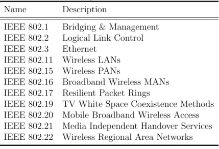
The IEEE is the world’s largest association of technical professionals with the aim in “Advancing Technology for Humanity”1 and is one of the leading in creation of standards. The IEEE 802 standards are intended to define the specifications for Local Area Net-work (LAN), Metropolitan Area NetNet-work (MAN). In the Table 2.1 is presented the groups in this family, where in this dissertation the main focus was the IEEE 802.15 standard.
Table 2.1: Family of IEEE 802 standards2.
Name Description
IEEE 802.1 Bridging & Management IEEE 802.2 Logical Link Control IEEE 802.3 Ethernet
IEEE 802.11 Wireless LANs IEEE 802.15 Wireless PANs
IEEE 802.16 Broadband Wireless MANs IEEE 802.17 Resilient Packet Rings
IEEE 802.19 TV White Space Coexistence Methods IEEE 802.20 Mobile Broadband Wireless Access IEEE 802.21 Media Independent Handover Services IEEE 802.22 Wireless Regional Area Networks
The IEEE 802.15 standard defines the categories presented in Table 2.2. The IEEE 802.15.4TM, focused on low rate wireless Personal Area Network (PAN), is the most rele-vant in the context of this dissertation. This standard will be presented in the following sub section as a basis for the MiWi and Zigbee RF4CE communications. It is also im-portant to refer that the IEEE standardized Bluetooth as IEEE 802.15.1 in 2002, but no longer maintains the standard [11]. Nowadays the Bluetooth is maintained by the Bluetooth Special Interest Group (SIG), that will be explained in a later section.
Table 2.2: Categories of IEEE 802.15 standard3.
Name Description
IEEE 802.15.1 WPAN IEEE 802.15.2 Coexistence IEEE 802.15.3 High Rate WPAN IEEE 802.15.4 Low Rate WPAN IEEE 802.15.5 Mesh Networking
IEEE 802.15.6 Wireless Body Area Networks IEEE 802.15.7 Visible Light Communication
1
http://www.ieee.org/about/tagline.html (visited on 29 August 2015) 2
From: https://standards.ieee.org/about/get/802/802.html (visited on 29 August 2015)
2.1. Family of IEEE 802 standards 9
2.1.1
IEEE Standard 802.15.4
TM- Low Rate WPAN
The IEEE 802.15.4TM is a standard that specifies the Physical and Medium Access Con-trol (MAC) layer taking into acount the Open Systems Interconnection (OSI) model as reference (Figure 2.1).
Data Link Physical Medium Access Control (MAC)
Physical Layer (PHY)
Network Transport Session Presentation Application OSI Model IEEE 802.15.4
Figure 2.1: IEEE 802.15.4TM stack.
The Physical layer (PHY) is in charge of RF communications and the IEEE 802.15.4TM specification defines the 868 MHz (Europe), 915 MHz (North Amer-ica) and 2.4 GHz Industrial, Scientific and Medical (ISM) (worldwide) license-free bands for operation with 1, 10 and 16 available channels and a theoretically data rate of 20, 40 and 250 kbps respectively. The 868 MHz and 915 MHz bands use the Binary Phase Shift Keying (BPSK) modulation, while the 2.4 GHz ISM band imple-ments the Offset Quadrature Phase-Shift Keying (O-QPSK) modulation [12], [13]. In order to improve the protection against interferences the Direct Sequence Spread Spectrum (DSSS) technique is used. The maximum packet size is 133 bytes that are divided in Preamble, start-of-frame delimiter, frame length and PHY service data unit as shown in Figure 2.2.
Octets: 4 1 1 <= 127
Field: Preamble start-of-frame delimiter frame length PHY service data unit
Figure 2.2: IEEE 802.15.4TM physical layer packet 1.
1 From:
http://standards.ieee.org/getieee802/download/802.15.4-2003.pdf (visited on 7 August 2015)
10 Chapter 2. Wireless interfaces for consumer electronics
Medium Access Control (MAC) handles all access to the physical layer and provides two services. The data service that provides the reception and transmission of data through physical layer and the management service that performs the network management [13].
IEEE Standard 802.15.4TM Network topologies
The IEEE Standard 802.15.4TMnetwork is composed by two types of devices, Full Function Device and Reduced Function Device. Depending on the role of the device in the network it can be classified as PAN Coordinator, Coordinator or End device [14].
Full Function Device (FFD) is a device with full implementation of the protocol and can act as coordinator or an end device.
Reduced Function Device (RFD) only the essential routines of the protocol were implemented and can only act as an end device.
PAN Coordinator is the principal controller of a PAN and needs to be a FFD.
Coordinator has the capability to extend the physical range of the network and needs to be a FFD.
End device can be a RFD or FFD, and normally are sensor nodes that provide infor-mation to the network.
These devices can operate in a Star or Peer to Peer (P2P) topology (Figure 2.3), where each can have only one PAN coordinator at a time. The main difference between the star and P2P topology is that in the star topology all devices can only communicate with the PAN Coordinator, while in the P2P they can only communicate between them [13],[15].
Figure 2.3: IEEE 802.15.4TM network topologies1.
1 From:
http://standards.ieee.org/getieee802/download/802.15.4-2003.pdf (visited on 7 August 2015)
2.1. Family of IEEE 802 standards 11
2.1.2
ZigBee
RRadio Frequency for Consumer Electronics
(RF4CE)
The ZigBee R RF4CE is a standard that defines the wireless communication network for
home entertainment equipment and remote control devices in CE domain to allow the multi-vendor interoperability between them. This standard also aims to be low cost, low latency and robust against interference. The Zigbee R RF4CE protocol stack (Figure
2.4), have the lower layers, PHY and MAC, defined by the IEEE 802.15.4TM standard and defines the network layer and the standard application profiles on top of these [16], [17], [18].
Data Link Physical Medium Access Control (MAC)
Physical Layer (PHY)
Network Transport Session Presentation Application OSI Model ZigBee RF4CE ZigBee Remote Control (ZRC) ZigBee Input Device (ZID)
Zigbee® RF4CE Network Not explicitly defined
Figure 2.4: ZigBee R RF4CE stack1.
The Physical Layer in the ZigBee R RF4CE operates in the 2.4GHz ISM band. This
band can be overcrowded and to avoid interferences, besides the use of DSSS technique defined by IEEE Standard 802.15.4TM, the ZigBee R RF4CE uses only the channels 15, 20
and 25, from the 16 channels availables. The channels 15 and 20, fall in the gaps between the 802.11 (Wi-Fi) channels 1, 6 and 11 [13], [19]. The ZigBee R
RF4CE Network Layer controls the communication between devices, providing the ability to discover and connect new devices with a secure communication, managing the channels (frequency agility) and provides power saving mechanisms. The network is implemented in a full LAN capability through multiple connections PAN in star topology with two node types [20].
Target device have the ability to create their own network.
Controller device can only join to the networks created by the target device.
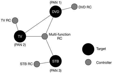
12 Chapter 2. Wireless interfaces for consumer electronics TV RC DVD RC STB RC Multi-function RC TV DVD STB (PAN 1) (PAN 2) (PAN 3) Controller Target
Figure 2.5: ZigBeeTM RF4CE topology1.
The topology is presented in Figure 2.5 and comprises three PANs created by each of the targets, three simple remote controllers that are connected to respective target and a multi-function remote controller that can connect with all three targets.
The ZigBee R RF4CE specification defines two profiles, located in the application layer
of the OSI model, that indicate how the devices communicate to ensure interoperability [18]. These profiles are the ZigBee R Remote Control and ZigBee R Input Device
de-scribed bellow, but also permits vendors to define their own proprietary profile, called manufacturer specific profiles.
ZigBee R Remote Control (ZRC) Profile are intended to define the commands
needed to control the CE devices. These commands are based on the High-Definition Multimedia Interface (HDMI) Consumer Electronics Control (CEC) but the ZigBee R Remote Control (ZRC) can query the CE device in order to get the
specific list of vendor commands supported by the device [16], [21].
ZigBee R Input Device (ZID) Profile enables the most recent controllers to control
the CE devices. This profile use the USB HID specification, that enables devices like touchpad, airmouse, keyboard, etc. to communicate with CE devices [16], [22].
1 From:
https://docs.zigbee.org/zigbee-docs/dcn/09/docs-09-5231-03-rmwg-understandi ng-zigbee-rf4ce.pdf (visited on 10 August 2015)
2.1. Family of IEEE 802 standards 13
2.1.3
Microchip Wireless Protocol (MiWi
TM) P2P
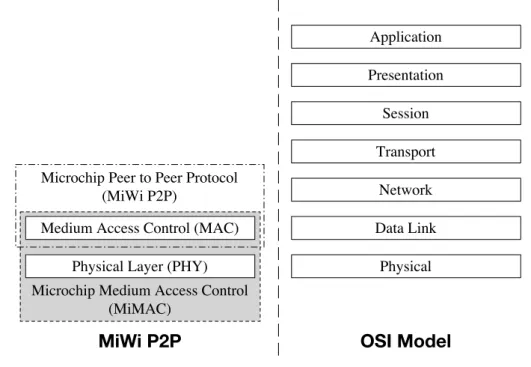
MiWiTM P2P is a Microchip Technology Inc. proprietary protocol with the same target for low power, low data rate and cost sensitive applications. As can be seen in Figure 2.6, this protocol stack uses the base of the IEEE Standard 802.15.4TM but with some modifications that correspond to MiMAC and MiWiTM P2P layers.
Microchip Medium Access Control (MiMAC)
Microchip Peer to Peer Protocol (MiWi P2P)
Data Link Physical Medium Access Control (MAC)
Physical Layer (PHY)
Network Transport Session Presentation Application OSI Model MiWi P2P
Figure 2.6: MiWiTM P2P stack1.
The MiMAC defines the MAC layer for communication protocols and transceivers supported by Microchip, removing the dependency between Microchip RF transceivers and the protocols stacks. The MiWiTM P2P is a direct wireless communication that only allows one hop and does not allow routing, which mean that all the devices needs to be in range with the PAN coordinator. Another major difference in the MiWiTM P2P protocol compared with IEEE 802.15.4TM is the handshaking process, that only needs two steps instead of seven, as can be seen in the Figure 2.7. These changes lead to a reduced complexity in the handshaking process. The MiWiTM P2P also uses an energy scan method for finding the channel with the least noise and can perform channel hopping, given that this protocol have frequency agility [12], [23].
1 Adapted from: MASTERs 2013 presentation - Advanced Wireless Networking (MiWiTM
14 Chapter 2. Wireless interfaces for consumer electronics
(a) IEEE 802.15.4TM Handshaking.
(b) MiWiTM P2P Handshaking.
Figure 2.7: Handshaking process1.
2.2
Bluetooth
RLow Energy (BLE)
The Bluetooth R wireless technology was intended to replace the wires for short range
communications. The BLE marketed as Bluetooth R Smart was introduced as part of the
Bluetooth Core Specification version 4.0, with the objective to reduce the power consump-tion of this technology. In the current year (2015), there are three types of devices, one with the already mentioned BLE technology, other with the classic Bluetooth R that is
the original version of the technology and the last one implements both technologies and is called Bluetooth R Smart Ready devices. As shown in Figure 2.8, Smart Ready devices
can act as a bridge between classic and BLE technologies, since these are not compatible with each other [24], [25].
The BLE protocol stack consists in two main sections (Host and Controller) as can be seen in Figure 2.9. The Controller comprises the lower layers of the stack that are hardware dependent, and normally is implemented as a small System on Chip (SoC) with
1
From: http://ww1.microchip.com/downloads/en/AppNotes/01204a.pdf (visited on 7 August 2015)
2.2. Bluetooth R Low Energy (BLE) 15
BR/EDR (classic Bluetooth) BR/EDR/LE (Dual-mode) BLE (Single-mode)
Figure 2.8: Compatibility between Bluetooth versions.
an integrated radio interface [26]. The Host is implemented as an application processor and is less hardware dependent, since the Host Controller Interface (HCI) makes the link between these two sections.
Figure 2.9: BLE stack1.
Physical layer (PHY) contains the analogue communication and modulation. This is performed by the BLE radio that uses 40 channels with 2 MHz bandwith each, and operates in the 2.4 GHz ISM band with Gaussian Frequency Shift Keying (GFSK) modulation. The channels at 2402, 2426 and 2480 MHz, represented in the Figure 2.10, are reserved for advertising. These frequencies were chosen to minimize the overlapping with IEEE 802.11 channels 1, 6 and 11, typically used by Wifi. The remaining 37 channels are used for bidirectional communication between connected devices. In order to avoid the interferences and wireless propagation issues, the Frequency Hopping Spread Spectrum (FHSS) mechanism is used , to select one channel for communications during a given time interval [24], [26].
Link Layer (LL) is responsible for general control of the link and transport, such as enabling of encryption on the logical Transport, coding/decoding of packets and the adjustment of the transmit power in the physical layer. This layer is the most time dependent layer, since it has the scheduler that grants the time for physical
16 Chapter 2. Wireless interfaces for consumer electronics
2402 MHz 2404 MHz 2424 MHz 2426 MHz 2428 MHz 2478 MHz 2480 MHz 37 0 1 2 … 8 9 10 38 11 12 13 … 34 35 36 39
Figure 2.10: Bluetooth Low Energy channels.
channels. It also contains the device manager, that controls the behaviour of the device like advertising, scanning, initiating, connected or in standby [27].
Host Controller Interface (HCI) is a bridge between Host and Controller. This in-terface can be implemented as software API or through a physical inin-terface such as Universal Asynchronous Receiver/Transmitter (UART), Serial Peripheral Inter-face (SPI), USB, etc [24].
Logical Link Control and Adaptation Protocol (L2CAP) provides data multi-plexing for the higher layers and data encapsulation to fit the maximum payload size of the L2CAP packets, that is 23 bytes [24].
Security Manager (SM) is intended to generate and manage the pairing keys in order to have a secure communication between devices. The BLE use Advanced Encryp-tion Standard (AES)-CCM cryptography with a block length of 128 bits [27]. The Attribute Protocol (ATT) allows to exchange attributes between devices. The
attribute is a small piece of data composed by the handle (address) with 16 bit length, the type that is Universally Unique IDentifier (UUID) and value [24], [27]. The Generic Attribute Profile (GATT) is an abstraction layer to be used by the
application to communicate with ATT service. Each device can expose generic attributes, that means, the device acts as GATT server, request attributes values from a server, as an GATT client or can be both simultaneously [24], [27].
The Generic Access Profile (GAP) provides an interface for the application to con-trol the behaviour of the device [27]. The device can act as broadcaster, observer, peripheral or central. The device that acts as broadcaster sends advertising events for the observer device to connect to it. Then the observer becomes the central device that is the master, and the broadcaster becomes the peripheral device that is the slave [28].
Chapter 3
The Universal Serial Bus (USB) in
Android
This chapter describes the technology used as base for the work developed in this disser-tation. In the first section, the USB 2.0 is approached in order to understand how this protocol establish the communication between two devices. This section provides details of the architecture, communication and the HID class of devices. This HID class allows to adapt the communication to match the needs for a specific device and the host will automatically recognize the functions provided by the device without the need for a spe-cific driver for each device. Also, the BLE and ZigBee R RF4CE, described in the chapter
2, implements the HID class unmodified from the USB. In the second section, the An-droid OS is presented, to give a better understanding of the software stack, applications, boot sequence, sensors and USB stack. This depper knowledge was needed to implement the java application, API and library for the sensors, that will be explained in the next chapters of this dissertation.
3.1
Universal Serial Bus (USB) 2.0
In this project, USB 2.0 devices are used for communication with an interface class called HID, which consists of devices that interact directly with the user. The keyboard, mouse and remote control are examples of these devices. To develop a USB HID device, it is necessary to know the USB architecture, communication protocol and available settings. These features are described in the next sub sections, followed by the characteristics of HID class.
18 Chapter 3. The Universal Serial Bus (USB) in Android
3.1.1
Recent advances of Universal Serial Bus (USB)
USB is the most used communication interface through cable to exchange data between a host and peripheral device in a short distance. The last advances in this technology introduced the USB 3.1 generation 2 and the USB Type-CTM [29]. The USB 3.1 is a dual bus that provides backward compatibility with the previous USB 2.0. One bus is exactly the same as the 2.0 and the other is the Enhanced SuperSpeed bus, as shown in Figure 3.1. As the name suggests this bus allows a higher speed communication between devices. These speeds are described in the Table 3.1 [30].
VUSB GND D+ D-SSRx+ SSRx-SSTx+ SSTx-USB 2.0 Enhanced SuperSpeed USB 3.X
Figure 3.1: USB 3.x Cable.
Table 3.1: USB speeds
USB 3.1 USB 2.0
Speed
Gen 1 (5 Gbps) low-speed (1.5 Mbps) Gen 2 (10 Gbps) full-speed (12 Mbps)
High-speed (480 Mbps)
The new USB Type-C is a connector ecosystem that arrives with the goal to be smaller, thinner, reversible and to allow more power through cables. This ecosystem enables the USB 3.1 and USB 2.0 given that implements both buses and allows the power up to 20 volts with 5 amperes [30]. Besides the new advances in technology, unless the highest speeds are needed, the USB 2.0 can be used given its backward compatibility. Nowadays (in 2015), the USB Type-CTM is being introduced in the new devices and despite the connector ecosystem is not in the scope of this dissertation, this option should be considered because offers a reversible connector, provides a bi-directional power and allows multiple modes, e.g. DisplayPort, HDMI, etc. To help understanding the work developed in this dissertation, the USB 2.0 and the Android OS architecture are described in the next sections.
3.1.2
Architecture
The USB is a industry-standard developed in the mid 90s, by a group of companies driven by the need to simplify the connection of peripherals with the personal computer [30]. The first version of USB was released in January 1996 and despite some limitations at the
3.1. Universal Serial Bus (USB) 2.0 19
time, it has been constantly evolving. Currently, it is an open architecture that allows suppliers to develop systems with devices able to communicate between them [31].
The USB architecture is based on the star topology divided by layers, where the HUB is the centre of each star (Figure 3.2) [32]. At the top it is located the host that is responsible for managing the communication, which is used a master/slave protocol to communicate with the devices. Next there are the connecting elements HUBs, needed to interconnect the host with devices, which are the last elements of this connection. The first HUB which is next to the host, is called “Root HUB”.
The maximum number of allowed connections in USB is 127 devices and 5 external HUBs (excluding the “Root HUB”) [33]. However, given the maximum bandwidth limit of the bus, the number of connected devices can be lower. The system can be separated into three main parts, the devices, the host and the interconnection between them.
Root HUB Host
HUB Device HUB
Device Device HUB Device
Device Device HUB Device HUB Layer 1 Layer 2 Layer 3 Layer 4 Layer 5 Layer 6 Layer 7 Device HUB Device HUB Device Device HUB
Figure 3.2: USB architecture1.
USB Device
A USB device can be referred as a physical or logical element that provides one or more functions to the host, i.e. at the lowest level the USB device refers to the hardware compo-nent and at higher level refers to the function performed by the USB device, respectively. The USB standard defines the function as the capabilities provided to the host, e.g. mice, keyboards, printers, etc. The devices that implement more than one function, are defined by the industry-standard as composite devices or compound devices (Figure 3.3) [33]. Compound devices are independent devices, or with different addresses that are
di-rectly embedded in the HUB (e.g., keyboard with expansion ports).
1 From: R. Regupathy, Bootstrap Yourself with Linux-USB Stack, 1st ed. Course Technology Cengage
20 Chapter 3. The Universal Serial Bus (USB) in Android
Composite devices do not use HUBs and have only one address, however, they are composed of multiple independent interfaces (e.g., mouse and keyboard interface).
Root HUB
Host
HUB Keyboard Mouse
Composite Device Compound Device
Address 1 Keyboard Mouse Address 1 Address 2 Root HUB Host Interface 1 Interface 2
Figure 3.3: Complex Devices.
Anyway, the devices can not initiate communication with the host, they can only answer and is not allowed direct communication between devices.
Host
In each system, there can only be one host per bus. The host should be responsible for detecting devices connected to the bus and manage the communications, ensuring that devices are able to send and receive data when needed. It is also responsible for providing power to devices that need it (i.e., devices connected to self powered HUBs do not need power from host) as well as try to save energy consumption when it is allowed, by suspending the connection with device.
Communication speeds
The USB industry-standard, originally defined two speeds for communication, low speed at 1.5 Mbps and full speed at 12 Mbps. Later in USB 2.0, with technological advances and increased processing capacity it was necessary to define a speed higher than the previous ones, having been set the new high speed as 480 Mbps [34]. The identification of the low and full speed communication is performed through the voltage level of the data lines.
At the beginning of a connection, the host data lines, D+ and D- are set to zero volts, since there is no pullup resistor to provide power (Figure 3.4). The USB device, needs to indicate its communication speed by placing a pullup resistor in one of the data lines. For the device to announce a full-speed communication with the host the pullup resistance must be placed on the line D+ (Figure 3.4(a)), in the case of low speed, this must be connected in line D- (Figure 3.4(b)). The pullup resistors change the voltage in data lines,
3.1. Universal Serial Bus (USB) 2.0 21
these changes are used by the host to identify a new device connected to the bus [35]. Some devices may contain this resistance internally, allowing to choose through firmware where it is connected (D+ or D-), otherwise it is needed externally [33].
Host D+ D-15 kΩ 15 kΩ Device D+ D-1.5 kΩ
(a) Full speed
Host D+ D-15 kΩ 15 kΩ Device D+ D-1.5 kΩ (b) Low speed
Figure 3.4: Configuration of speeds
The high speed communication is not set at the hardware level, however, a resistance in the data lines is required for the detection of a new device. When it intends to com-municate in high speed the device must support full speed, since the communication is initiated at this speed. At the beginning of the connection, the choice between these two speeds, high and full speed, is made when the device is restarted through the process of chirp handshake (Figure 3.5).
Figure 3.5: Chirp handshake1.
The USB device creates a chirp K (i.e., with the digital signal on line D+ as 0 and 1 in the D- line) which when detected by the HUB, if this has the ability to communicate at full speed, responds by alternating k and j chirps (Table I). The device must detect at least three pairs of alternating k and j chirps to assume that the hub is capable of communicating high speed. Once detected, the device should turn off the pullup resistor
1 From:
http://am.renesas.com/applications/key_technology/connectivity/usb/about_us b/usb2_0/usb2_5/index.jsp (visited on 11 August 2015)
22 Chapter 3. The Universal Serial Bus (USB) in Android
in D+ line to start the communication in high speed, if not detected, must continue in full speed mode and wait for the end of the reboot.
Table 3.2: Digital states of Chirp k and j in data lines.
D+
D-Chirp k High/Full speed 0 1
Low speed 1 0
Chirp J High/Full speed 1 0
Low speed 0 1
Interconnection
The USB interconnection is made through a cable with four conductors, two for data and two for power. The maximum cable length depends directly on the speed of communi-cation. However, given the maximum limit of the bandwidth of the bus, the number of connected devices can be lower. The main length constraint is due to the fact that there is a maximum propagation time for each packet transmitted over the bus. If this limit is exceeded, the packet is considered lost. The maximum length of cables for communica-tions at full speed is 5 meters and at low speed is 3 meters [34]. The connection can be extended up to 5 HUBs (excluding the root hub), so the limit is 30 meters at full speed and 18 meters at low speed.
3.1.3
Power supply
The USB has the ability to supply power to the devices connected to the host and the supply voltage is typically between 4.4-5.25V [34]. In this way there is no need for ad-ditional cables, which makes the devices lightweight and inexpensive, since they do not require an internal power source. However it is necessary to consider some limitations of the available power. There are three classes of consumption for bus powered devices: Low, High and self powered.
Low power devices, can sink up to ∼100 mA, while the high power devices can sink up to ∼500 mA. For higher consumption the device should be self powered and can sink up to 100 mA from the USB bus. The self powered HUB can supply 500 mA to each device, while if it is fed by USB bus can only provide 500 mA distributed by the devices [33].
3.1. Universal Serial Bus (USB) 2.0 23
3.1.4
Communication
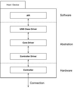
The communication between USB devices is divided in three main sections: software, abstraction of the protocol and hardware (Figure 3.6).
Host / Device
Controller Driver Core Driver USB Class Driver
API Controller Connection Hardware Abstration Software
Figure 3.6: USB protocol stack.
The software section is where the custom application is created to transmit/receive data. The Abstraction is divided into three layers: USB class driver, Core Driver and Controller Driver. USB Class Driver is composed by specific methods for different classes available in USB protocol (eg HID, video, audio). The Core Driver implements the USB protocol base functionality. The Controller Driver makes the link between the software and the hardware, so contains methods for reading and writing data in the physical channels. The next layer of the protocol stack is the hardware that enables connection between devices and the host.
The logical connection between the host and a terminal on the device is called a pipe (Figure 3.7). This terminal on the device, called the endpoint and are typically in pairs, respectively the input and output Endpoint. The Endpoint is seen as a buffer for the device, since it has no initiative to communicate, and thus requires a memory space to put the data until the host requests them. In the case of the host, which controls the data communication, the endpoints are viewed as a pipe and not as buffer. At the beginning of connection, the host starts the configuration of device, where the device indicates to the host the available endpoints, their respective characteristics and which interfaces are associated to it, except for the Endpoint 0. This endpoint is required on all devices, since it is exclusively used by the host to control and configure the device.
24 Chapter 3. The Universal Serial Bus (USB) in Android Host Device endpoint 0 endpoint 0 input Pipes
…
output endpoint 1 endpoint 1 input outputFigure 3.7: USB logical connections.
In USB communication there are two types of pipes, the Message pipe that is only used for device configuration, and the Stream pipe which serves to exchange data between device and host.
The mesage pipe has a format defined by the USB standard. This pipe is controlled by the host, and data can flow in both directions, but who determines the direction is the host, devices only can answer to requests. This supports only control transfers, which is directly related to the endpoint 0 [36].
The stream pipe contains no format, meaning that the device can send any kind of data throught the pipe. All the pipes have a predefined direction, input or output, and can be controlled by the device or host [36].
3.1.5
Types of transfers
The transfers follows a structure defined by the USB protocol. That is, the data to be transported through the stream or message pipes, are encapsulated according to the type of transfer to be made. The USB defines four different types of transfers, allowing to be chosen which is the most suitable for a particular communication. The types of transfers are the following [33]:
• Control Transfers: They aim to configure, give orders and request information about the current state of the device. Such transfers can only be made through the message pipe (Endpoint 0).
• Isochronous Transfers: Are designed for streaming data in real-time. This type of transfers guarantees the bandwidth, however, it is not made any error checking. • Interrupt Transfers: They are suitable for small amounts of data to be
3.1. Universal Serial Bus (USB) 2.0 25
allowed between data readings. If the device has no data to send, must return Negative-Acknowledgment (NAK).
• Bulk Transfers: This is intended to transfer a large volume of information and uses the maximum speed available for the transfer, but it is not guaranteed the moment in which is made. This type of transmission has the lower priority, however, it ensures that the transfer is made without errors.
Token
Packet Data Packet
Status Packet
Pipe Transfer
Transaction Transaction
Figure 3.8: USB transfers1.
The transfers are made of one or more transactions, and each one contain up to three packets (Figure 3.8) [37]. The first packet is the Token packet and contains information about the type of transaction and its direction, device address, and the endpoint. The second package, that is Data packet, consists in the data to be transferred and the last packet, Status packet, refers to the state of the transaction, that is, if it has been a successful transfer or not.
The data transmitted is encoded with the Non Return to Zero Inverted (NRZI) line code and the Least Significant Bit (LSB) is send first. To ensure frequent transitions, after successive six bits to ’1’, it is inserted the bit ’0’, this is known as bit stuffing [33]. All packets begin with a synchronization pattern to enable the receiver clock to be synchronized with the transmitter. This synchronization is considered as the start of packet, and the end of packet is identified by an delimiter pattern.
The complexity of the protocol requires its implementation in specific hardware to save computational resources from a micro-controller. This implementation is called Serial Interface Engine (SIE) and is located in the hardware layer of the protocol stack (Figure 3.6) [38].
1 From:
http://www.keil.com/pack/doc/mw/USB/html/_u_s_b__protocol.html (visited on 11 August 2015)
26 Chapter 3. The Universal Serial Bus (USB) in Android
3.1.6
Descriptors
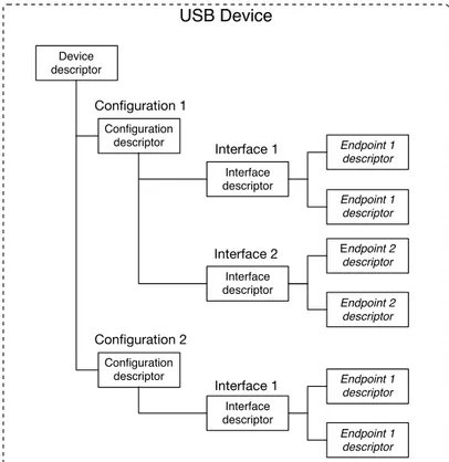
The descriptors of the USB devices consist in a data structure that allow to present properties of the device to the Host. During the detection of a new device, the host starts the enumeration process that relies on identifying the USB device and loading the correct driver. The device identification is performed trough the transfers of descriptors in a question and answer process. These descriptors are separated by several levels and are organized hierarchically (Figure 3.9) [35], [32].
The device descriptor at the top level describes the vendor, product, class, subclass, device protocol and how many settings exists. Each configuration contains a descriptor, which informs the host about the configuration number, the maximum consumption of the device, the features that are supported (e.g., Self-powered, remote activation, etc.) and the number of interfaces. The interfaces represent functions implemented by the device (e.g., Mouse, keyboard, etc.). The descriptor of the interface consists of the description of the class, subclass, protocol, and number of endpoints. The descriptor of endpoints contain the type of transfer, the maximum size of a packet and the address.
Devices USB HID constitute a specific class of an interface device is necessary in which additional descriptors, these are described in the following section.
USB Device Device descriptor Configuration descriptor Interface descriptor Interface descriptor Endpoint 1 descriptor Endpoint 1 descriptor Endpoint 2 descriptor Endpoint 2 descriptor Configuration descriptor Interface descriptor Endpoint 1 descriptor Endpoint 1 descriptor Configuration 1 Configuration 2 Interface 1 Interface 2 Interface 1
3.1. Universal Serial Bus (USB) 2.0 27
3.1.7
Human Interface Devices (HID)
The HID is a class of USB devices defined by a set of standards and communication protocols for devices that interact directly with humans. The USB protocol is used as a base, as well as enumeration process, whereas USB HID device uses the description to announce its operation to the host.
Through the descriptors, it is possible to unify the communication protocol while maintaining the freedom to define the data sent over the communication channel. As an example we have the mouse, which is an USB HID device and features a variety of buttons, as well as the cursor movement functionality on the computer screen. That is, through the descriptor we can set which data corresponds to the movement, and these are recognized by the operating system through the drivers. However more data can be sent, enabling the inclusion of additional features (e.g., ten buttons on a mouse).
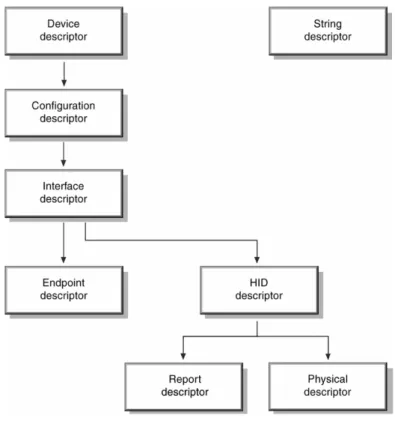
The descriptor of an USB HID consists in the descriptors of an USB device, plus the descriptor of the HID functionality, which in turn is divided in the device’s physical description and the report that is sent to the host.
Figure 3.10: USB HID Descriptors1.
28 Chapter 3. The Universal Serial Bus (USB) in Android
Report descriptor
The report descriptor of a device is a set of data that is exchanged between device and host, and there are three report types: Input Reports, Output Reports and Feature Reports. The descriptors sent by the host to the device are referred as Output Reports, while the descriptors from the device, that are answers to the requests from host, are referred as Input Reports. The Feature Report is optional and the data that can be manually read and/or written. The data in this report normally represent the state of the device and their configuration. The structure is defined by the descriptor of the USB HID device, which refer the details of the device and the data sent. The USB standard has a document with the details of all the features available for the USB HID report [39]. This report allows to assign meaning to data, so that the applications on the host side might show interest in a particular functionality without the need to know the place in where it came (e.g., X and Y of mouse).
The mouse report, usually contains the declaration of three buttons, wherein each button is represented by 1 bit. Through the report it is possible to define the meaning of each bit (e.g., the first bit is the left button, the second bit is the middle button, etc.). Through the meaning of the data for the predefined fields in the report, the developed application does not need to know the order of them. However, it is also possible to define a custom communication, where the fields do not are predetermined by the standard USB HID. Given this flexibility the report does not have a fixed size, since this varies according to the amount of data to send.
The report consists in a vector of bytes, that describes the data. These bytes usually are shown in two columns. The first column is the command and the second it is the value (Report 3.1).
Report 3.1: HID 1 0x05, 0x01, // USAGE_PAGE (Generic Desktop) 2 0x09, 0x02, // USAGE (Mouse)
3 0xa1, 0x01, // COLLECTION (Application) 4 0x09, 0x01, // USAGE (Pointer)
5 0xa1, 0x00, // COLLECTION (Physical) 6 0x09, 0x30, // USAGE (X) 7 0x09, 0x31, // USAGE (Y) 8 0x15, 0x81, // LOGICAL_MINIMUM (-127) 9 0x25, 0x7f, // LOGICAL_MAXIMUM (127) 10 0x75, 0x08, // REPORT_SIZE (8) 11 0x95, 0x02, // REPORT_COUNT (2) 12 0x81, 0x06, // INPUT (Data,Var,Rel)
3.2. Android Architecture 29
13 0xc0, // END_COLLECTION 14 0xc0 // END_COLLECTION
The command USAGE PAGE, selects the group of devices that will be used. The USAGE indicates which type of device that is inside of the previous group will be used in the definitions of the data.
In this case, the Report 3.1, begins by defining the table of generic desktop devices at line 1, and then indicates the device functionality as a mouse, on line 2. After we indicate the type of device, we can organize data into groups. In this case, we indicate that we have a collection of data that is used by applications (line 3). This collection uses data of the type pointer (line 4), that is, will be composed by data that corresponds directly to a screen axis. The pointer type collection, contains a collection of data that is directly represented geometrically, hence the collection of physical data type. This collection consists of the data X and Y (line 6 and 7). Each data can have a logical value between -127 and 127 (line 8 and 9), that are represented by 8 bits (line 10). On line 11, it is indicated how much data is reported, and in this case is 2 times the report size (8), representing X and Y values. Finally, is indicated that the data is an input on the host, and its value is variable and relative (line 12).
Physical descriptor
The physical description of the device, indicates which parts of the body should be used to handle the device. In the case of mouse, it is possible to describe which fingers are used to activate the buttons, as well as to distinguish between left-handed and right-handed. This description is not mandatory and in most devices, this type of information does not bring much use.
3.2
Android Architecture
Android was initially a company founded by Andy Rubin, Chris White, Nick Sears, and Rich Miner in October 2003, with focus in mobile devices with capabilities to adapt to information to the user. In August 2005 it was acquired by Google that began building partnerships with companies related to mobile ecosystem and in November 2007 has announced the Open Handset Alliance (OHA)1 [40], [41].
The first version of Android OS in Alpha phase was only available for OHA and Google members. Only on 5 November 2007, the Beta phase was available to the community and that date is popularly known as the Android birthday [41]. However, the first commercial
1
30 Chapter 3. The Universal Serial Bus (USB) in Android
version 1.0 was released only on 23 September 2008. Besides the two first versions (1.0 and 1.1) that do not have official names, all the other releases have tasty names that follow the Latin alphabet in the first letter. Since they only started in the third release, the first official name “cupcake” starts with the third letter in Latin alphabet [41], [42].
As Android was growing, the variety of devices that implements the OS was also growing. Nowadays Android OS is designed for phones, tablets, wearables, televisions and auto-mobiles, but given the fact that it is open-source, it allows to be implemented in a variety of other devices. It is worth noting that although the Android OS is claimed as open-source, the truth is that some times does not follow that spirit. The source code may take some time to become available and consumer devices contain several closed source software components that difficult the porting for other devices [41]. In order to better understand what is involved in the Android OS, this section presents an overview of the Android software stack, followed by the boot sequence and the USB and Sensors architecture in the following sub sections.
3.2.1
Software Stack
The Android Software Stack can be represented in five main layers (Figure 3.11), the Android Applications layer, Android Framework layer, Android Runtime layer, Hardware Abstraction Layer and Kernel layer. The lowest layer in the stack will connect directly with hardware in device.
Android Applications Layer is where stays all the applications that interacts directly with the user. This applications can be native (e.g, Phone, Settings, Contacts, etc.) or third party (e.g, Skype, Facebook, etc.).
Android Framework Layer is a set of libraries for Android Applications that provides the generic functionalities of the Android OS, in order to prevent the developer from having to code the most basic tasks, which would require an increased effort to develop the application (e.g., Telephony Manager, Location Manager, etc.). Android Runtime Layer comprises in a Virtual Machine (VM) and in core libraries in Java. The both upper layers are developed in Java and execute within the VM. The VM has the functionality of byte code interpreter.
Hardware Abstraction Layer is implemented in C programming language and allows the upper layers in stack to be independent of the hardware used. At the same level are the native core libraries in order to guide the device in handling different types of data (e.g., Open GL|ES, WebKit, libc, etc.).
Kernel layer of android consist of a Linux kernel adaptation that has the main purpose
3.2. Android Architecture 31
Figure 3.11: Android stack with details1.
of managing the input/output requests from the upper layers into hardware signals.
Android Applications
The Android applications are written in Java through the Android SDK tools that creates an Android application Package (APK). To create a more secure environment, all the applications that run on the Android OS, live in their own sandbox. This means that each application has its own VM and the code runs in isolation from the others applications, applying the principle of least privilege [41].
The applications can be build with four essential blocks, know as Activities, Services, Content providers and Broadcast receivers. An activity is responsible for managing the content displayed on the user’s screen. Normally the activity is considered the main of the application, thus it is only possible to have an activity to run at a time. The services are aimed at operations that take a long time and have to be initiated by other components. Since these can be performed in the background, it is possible to avoid freezing the user interface. The content provider is responsible for managing the access to a set of data, that is, provides the data from one application to the application that request it. Broadcast receivers are components that receives the announcements that exist on Android OS. This announcements can be originated by the system, like the screen rotation, or can be originated by the applications to inform all the other about some action [43].