Safety and Security System for House Boats
Indulal B
Head of Department in Electronics and Instrumentation in Government Polytechnic College, Cherthala, Kerala
Shimi S.L
Assistant Professor, Electrical Engineering Department, NITTTR Chandigarh
Abstract— The paper proposes a comprehensive automatic safety system for house boats using PIC Microcontroller, ZigBee Pro and LabVIEW. The critical parameters relevant to the safety of house boats are measured and monitored locally and remotely. The house boat can be monitored from a PC based remote control station. The location of respective house boat is available in the remote station as well as in the boat by GPS navigational system. The Graphical User Interface is designed using Lab VIEW.
Index Terms— House boats, PIC, ZigBee, LabVIEW, GPS
I. INTRODUCTION
India, especially Kerala, ‘God’s Own Country’, has immense scope in tourism, specifically ecotourism. One of the innovative and appealing aspects of ecotourism in Kerala is its house boats. The industry was thriving at a profitable level, but of late, frequent accidents that happened in house boats poised a serious challenge to this sector of tourism. Accidents major and minor occur frequently in house boat due to inadequate safety measures in house boats. Also the associated malpractices contributed a major share to the causes of accidents.
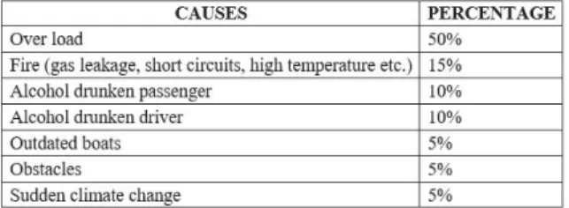
The main causes of accidents in house boats are due to overload, fire, alcohol drunken driver as well as passengers, obstacles, over speed, out dated house boats, short circuits etc. Table I given below shows a comparative analysis of various causes of accidents in house boats.
TABLE I: COMPARATIVE ANALYSIS OF VARIOUS ACCIDENTS’ CAUSES IN HOUSE BOAT
An automatic system can meet the requirements for the safety of houseboats as well as the security of tourists. The system can employ Global Position System (GPS) based fleet tracking unit, to identify the location of a houseboat and transmit the spatial or geographic information to a control monitoring station over the wireless communication network. The GPS system will also help the effective navigation of the houseboat. A remote station can be developed for monitoring and controlling various relevant parameters which cause the problems towards the safety and security of house boats as well as the tourists. If any abnormal conditions occur, the system can produce warning along with audible and visual alarms and send the details to the control station. From the Human Machine Interface (HMI) device, arranged in the control room, the houseboat can be guided.
Figure (1) shows the general block diagram of the proposed
Fig. 1. Proposed System Block diagram.
data are also available in the PC in the remote control room, of which GUI is designed using LabVIEW, situated in the remote control room, through the ZigBee communication network. Moreover any alerts from the weather forecasting centre can be communicated to respective house boats. GPS data are made available in the remote station as well as in the house boat for getting the exact location of house boat
A. Related Work
Automatic berthing system for ships and boats were developed based on Fuzzy Control System and GPS Navigational system [1], [2].The system provides necessary information regarding position, velocity, altitude, angular velocity and time, for the optimum berthing system. A control system model [3] was discussed for the analysis of a fully autonomous sail boat navigational system which allows to develop good routes while avoiding obstacles and environmental conditions such as winds, tides and currents.
A GPRS based system [4] for remote monitoring and online supervision of urban municipal swear gas was developed which includes modules for sensor, signal conditioning data transmission and supervision. An autopilot system [5] is designed for guiding the trajectory of a boat using charge coupled device camera. The measured angle is given to an Internal Model Control and hence the command signal is derived.
A Mechatronic system [6] for optimizing the operating conditions which maximizing the speed of a boat is designed and a model prediction controller is devised. A monitoring and command system [7] for the working boats’ operation is developed based on GPS and GIS engine technology.
Automatic traffic and safety management systems [8], [9] for ships were designed and developed with respect to the key aspects such as ships, navigational environment, people and safety management. Automatic systems 10], [11], [12], [13] for automobiles’ location, anti-theft and guidance were devised using GPS navigational systems, GSM module and embedded systems.
Arduino and Xbee based systems [14], [15] for environment monitoring, were presented for the energy management of factories where the environment is harsh and the scale is within the kilometers around. A smart sensor platform [16] was developed which includes sensor hardware interface and system integration framework.
System for obstacle detection based on LabVIEW and Laser measurement principle [17], was proposed for an intelligent vehicle. ZigBee based intelligent systems [18], [19], [20], [21], [22], [23] for different applications such as energy monitoring, lighting control and fire alarm control were presented. PIC based systems [24], [25], [26], [27], [28], [29] were developed for motor control, efficiency control of wireless sensor network, critical parameters’ control of server room, location control of vehicle, latitude and longitude control for hiking, climbing and sailing activities, and power factor correction.
An Intelligent Transport System [30] was proposed for practical vehicle speed estimation with a single multifunction magnetic sensor.
On completion of thorough review of available related literature, it is evident that a comprehensive automatic system, for the safety of house boat as well as security of tourists, is not yet even been designed. Only manual or semiautomatic systems are found, which are inefficient and ineffective in harsh and adverse conditions, generally prevalent in house boats. Fully automatic systems are available for ships, especially for their berthing, are not suitable for the application in house boats.
II. DESIGN SCHEME
A. Flow Chart
Fig. 2. Flow Chart of the Design Scheme.
The basic and most important step here is the selection of relevant sensors and actuators. Also the selection criteria for controller (PIC) and communication protocol (Xbee Pro) are again critically important. Moreover due importance has to be given to ensure the availability of data for all relevant parameters, which are critical for the safety of house boat as well as the security of tourists, at the input pins of PIC, after proper signal conditioning.
Next and foremost important step is to design the software for the PIC. During programming of the PIC, the interfacing and initialization of various peripheral modules such as LCD module, Xbee Pro, GPS module, relay module, Alarm circuit etc. are to be addressed. Also the effective communication of PIC with above mentioned modules has to be assured. The programming of the PIC, with desired features and requirements is achieved using MikroC.
After the programming of PIC, design the front end of the PC in the remote control room using LabVIEW. Ensure the proper interfacing of XBee with the PC. After this finalize the front end design. Finally test and evaluate the system by varying various input data and corresponding output data such as display, record and control. Also check the position of the house boat with GPS navigational system.
B. Hardware Design
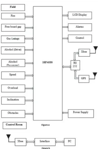
Fig. 3.Block diagram of Safety & Security System for house Boats.
B.1 The Field
Fig 3(a) shows the block diagram of the system in the field. As per the Table1(1), the critical parameters that adversely affect the safety of house boat are overload, obstacles, fire, alcohol consumed driver as well as passengers, inclination, level etc. These parameters are measured by proper transducers and the measured data are given to the PIC after proper signal conditioning. These data are compared with the set points by the PIC and the derived control signals are applied to the respective output units such as display unit, alarm unit, actuator or transmitter. A brief description of various sensors and output devices are given below.
B.1.1 Overload-Strain gauge with load cell
When a force is exerted on an object, the length of the object will change. The ratio of the change in length to the original length is called strain. A strain gage is a small section of very fine wire that changes electrical resistance when its dimensions are changed.
B.1.2 Obstacles- Laser measurement principles
B.1.4 Gas (LPG) Sensor-MQ2
The MQ series of gas sensors use a small heater inside with an electro-chemical sensor. They are sensitive for a range of gases and are used indoors at room temperature.
B.1.5 Alcohol Sensor- MQ3
When the alcohol molecules in the air meet the heated electrode, the ethanol burns into acetic acid and more current is produced.
B.1.6 Free-board gap (Level)-Float & Potentiometer
Free board gap is the level difference between the body surface and water surface. This is measured by an arrangement of Float and potentiometer assembly, set up on either side of the house boat. When the level changes, the float, attached to the moving contact of the potentiometer, moves and the output voltage changes. Taking the average of the voltages of the potentiometers on either side of the boat, the free board gap is obtained.
B.1.7 Inclination- Float & Potentiometer
Taking the difference between the voltages of the potentiometers on either side of the boat, the free inclination the boat is obtained.
B.1.8 Speed-Tachogenerator
The engine speed can be measured by Tachogenerator. However the actual speed of the boat is not the same as the engine speed since it is seriously depends on the nature of water such as its density, direction of water flow, other small obstacles etc. Hence actual speed can be measured by any positive displacement type flow meter.
If any abnormal conditions occurred, audible and visual warnings are provided. Also the required precautionary measures are taken. The various actions taken in different abnormalities are shown in Table II below.
TABLE II: PARAMETERS & CORRESPONDING ACTIONS.
@ Automatic cut of main supply, emergency standby supply in line, Auto start of fire extinguisher (actions depends on the intensity of fire)
#Engine cannot be started. * Engine cannot be started
^Entry of tourists to the upper deck is blocked.
All the warnings and indications in the field are also available in the remote control room. This is achieved by using RS 232 serial communication and XBee wireless communication network (up to 1500m). For large distance communication, GPRS or satellite communication can be used. Moreover the location of respective house boat is made available in the boat by GPS navigational system.
B.2 Control Room
B.3 Programming Flowchart for PIC
Fig. 4.Programing Flow chart for PIC.
@ Temperature, overload, speed, inclination, freeboard gap, Alcohol $ Temperature, overload, speed, Alcohol
# Left and right potentiometer readings * Gas leakage, smoke, Obstacle C. Software Design
Following steps are included in the software design for the control room
¾ Data from the Xbee transceiver, through the serial communication, which are in coded form, are read by preconfigured VISA READ.
¾ The data are decoded and given for further analyzing by LabVIEW. ¾ Display these data and warnings in the control room.
¾ The warnings, if any, are send to the boat, in the coded form through VISA WRITE and serial communication.
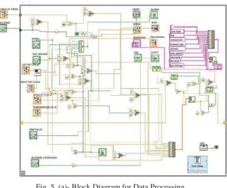
Fig. 5. (a)- Block Diagram for Data Processing.
Figure 5(b) shows the LabVIEW block diagram for the display of the processed data in the front panel of LabVIEW as shown in Figure (5).
Fig. 5. (b)- Block Diagram for Display of Processor Data.
III. CASE STUDY
Fig.6 shows the LabVIEW front panel, indicating an abnormal condition. Here an abnormal condition, fire, is simulated and corresponding audio and visual alarms as well as display is shown.
Fig. 6. LabVIEW Front Panel for Case Study.
IV. CONCLUSION
ACKNOWLEDGMENT
This work is carried out as a part of the project “SAFETY AND SECURITY SYSTEM FOR HOUSE BOATS”, for the award of ME Programme, from the department of Electrical Engineering, National Institute of Technical Teachers’ Training & Research (NITTTR), Chandigarh. We indebted to Dr. Lini Mathew, Head, Department of Electrical Engineering, NITTTR.
REFERENCES
[1] Vanecke, T.W “Fuzzy guidance controller for an autonomous boat”, IEEE Journal on Control Systems, Vol.17, No.2, pp. 43-51, 1997. [2] Warden, W.H., “A Control system model for Autonomous Sailboat Navigation”, IEEE Journal on Selected Areas in Communications,
Vol.2, pp. 944 - 947, 1991.
[3] Mami Ueno “A GPS-based system for precise shipping guidance and control”, Springer-Verlag, Journal of Marine Science and Technology, Vol.5, No.1 pp.9-15, Sept. 2000.
[4] Liu Peng ; Li Ping ; Liu An Cai ; Mao Yue Yi., “Design and Implementation of Safety Monitoring and Warning System of Toxic and Flammable Gas for Municipal Sewer Pipe Based on Nios-II and GPRS”, Information Technology and Artificial Intelligence Conference (ITAIC), 2011 6th IEEE Joint International, Vol.2, pp.394 - 397, 2011
[5] Sin-Der Lee ; Ching-Yaw Tzeng ; Young-ZehrKehr ; Chi-Chun Huang ; Chih-Kai Kang., “Autopilot System Based on Color Recognition Algorithm and Internal Model Control Scheme for Controlling Approaching Maneuvers of a Small Boat”, Oceanic Engineering, IEEE Journal of, Vol. 35, No. 2, pp.376 - 387 , April 2010.
[6] Fagiano, L. ; Milanese, M. ; Razza, V. ; Bonansone, M. “High-Altitude Wind Energy for Sustainable Marine Transportation”, IEEE Transactions on Intelligent Transportation Systems, Vol.13, No.2, pp.781 - 791, June 2012.
[7] Zuo Mingjiu ; Li Huaming ; Shu Chang., “Remote monitoring and commanding dispatch system of working boats based on C/S structure”, International Conference on Image Analysis and Signal Processing (IASP), pp.509 - 512, 2011.
[8] Ren Shaoyun, “Evaluation of Ship Traffic Control Safety Based on Analytic Hierarchy Process”, International Conference on Intelligent Computation Technology and Automation (ICICTA), pp.237 - 240, 2010.
[9] Yang Chun-Zhou ; Liu Hua-yu ; Zhan Xi-chen ; Zheng Hai-ping “Construction of Ship Safety Management Performance Evaluation System”,2010 International Conference on Management and Service Science (MASS)- Wuhan, pp. 1 - 7, 2010.
[10] Lita, I.; Cioc, I.B.; Visan, D.A.., “A New Approach of Automobile Localization System Using GPS and GSM/GPRS Transmission”, 29th International Spring Seminar on Electronics Technology, ISSE '06, St. Marienthal, Germany, pp. 115 - 119, 2006.
[11] Hu Jian-ming ; Li Jie ; Li Guang-Hui., “Automobile Anti-theft System Based on GSM and GPS Module”, Intelligent Networks and Intelligent Systems (ICINIS), 2012 Fifth International Conference on Intelligent Networks and Intelligent Systems, Tianjin, China pp.199 - 201 , 2012.
[12] Run, Ray-Shine; Jui-Cheng Yen; Cheng-Yu Tsai., “A Low Cost Implementation of GPS Guided Driverless Cars”, Conference on Industrial Electronics and Applications (ICIEA) - Taichung, Taiwan, pp.1610 - 1614, 2010.
[13] N. Lakshmi Kanthan, V. Babu, “Mcep based intelligent vehicle with multitask management”. International Conference on Information Communication and Embedded Systems (ICICES) - Chennai, pp.1144-1148.
[14] Wen-Tsai Sung ; Jui-Ho Chen ; Ching-Li Hsiao ; Jia-Syun Lin., “Multi-Sensors Data Fusion Based on Arduino Board and XBee Module Technology”, 2014 International Symposium on Computer, Consumer and Control (IS3C),Taichung, Taiwan pp.422-425, 2014. [15] Xia Liu ; Heping Chen ; Mengliu Wang ; Shanshan Chen., “An XBee-Pro Based Energy Monitoring System”, Telecommunication
Networks and Applications Conference (ATNAC), Australasian, pp.1 - 6, 2012.
[16] Cong Hui Huang; Yih Feng Su ; Yu Tang Su ; Wei Hao Su ; Jun Jie Chen ; Wei Jie Zhou., “Design and Application of ZigBee Wireless Techniques for an Intelligent House Lighting Control System” International Symposium on Computer, Consumer and Control (IS3C) – Taichung , pp.19 - 22, 2014.
[17] Dae-Man Han; Jae-Hyun Lim., “Smart home energy management system using IEEE 802.15.4 and ZigBee”, Consumer Electronics, IEEE Transactions on Consumer Electronics, Vol: 56, No: 3, pp.1403 - 1410, 2010.
[18] Ujwal Parmar. Sharanjeet Singh., “Comparative Study of ZigBee, Bluetooth and Wi-Fi Technology for Constructing Wireless Fire Alarm System”, International Journal of Advanced Research in Computer Science and Software Engineering, , Vol. 4, No.9, pp.893-897, September, 2014.
[19] Shuchao Ma ; Ming Zhu ; Lei Wang ; Lei Shu ; Suran Li ; Shumin Huang., “A Remote Monitoring System of IDC Room Based on ZigBee Wireless Sensor Networks”,. Eighth IEEE International Conference on Dependable, Autonomic and Secure Computing, Chengdu. pp.782 - 787, 2009.
[20] Mei-Sung Kang ; Yu-Lung Ke ; Jheng-Sheng Li., “Implementation of smart loading monitoring and control system with ZigBee wireless network” 6th IEEE Conference on Industrial Electronics and Applications (ICIEA), Beijing pp.907-912, 2011.
[21] Saravan V.; Arivoli. S.; Valarmathi, K, “ZigBee based monitoring and control of Melter process in sugar industry”, International Conference on Electronics and Communication Systems (ICECS) - Coimbatore pp.1 - 4, 2014.
[22] Madni, A.M., “Smart configurable wireless sensors and actuators for industrial monitoring and control”, 3rd International Symposium on Communications, Control and Signal Processing, Malta, pp. 447 - 448, 2008.
[23] Zeping Fang; Jianmin Duan, “Obstacle Detection for Intelligent Vehicle Based on LabVIEW and Laser Measurement System”, IEEE International Conference on Information and Automation, Yinchuan, pp. 202 - 206, Aug. 2013.
[29] Barsoum N., “Programming of PIC Micro-Controller for Power Factor Correction”, First Asia International Conference on Modelling & Simulation, Phyket, pp.19-25, 2007.