Dorit Chesler
Typology based Methodology
for In situ Testing of Masonry
Typology based Me
thodology for In situ T
es
ting of Masonr
Dorit Chesler
Czech university of Prague | 2014Typology based Methodology
for In situ Testing of Masonry
DECLARATION
Name: Dorit Chesler
Email: [email protected]
Title of the Msc Dissertation:
Typology based Methodology for In situ Testing of Masonry
Supervisor(s): Professor Luís F. Ramos, Professor Francisco Fernandes
Year: 2013-14
I hereby declare that all information in this document has been obtained and presented in accordance with academic rules and ethical conduct. I also declare that, as required by these rules and conduct, I have fully cited and referenced all material and results that are not original to this work.
I hereby declare that the MSc Consortium responsible for the Advanced Masters in Structural Analysis of Monuments and Historical Constructions is allowed to store and make available electronically the present MSc Dissertation.
University: University of Minho
Date: 15 July 2014
Signature:
ACKNOWLEDGEMENTS
First of all I would like to thank the Consortium for granting me sthe scholarship, which allowed and incuraged me to dedicate this year to my field of pasion.
I would like to thank my two supervisors, Professor Luís F. Ramos and Professor Francisco Fernandes, for their close guidance and their forthcoming approach in helping me fulfill my vision of this thesis. Professor Ramos, whose direction obliged me to pursue this topic to its maximum potential, and Professor Fernandes, which did not spare any effort to contribute his expertise to my work and education.
To my Engineer friends, Mafalda, Leidy, Michele, Giorgos, Josè, Andrès and Alessio, thank you. I could not have done it without you. Your help allowed me to exceed what I believed where my limits, and to excel in a field in which I was almost foreign. To my fellow Architects, Salma, Houcem and Lasha, my partners in crime, our mutual encouragement and partnership is something which will stay very close to my heart.
Finally, I want to thank Shay, my other half, for taking this year off and investing it in me and my education, and for walking hand in hand with me through all the challenges and difficulties that came along. This achievement is yours as much as it is mine.
ABSTRACT
Masonry and stone masonry in particular, has been the main building material throughout history in vast parts of the world. This extremely rich and variable material has a unique and not completely comprehendible nature, both in spatial-architectural terms and from the engineering point of view. The knowledge of material properties of historic masonry is often lacking, and furthermore, even when material properties are available, the constitutive laws coming from a good knowledge of the material are not enough. Many academic and practical efforts have been made offering different approaches to classify historic masonry, striving to unfold its complexity and to cast logic into its diagnostic approach.
The aim of this thesis is to contribute to the gained knowledge of historic masonry in Portugal and its diagnosis procedures. The main objective is to propose practical methodologies for diagnosis of historic masonry structures, corresponding to their typological characteristics. The study is based on the Portuguese architectural landscape, yet has global classifications, and thus can be useful for any diagnosis procedure of a historic masonry wall.
In order to develop such methodologies, information relating to historic masonry typologies in Portugal is gathered and classified. Consecutively, techniques for assessment of historic masonry are studied, and all information is integrated and utilized to develop typology oriented diagnosis procedures. These procedures are classified into rural, urban and military building types, and offer general guidelines for diagnosis of such structures, as well as in depth suggestions for specific diagnosis procedures. In addition, the recommended methodology is tested and validated in a diagnosis campaign carried out in the Guimarães Castle.
The development process illustrates that many advantages can be drawn to the field of historic heritage diagnosis by utilizing typological information. By considering both physical (geometry, morphology, etc.) and theoretical aspects of the typologies, different approaches to their diagnosis arouse. The validation process highlights the importance and value of precise pre-planning of the diagnosis procedure on one hand, but finds the necessity of flexibility in the on-site campaign on the other.
In order to employ this approach in practical campaigns, further study and classification must be attained. Yet hopefully this work can take us one step closer to decipher the comprehension of historic masonry.
RESUMO
A alvenaria e a alvenaria de pedra em particular têm sido o principal material de construção ao longo da história em vastas civilizações no mundo. Este material, extremamente rico e variável, tem natureza única e não completamente conhecida, tanto em termos espaciais e arquitetónicos, como do ponto de vista da engenharia. O conhecimento das propriedades da alvenaria histórica é muitas vezes inexistente. Muitas e diferentes abordagens têm surgido para classificar a alvenaria histórica, numa tentativa de compreender e reduzir a sua complexidade, a fim de se alcançar uma lógica nas abordagens de diagnóstico e de análise estrutural.
O objetivo da presente dissertação é contribuir para o conhecimento adquirido sobre a alvenaria histórica em Portugal e para os procedimentos mais corretos de diagnóstico estrutural. O objetivo principal é propor metodologias para a prática do diagnóstico de estruturas históricas. O presente estudo baseia-se no panorama arquitetónico Português, utilizado a sua classificação global para trabalho, podendo ser uma ferramenta útil para qualquer procedimento de diagnóstico de uma parede de alvenaria de uma construção histórica.
Para desenvolver as metodologias propostas, foram recolhidas e classificadas informações relativas às tipologias construtivas das alvenarias em Portugal. Consecutivamente, foram estudadas técnicas de inspeção. Toda a informação foi integrada e utilizada para o desenvolvimento de procedimentos de diagnóstico, orientados para cada tipologia. Os procedimentos foram desenvolvidos para três tipos de construções – rurais, urbanas e militares – e oferecem diretrizes gerais para o diagnóstico, bem como algumas sugestões para aprofundar cada diagnóstico específico. Além disso, a metodologia recomendada foi testada e validada numa campanha de diagnóstico realizada no Castelo de Guimarães.
As metodologias propostas permitiram concluir que, utilizando as informações tipológicas, muitas vantagens podem ser atraídas durante a fase de diagnóstico. Ao considerar tanto os dados físicos (geometria, morfologia, etc.) como os aspetos teóricos das tipologias, diferentes abordagens para o diagnóstico estrutural foram sugeridas para cada tipologia. O processo de validação da metodologia demonstrou, por um lado, a importância do valor do planeamento prévio das campanhas de inspeção, mas considerou, por outro, a necessidade de flexibilidade na utilização dos métodos de ensaio aquando dos trabalhos de campo.
Para que seja possível aplicar na prática estas abordagens, será necessário um estudo mais aprofundado das classificações e da metodologia proposta. No entanto, espera-se que este trabalho tenha contribuído para aumentar o conhecimento sobre a alvenaria histórica.
ריצקת
ב הינבה ןבא , םינושה היגוס לע , תא התוויה תטיש ירקיעה הינבה ת םלועה יבחרב הירוטסהה ךרואל . רמוחכ נב הי , תישומיש ברו תנווגמ ןבאה , םיידוחיי םינייפאמ תלעבו וניא םיתיעלש עבטו ןיטולחל ןבומ . תאז ןה םירשקהב םייללח -תיסדנהה טבמה תדוקנמ ןהו םיילכירדא . בורל , יקה עדיה הינבב רמוחכ ןבאה לש תויסדנהה היתונוכת לע םי רסח וניה תירוטסיה , ךכל רבעמו , הז ןיעמ עדי םייק רשאכ םג , םניא ונממ םיעבונה םייביטאוטיטסנוקה םיקוחה םיקפסמ . םיימדקא םירקחמ , םיבר םיישעמ תונויסינ םג ומכ , ןבאב תירוטסיה היינב גווסל תונוש תושיג םיעיצמ , תא טשפל הפיאשב םינושה היגוסל תומאתומ תוינוחבא תושיג רציילו התובכרומ . וז הדובע תרטמ , איה נל נבה םוחתב םיקה עדיה ףוגל םורתלו תוס ןבאב תירוטסיהה הי לגוטרופב ןוחבאה יכילהתו הלש . אמל םאתהב םיירוטסיה ןבא ינבמ ןוחבאל תוישעמ תויגולודותמ עיצהל הניה תירקיעה הנווכה םינייפ םיגולופיטה םהלש . ססובמ רקחמה ילכירדאה ףונה לע יוצמה לגוטרופב , תויה ךא ב ןחבנ אוהו םינייפאמ םיילבולג , לוכי ךילהת לכל שמשל יטסונגאיד אוה רשאב ןבאב תירוטסיה היינב לש . חתפל תנמ לע תוטיש ולא , וז הדובעב ןייומו ףסאנ עדימ יבחרב ןבאב תירוטסיהה היינבה ינייפאמב קסועה לגוטרופ . מב ליבק , ינבמ לש ןוחבאל תוירשפא תוקינכט ודמלנ ןבא םיירוטסה , ו עדימה תבוטל ללכות ףתושמה חותיפ היגולופיט יססובמ ןוחבא יכילהת . תוירוגטק שולש יפ לע םיגווסמ הלא םיכילהת תונוש היינב : היינב תירפכ , תיאבצו תינוריע . ולא תוצובקל סחיב םיעצומ ןוחבאל םיחנמ םיווק ללכנה תוריק תונושה תוירוגטקב םי , ו ןכ תויחנה םייתדוקנ ןוחבא יכילהתל . ףסונב , גולודותמה עצומה הי ת ךרעמב הפקותו הנחבנ תוקידב יטסונגאיד עצובש ה תוריק לע השעמל הכלה הריט לגוטרופב שארמיג ריעב . ךילהתל םיבר תונורתי רציימ יגולופיטה עדימב שומישה יכ שיחמה תויגולודותמה חותיפ ךילהת לש ינוחבאה ירוטסיהה תשרומה ת . ךותמ םייזיפה םיטקפסאל תוסחייתהה ( הירטמואג , ׳וכו היגולופרומ ) לש םייטרואיתהו תויגולופיטה , ולע רקחמה ןמ ןנוחבאל תונוש תושיג . ועצובש תוישעמה תוקידבה רתאב תובישח תא ושיגדה ונונכת הרורב היגולודותמ יפ לע ינוחבאה ךילהתה לש , תעצומש יפכ וז הדובעב . דגנמ , םג הלע ךלהמב תושימגב ךרוצה עוציב ןנכותמה ךרעמה רתאב . תוטישב שמתשהל תנמ לע וז הדובעב תועצומה ב םייטסונגאיד םיכילהת םיישעמ , שרדנ םי לש דומילו הניחב ךשמה םוחתה , םיפקת םיטקרפ םילכ ידכל ןתטירפו ןלולכש ךשמהו . תאז םע , ה רשפאת וז הדובע יכ הווקת ילוכ תומדקת ב דעצ ןטק ףסונ א ל רבע המשש הדיחה חונעפ ןבאב תירוטסיה היינב .TABLE OF CONTENTS
1.
Introduction
... 11.1 General ... 1
1.2 Objectives and Methodology ... 1
1.3 Thesis Outline ... 2
2.
Assessment of Historical Structures
... 32.1 Introduction ... 3
2.2 Investigation and Diagnosis ... 4
2.3 Non Destructive Testing (NDT) Methods ... 5
2.3.1Visual Inspection ... 5
2.3.2Geometrical Survey Techniques ... 5
2.3.33D Laser Scanning ... 5
2.3.4Sonic / Ultra-sonic Methods ... 6
2.3.5Impact Echo Reflection ... 8
2.3.6Infrared Thermography ... 9
2.3.7Ground Penetration Radar ... 10
2.3.8Tomographic Imaging ... 11
2.3.9Hardness Tests- Schmidt Hammer Rebound ... 11
2.4 Minor Destructive Testing (MDT) Methods ... 13
2.4.1Boroscopy ... 13
2.4.2Coring ... 13
2.4.3Micro Sampling Techniques ... 14
2.4.4Flat Jack ... 15
2.4.5Double Flat Jack ... 16
2.4.6Tube Jack ... 17
2.4.7Laboratory Moisture and Salt Content Tests ... 17
2.5 Conclusion ... 19
3.
MasonryTypologies in Portugal
... 233.1 Typology and Performance Assessment ... 23
3.2 Study of Masonry Typologies ... 24
3.3 Masonry Building Typologies ... 25
3.4 Rural Building Typologies ... 28
3.4.1Materials and Structural Techniques ... 28
3.4.2Architectural Characteristics ... 29
3.4.3Geometry and Morphology ... 31
3.4.4Loading ... 32
3.4.5Foundations ... 32
3.4.6Typical Damages ... 33
3.5 Urban Architectural Typologies... 34
3.5.1Materials and Structural Techniques ... 34
3.5.2Housing Typologies ... 35
3.5.4Foundations ... 41
3.5.5Churches, Monasteries and Urban Monuments... 41
3.6 Military Architectural Typologies ... 44
3.6.1Architectural Characteristics ... 44
3.6.2The Northern Fortressess ... 45
3.6.3The Midland Fortresses ... 47
3.6.4The Southern Fortresses ... 48
3.6.5Materials and building techniques ... 50
3.6.6Typical Damages ... 50
3.7 Comparison and Conclusion ... 52
3.7.1Former Studies- The Case of Italy ... 52
3.7.2The Case of Portugal ... 56
3.7.3Conclusion ... 59
4.
Methodology for Diagnosis of Rural Typologies
... 614.1 General Methodology Recommendations ... 61
4.1.1Questions of the Diagnosis ... 61
4.2 Inspection and Diagnosis ... 62
4.2.1Testing Compound ... 62
4.2.2Recommended Tests ... 63
4.2.3Implementation Example ... 65
4.3 Conclusions ... 66
5.
Methodology for Diagnosis of Urban Typologies
... 675.1 General Methodology Recommendations ... 67
5.1.1Questions of the Diagnosis ... 67
5.2 Damage Survey ... 69
5.2.1Testing Compound ... 69
5.2.2Recommended Tests ... 70
5.2.3Implementation Example ... 73
5.3 Mechanical Properties of the Masonry ... 74
5.3.1Testing Compound ... 74
5.3.2Recommended Tests ... 75
5.3.3Implementation Example ... 79
5.3.4Expected Results- Reference Values ... 80
5.4 Morphology and Geometry Detection ... 81
5.4.1Testing Compound ... 81
5.4.2Recommended Tests ... 82
5.4.3Implementation Example ... 84
6.2.2Recommended Tests ... 89 6.2.3Implementation Example ... 92 6.3 Damage Survey ... 93 6.3.1Testing Compound ... 93 6.3.2Recommended Tests ... 93 6.3.3Implementation Example ... 95
6.4 Mechanical Properties of the Masonry ... 96
6.4.1Testing Compound ... 96
6.4.2Recommended Tests ... 96
6.4.3Implementation Example ... 98
6.5 Conclusions ... 99
7.
Validation of the Methodology- Guimarães Castle
... 1017.1 Methodology Planning ... 101
7.2 Tested Locations ... 102
7.2.1Battlement Wall ... 103
7.2.2Central Tower South Wall ... 103
7.3 Battlement Wall Results ... 104
7.3.1Reference Stone Sonic Transmission ... 104
7.3.2Ground Penetration Radar ... 104
7.3.3Direct Sonic Transmission ... 106
7.3.4Impact Echo ... 107
7.3.5Correlation of Results ... 109
7.4 Tower Wall Results ... 111
7.4.1Ground Penetration Radar ... 111
7.4.2In-Direct Sonic Transmission ... 111
7.5 Discussion of the Results ... 113
7.6 Conclusions ... 113
8.
Conclusions
... 1158.1 Scientific Background ... 115
8.2 Diagnostic Methodology Development ... 115
8.3 Validation Process ... 116
8.4 Further works ... 116
9.
References
... 11710.
Annexes
... 12110.1 ANNEX 1- Implementation Tables for Diagnosis of Masonry Typologies ... 122
10.1.1Rural Typology - Double leaf Limestone ... 122
10.1.2Rural Typology - Single leaf Granite ... 123
10.1.3Rural Typology - Double leaf Schist ... 124
10.1.4Urban Typology - Single leaf Granite ... 125
10.1.5Urban Typology - Single leaf Limestone ... 128
10.1.7Military Typology - Triple leaf Limestone - Standing wall ... 134
10.1.8Military Typology - Single leaf Granite - Standing wall ... 137
10.2 ANNEX 2- Test Results of Morphology Survey in Guimarães Castle ... 140
10.2.1Direct Sonic Tests ... 140
10.2.2Indirect Sonic Tests ... 142
10.2.3Reference Stone- Direct & Indirect Sonic Tests ... 143
List of Figures
Figure 2. 1- Mechanical scanner in archeological survey in Egypt ... 6
Figure 2. 2- 3D Laser Scanning of Palac Potockich Radzyn Podlaski, Poland ... 6
Figure 2. 3- Submission of sonic velocity testing on a timber column ... 7
Figure 2. 4- Principles of Sonic Velocity in Solids ... 7
Figure 2. 5- Work principle of the Impact Echo Method ... 8
Figure 2. 6- Detection of interior metal bars via infrared thermography ... 9
Figure 2. 7-Inspected wall geometry ... 9
Figure 2. 8- Moisture detection of the inspected wall via infrared thermography ... 9
Figure 2. 9- GPR testing equipment ... 10
Figure 2. 10- Radargram showing voids and material change in concrete blocks ... 10
Figure 2. 11- Vertical and horizontal sonic tomography of a masonry wall ... 10
Figure 2. 12- Contour sonic tomography of a masonry wall ... 11
Figure 2. 13- Concrete compressive strength relation with rebound values. ... 12
Figure 2. 14- Boroscopy test execution and real-time graphic output ... 13
Figure 2. 15- The coring process, Figure 2. 16- Drilled core from a masonry wall ... 14
Figure 2. 17- Micro samples of mortar with wooden prosthesization ... 15
Figure 2. 18- Single flat jack inserted into cut ... 16
Figure 2. 19- Deformation stress diagram presenting results of single flat jack tests ... 16
Figure 2. 20- Double flat jack test configuration on a brick masonry wall ... 17
Figure 2. 21- Stress strain diagram presenting results of double flat jack tests ... 17
Figure 2. 22- tube jacks implicated on a masonry wall in laboratory at Minho University. ... 17
Figure 2. 23- Estimated relative costs of NDT/MDT ... 19
Figure 2. 24- Estimated relative execution complexity of NDT/MDT ... 20
Figure 3. 1- Geological map of Portugal ... 26
Figure 3. 2- Northern house built in granite ... 30
Figure 3. 3- Northern house built in mixed schist and granite ... 30
Figure 3. 4- Southern house built in limestone and earth ... 31
Figure 3. 5- Southern house built in limestone and brick ... 31
Figure 3. 6- Section of a double leaf schist masonry wall with connectors ... 31
Figure 3. 7- Elevation of a schist masonry wall ... 31
Figure 3. 8- Supporting granite elements in corners of schist constructions ... 32
Figure 3. 9- Supporting granite elements over openings ... 32
Figure 3. 10- Historical map of the Pombalina reconstruction plan of Lisbon. ... 36
Figure 3. 11- Aerial view of the Pombalina construction area. ... 36
Figure 3. 12- Schematic axonometric representation of a typical masonry basement. ... 36
Figure 3. 13- Schematic axonometric representation of a typical floor. ... 36
Figure 3. 14- Detail of a Pombalino system wall. ... 36
Figure 3. 15- Brick masonry between timber elements in Gaioleiro walls ... 38
Figure 3. 16- 'Tabique' exterior walls with no diagonal timber frame ... 38
Figure 3. 17- Schematic axonometric representation of a typical 19th century Porto House's façade.. 39
Figure 3. 18-Picture of a typical wooden beam pavement ... 39
Figure 3. 19- Connection between wooden beams and the lateral granite wall ... 39
Figure 3. 21- Clérigos complex in aerial view ... 42
Figure 3. 22- Plan of Clérigos complex ... 42
Figure 3. 23- Monastery of Jeronimos ... 43
Figure 3. 24- Cloister of the monastery ... 43
Figure 3. 25- Detail in Limestone ... 43
Figure 3. 26- Detail in Limestone ... 43
Figure 3. 27- Map of fortified sites in Portugal ... 44
Figure 3. 28- Figure of batters ... 44
Figure 3. 29- Figure of battlements ... 44
Figure 3. 30- Section scheme of a masonry earth wall ... 45
Figure 3. 31- Picture of retaining wall in Alentejo region. ... 45
Figure 3. 32- Masonry of Guimarães castle... 46
Figure 3. 33- Guimarães castle current condition ... 46
Figure 3. 34- Fort of Leca de Palmeira ... 47
Figure 3. 35- Aerial map of Bragandelo Fort ... 47
Figure 3. 36- Aerial view of the Almeida fortifications ... 47
Figure 3. 37- Picture of the Almeida fortifications... 47
Figure 3. 38- Aerial view of the Sacavem fortifications ... 48
Figure 3. 39- Typical walls of the Sacavem fortifications ... 48
Figure 3. 40- Walls of the Fort of Sagres ... 49
Figure 3. 41- Aerial view of the Fort of Sagres ... 49
Figure 3. 42- The fortress of Evoramonte in Alentejo. ... 49
Figure 3. 43- Section scheme of retaining wall in Estremoz. ... 50
Figure 3. 44- Elevation scheme of the base assembly of the fortress tower in Evaromonte. ... 50
Figure 3. 45- Elastic Modulus related to different building typologies ... 53
Figure 3. 46- Classes of masonries common in Italy... 54
Figure 3. 47- Good to poor quality connections in masonry ... 55
Figure 3. 48- Typical masonry cross sections ... 55
Figure 5. 1- Comparison between elastic modulus obtained from double flat jack tests and values of pulse sonic velocity measured in transparency in the same area in case of stonework. ... 78
Figure 7. 1- Estimated morphology from former study ... 101
Figure 7. 2- Locations of former and current campaigns ... 101
Figure 7. 3- Plan of Guimarães Castle, with marked locations of conducted campaigns... 102
Figure 7. 4- Apparent section of the wall ... 103
Figure 7. 5- General layout of the tested wall (GPR profiles in with, sonic tested area in red) ... 103
Figure 7. 6- Geometric characteristics of the inspected wall ... 103
Figure 7. 7- Sketch of tested reference stone ... 104
Figure 7. 13- Layout of testing position of impact echo testing, ... 108
Figure 7. 14- Plot of frequency signal, result of IE measurements in point 23 ... 108
Figure 7. 15- Horizontal plan of masonry section illustrating interior interfaces ... 109
Figure 7. 16- Horizontal plan of 4th course stone morphology estimation on top of radargram. ... 109
Figure 7. 17- Sonic transmission execution scheme ... 110
Figure 7. 18- Impact echo execution scheme ... 110
Figure 7. 19- Radargram from tower wall with 800 MHz antenna ... 111
Figure 7. 20- Radargram from tower wall with 500 MHz antenna ... 111
List of Tables
Table 2. 1- Compatibility of NDT/MDT to masonry typologies ... 21
Table 3. 1 - Characterization of common stones for construction in Portugal ... 25
Table 3. 2 - Classification of rural building techniques in stone ... 28
Table 3. 3 - Designation of the walls of old buildings... 34
Table 3. 4 - Summary of surveyed masonry structures relating to typology ... 56
Table 3. 5 - Summary of surveyed masonry structures related to stone type ... 57
Table 3. 6 - Common masonry typologies in Portugal ... 58
Table 4. 1 - Recommendations for damage and mechanical survey of rural masonry walls ... 62
Table 4. 2 – Practical tool for the inspection and diagnosis procedure of a rural masonry wall ... 65
Table 5. 1- Recommendations for damage survey of an urban masonry wall ... 69
Table 5. 2- Practical tool for damage diagnosis of a Porto single leaf granite urban wall ... 73
Table 5. 3- Recommendations for diagnosis of mechanical properties of an urban masonry wall ... 74
Table 5. 4- Practical tool for mechanical diagnosis of a Porto single leaf granite urban wall ... 79
Table 5. 5- Results of other studies performed in stone masonry walls ... 80
Table 5. 6- Recommendations for morphology detection of an urban masonry wall... 81
Table 5. 7- Practical tool for morphologic diagnosis of a Lisbon single leaf mixed masonry wall ... 84
Table 6. 1- Recommendations for geometric-morphologic survey of military wall ... 89
Table 6. 2- Practical tool for morphologic diagnosis procedure of a granite cut stone military wall .... 92
Table 6. 3- Recommendations for damage survey of a military masonry wall ... 93
Table 6. 4- Practical tool for damage diagnosis procedure of a limestone retaining military wall ... 95
Table 6. 5- Recommendations for diagnosis of mechanical properties of a military masonry wall ... 96
1.
INTRODUCTION
1.1 General
Masonry and stone masonry in particular, has been the main building material throughout history in vast parts of the world. This extremely rich and variable material has unique and inimitable qualities which are apparent in its visibility and through the spatial experience it grants its visitors. These qualities, and the methods to conserve and to reproduce them, have been an issue for study in many research campaigns in current times, as they rise over and over again in the field of historic structures.
From the engineering point of view, correspondingly, historic masonry has some inherent unknown variables and is in many cases an enigma waiting to be studied and solved. This "enigma" has been studied and addressed in many conservation practices in the past years, and is still being unfolded and better acquainted by researchers in small, gradual steps. The knowledge of material properties of historic masonry is often lacking, and furthermore, even when material properties are available, in the case of historic buildings the constitutive laws coming from a good knowledge of the material are not enough.
In Italy, a country rich in historic masonry architecture and its study, researchers offered the idea of classes of masonry buildings or masonry typologies which often correspond to different behavior of the structure (Binda, 2014). This thought offers a perspective to the study of masonry, which suggests qualitative classifications can contribute to the knowledge of this material. This perspective provides the basic idea, of which this thesis is nested upon, and which it aims to practice.
1.2 Objectives and Methodology
The aim of this thesis is to contribute to the gained knowledge of historic masonry and its diagnosis procedures. The main objective is to develop practical methodologies for diagnosis of historic masonry structures, corresponding to their typological characteristics. These methodologies will be based on the Portuguese architectural landscape, but as they have global classifications, can be useful for any diagnosis procedure of a historic masonry wall.
In order to develop such methodologies, information relating to historic masonry typologies in Portugal will be gathered and classified. In addition, masonry structural assessment methodologies
will be studied. Sequentially, all information will be utilized for the development of typology-based methodologies. Finally, a validation of the methodology will be carried out in a local case study.
1.3 Thesis Outline
This thesis is composed of eight chapters, including the current introduction.
The second chapter will address the study of structural assessment methodologies for masonry structures. Available non destructive and minor destructive techniques will be outlined, highlighting their capacities and limitations regarding application on masonry.
The third chapter will provide a partial overview of historic masonry structures in Portugal, based upon former studies and gathered information. The structures will be divided into three major groups: (a) the rural, (b) the urban and (c) the military type structure. Each typology will be described and examples will be given.
The fourth, fifth and sixth chapters will offer methodology for the inspection of rural, urban and military constructions. This, by utilizing conclusion gained from previous chapters, as well as additional relevant considerations. The methodologies will address different tasks of the diagnostic process as damage, mechanical, morphologic and geometric surveying.
The seventh chapter will present a validation attempt for the military developed methodology, in a testing campaign carried out in the Guimarães Castle. Results of the campaign will be given and post execution conclusions related to the methodology will be discussed.
The last chapter will argue the main realizations drawn from all previous chapters, as well as final conclusions of the work and recommendations for further studies.
2.
ASSESSMENT OF HISTORICAL STRUCTURES
This chapter will present the state of the art of the assessment of historic masonry walls. Different approaches to evaluation of mechanical properties of existing structures will be presented, particularly in the discipline of non-destructive and minor destructive tests, which are advantageous to heritage constructions. In addition, the scientific field of data fusion will be presented and its possible contribution to the diagnosis practice of historic masonry.
2.1 Introduction
Historical heritage can be found in architecture, in landscapes, in buildings of all types, from grand monuments to vernacular constructions. This historical heritage is living evidence and a tangible documentation of the life and traditions that are in the base of our society. Therefore, it must be preserved and safeguarded taking the most careful measures.
The task of preservation of historical structures is a very convoluted and delicate craft, and demands a body of knowledge from restorers, engineers and architects working in the field. Restoration works in the past 50 years in Europe and around the world have contributed to the accumulation of this body of knowledge. Several international committees, particular for the task of structural conservation have been established, as ISCARSAH committee of UNESCO, which published guidelines that were adopted by UNESO in 2003.
The guidelines present the main ideas as were specified in the Venice charter of 1964, and include: (i) Importance of context and environment,
(ii) Reversibility, (iii) Authenticity,
(iv) Importance of maintenance.
In light of these guidelines, all actions taken must be minimized only to guarantee safety and durability of the structure, with the least harm to heritage values. All planned actions must be demonstrated as indispensible, all techniques must be proven successive and all materials used for the work and their compatibility to the existing materials must be fully established.
These ideas and principles apply to all stages of the conservation process, from diagnosis to the chosen intervention. Therefore, the diagnosis stage must be planned very carefully and to be tailored to the specific needs and demands of the structure surveyed.
2.2 Investigation and Diagnosis
One of the most meticulous tasks of historical conservation in the initial phase of diagnosis of the state of the structure, its state of damage, mechanical properties, materials, structural stability, etc. The onsite investigation must be as non-destructive as possible and provide information with a high level of precision (Binda, 2006). This demands an articulated diagnosis procedure, consisting of different and complimentary techniques.
In the beginning of the 21-century a project called: "The ONSITEFORMASONRY project" was carried out, involving 15 international partners in the development and improvement of methodologies for the evaluation of structural and material properties. A major conclusion of the project was the necessity of careful preparation of the investigation, together with a precise description of the problem addressed. The operations of the diagnosis process should be carefully designed, bearing in mind that each and every investigation has its cost, and should be optimized to obtain the desired results (Binda, 2006).
Since conventional techniques for diagnosis in the field of civil engineering cannot be used in the case of historical structures due to their invasiveness, different approaches are continuously being developed and practiced. Non-destructive and minor destructive testing methods, often originated in other fields of engineering, are being applied and adapted for assessment of historical masonry structures. These techniques as, complementary tests, can be reliable useful on site, provided that reliable interpretation of the data is made (Binda et al, 2001). Results of these methods can sometimes be unsatisfactory due to inappropriate exploitation and adaptation of the techniques (McCahn et al, 2001). Thus, relying on previous studies, and using complimentary tests for a complete assessment is essential.
A key issue, as mentioned, is to undertake a systematic and holistic investigation, using not one, but several inspection methods, including visual inspection, historical research and the appropriate non-destructive, minor-destructive and destructive testing techniques.
2.3 Non Destructive Testing (NDT) Methods
Non-destructive tests should be generally preferred to answer questions of stability and performance avoiding invasive intervention and destruction of historical heritage. Non-destructive methods show satisfying results in different fields of investigation, as detection of voids and cracks, presence of moisture or salts, finding hidden element of the construction and others. The following pages will showcase several NDT techniques that have been proven to be applicable in historical structures.
2.3.1 Visual Inspection
A preliminary in-situ survey is useful in order to provide details on the geometry of the structure, the visible damages (cracks, out of plumb, material decay) and in order to identify the points where more accurate observations have to be concentrated. A visual inspection should be carried out as a first measure and as a base for planning further investigation and verbalizing the questions to be addressed in the process. Visual inspection should be done with some complimentary tools as a crack meter, a flashlight, a tape measure, and an orientation plan for marking the inspection results.
2.3.2 Geometrical Survey Techniques
The geometrical documentation of an historical structure is a very crucial step in its assessment and analysis. In fact, it is almost always a necessary first step in the investigation process, which allows the designer to conduct other, more in depth testing on its basis. A geometrical survey can be executed manually or by advanced systems. Manual techniques can be very tedious to perform. They include direct visual documentation, manual measurements by tape measures or by laser meters. The information gathered manually on site is later entered into digital software, to create a workable database.
2.3.3 3D Laser Scanning
The development of reliable and affordable methods for computed documenting historic structures is viable. 3D laser scanning is an exponent of the evolution of the non-contact techniques for built up structures survey and documentation. The information gained by detailed documentation is particularly important in structural modelling, allowing a practice on the base of the real geometry instead of on idealized geometry for getting more reliable results (Cheng, 2012).
A typical laser scanner can be subdivided into the following key units: laser ranging unit, optic mechanical scanner (as seen in Fig 2.1) and control and processing unit. Developed laser scanners can reach a very high accuracy and be activated from a distance to the examined structure. Recent studies and practices exploit the benefits of 3D laser survey for the production of damage maps and for identification of crack patterns and other surface deteriorations. An example of the method is presented in Fig 2.2.
Figure 2. 1- Mechanical scanner in archeological survey in Egypt. Figure 2. 2- 3D Laser Scanning of Palac Potockich Radzyn Podlaski, Poland.
(From: http://www.topcon.co.jp/,http://www.3deling.com/ )
Location of scanning unit should be planned and calculated to maximize available results. An integrate scanning work has to be planned for the whole object from several different scanner stations which can combine a set of order of multiple view (scanning worlds). For a 3D scan that supports 360 degrees field-of-view, the scanner has to move around the scanned objects to complete exterior scan views with registration targets.
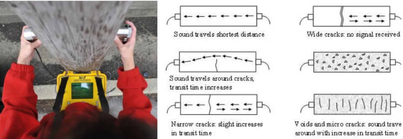
2.3.4 Sonic / Ultra-sonic Methods
Sonic / ultra-sonic testing methodology is based on the generation of sonic or ultra-sonic impulses at a chosen area of the structure. An elastic wave is generated by percussion, by an electrodynamics or by a pneumatic device (transmitter) and collected through a receiver, usually an accelerometer, which can be placed in various positions.
The elaboration of the data consists in measuring the time the impulse takes to cover the distance between the transmitter and the receiver. Appliance of the method and its principles can be seen in
(ii) to detect the presence of voids and flaws and to find crack and damage patterns,
(iii) to control the effectiveness of repair by injection technique and others which can change the physical characteristics of materials.
The method is based on the fundaments of wave propagation through solids. The velocity of a stress wave passing through a solid material is proportional to the density (ρ), dynamic modulus (E), and Poisson’s ratio (ν) of the material.
Resolution in terms of the smallest recognizable features is related to the dominant wave-length (as determined by the frequency) of the incident wave and also to the size of the tested element. As frequency increases the rate of waveform attenuation also increases, limiting the size of the wall section which can be investigated. The optimal frequency is chosen considering attenuation and resolution requirements to obtain a reasonable combination of the two limiting parameters.
In general it is preferable to use sonic pulse with an input of 3.5. kHz for inhomogeneous masonry.
Figure 2. 3- Submission of sonic velocity testing on a timber column, Figure 2. 4- Principles of Sonic Velocity in Solids
(From: http://www.ndtjames.com/,www.theconcreteportal.com/ )
Measurements obtained by the sonic and ultra sonic testing are qualitative and cannot be generalized globally. The pulse sonic velocity is characteristic of a specific masonry typology and it is impossible to generalize the values. The tests then have to be calibrated for the different types of masonry directly on site. Efforts have been made by researchers to correlate the sonic parameter to the mechanical characteristics of the material, but a fitting correlation has yet to be satisfied.
2.3.5 Impact Echo Reflection
Impact-Echo is a method for nondestructive evaluation of concrete and masonry, based on the use of impact-generated stress (sound) waves that propagate through the structure and are reflected by internal flaws and external surfaces.. It can be used to determine thickness or locate cracks, voids and other defects in masonry structures where the brick or block units are bonded together with mortar, and is not adversely affected by the presence of steel reinforcing bars.
The methods is activated by a short-duration mechanical impact, produced by tapping a small steel sphere against surface, which produces low-frequency stress waves (up to about 80 kHz) that propagate into the structure and are reflected by flaws and/or external surfaces. Multiple reflections of these waves within the structure excite local modes of vibration, and the resulting surface displacements are recorded by a transducer located adjacent to the impact. The piezoelectric crystal in the transducer produces a voltage proportional to displacement, and the resulting voltage-time signal (called a waveform) is digitized and transferred to the memory of a computer, where it is transformed mathematically into a spectrum of amplitude vs. frequency. Both the waveform and spectrum are plotted on the computer screen (Tikalsky, 2006). The dominant frequencies, which appear as peaks in the spectrum, are associated with multiple reflections of stress waves within the structure, or with flexural vibrations in thin or delaminated layers. The work principle can be seen schematically in Fig.2.5.
Figure 2. 5- Work principle of the Impact Echo Method
(From: http://www.impactecho.com/ )
To determine thickness or depth of a flaw, the wave speed C must be known. It can be measured by observing the travel time of a stress wave by direct sonic testing of known thickness (Schuller, 2003).
2.3.6 Infrared Thermography
Infrared thermography analysis is based on the thermal conductivity and emissivity (electromagnetic radiation) of materials. The method can be applied in passive or active radiation. The passive application analyses the radiation of a surface during thermal cycles due to natural phenomena of insulation and subsequent cooling. The active analysis, on the other hand, uses appliance of forced heating to the surfaces analysed (Drdacky et al, 2006).
A camera sensitive to infrared radiation collects the thermal energy, and the result is a thermo-graphic image in a coloured scale. Each tone corresponds to a temperature range. Usually the differences of temperatures are fractions of a degree. In the presence of moisture, the camera will find the coldest surface areas, where there is continuous evaporation. For masonry structures the method can be used for (Binda, 2005):
(i) Survey of cavities,
(ii) Detection of inclusions of different materials (Fig. 2.6), (iii) Detection of water and heating systems,
(iv) Moisture presence. (Figs. 2.7, 2.8)
One of the limitations of this method is that in the diagnosis of old masonries, thermo-vision allows analysis of only the most superficial layers, and cannot provide information regarding the inner sections of the walls. For plastered, frescoed or decorated walls, infrared thermography can be particularly applicable and efficient.
Figure 2. 6- Detection of interior metal bars via infrared thermography, Figure 2. 7-Inspected wall geometry, Figure 2. 8- Moisture detection of the inspected wall via infrared thermography
2.3.7 Ground Penetration Radar
Called also surface penetration radar and Geo-radar, the ground penetrating radar (GPR) uses reflections of wave energy to identify internal abnormalities in the wall thickness. Data is analysed in time domain, throughout a scanned section. The equipment for the test includes a radar control unit, an antenna, which transmits the waves as well as receives them and a data storage device (Fig. 2.9). The results of the scan are radargrams that are produced when the antenna passes along the surface of the object under investigation. Radargrams can be in colour or grayscale.
The method is taken from the field of geology and archeological surveys. When applied to masonry, the purposes of radar procedures can be (On Site for Masonry, 2005):
(i) to locate the position of large voids and inclusions of different materials, like steel, wood, etc. (Fig. 2.10);
(ii) to qualify the state of conservation or damage of the walls; (iii) to define the presence and the level of moisture;
(iv) to detect the morphology of the wall section in multiple leaf stone and brick masonry structures
Wave energy, as opposed to sonic or ultra-sonic waves can travel well through air spaces and can provide information beyond the first crack or hole. Measuring the dimensions and locations of inner elements of the walls can be calculated from the scans measuring the time range between the emission and the echo.
Limitations of this method lie in the high influence of moisture level in the masonry, which can alter results. Another disadvantage is the low readability of the results, scans are very complex and interpretation must be done by an expert.
2.3.8 Tomographic Imaging
Tomography is the practice of reconstructing a cross sectional image of an object from transmissions of energy through the object. Data from ultra-sonic, sonic or radar testing can be used as input for tomographic reconstruction algorithms, which provide a cross sectional representation of internal properties (Schuller, 2003).
The method was developed originally for the field of Geophysics, but has been adapted for the use of analysis of masonry and stone, and has shown reasonable approximations of size and extent of internal abnormalities. The tomographic analysis methods require a large amount of data acquisition in order to portray results of entire cross sections. Location and size of hidden cracks, voids and other deterioration processes can be tracked in the output data. Explanatory output is presented in Figures 2.11 and 2.12.
Figure 2. 11- Vertical and horizontal sonic tomography of a masonry wall, Figure 2. 12- Contour sonic tomography of a masonry wall
(From: www.ndt.net)
2.3.9 Hardness Tests- Schmidt Hammer Rebound
Rebound methods are founded in the base of the elastic theory. The rebound response of a material is a function of its dynamic modulus and its damping properties.
The "Schmidt Hammer" is an example of a test that correlates direct rebound results. The Schmidt rebound hammer is used to provide an indication of surface hardness. Identifying differences in hardness may indicate deficiencies in the material. With careful laboratory calibration, it is possible to relate rebound hardness to the elastic properties of the masonry and its compressive strength (Schuller, 2003).
Although not a highly accurate method, it can be a good instrument for comparing different results of a single material in several testing points. The test is conducted very easily and quickly, and can be affected by a variety of factors, as non-homogeneity of the tested material, element size, moisture, operator and others. Thus, it must be carried out in a large number of samples which will allow detecting any factors that may be affecting results. Specific type and orientation of the testing device (horizontal, vertical, diagonal) also has an effect on results, and must be considered when correlating rebound results to mechanical properties (Tikalsky, 2006).
Results should be converted from rebound values to strength by a corresponding table (for example, Fig. 2.13). As the device is designed for concrete these correlating tables are calibrated for concrete. When testing masonry, further calibration must be done.
Figure 2. 13- Concrete compressive strength relation with rebound values. (From:www.ndtjames.com)
2.4 Minor Destructive Testing (MDT) Methods
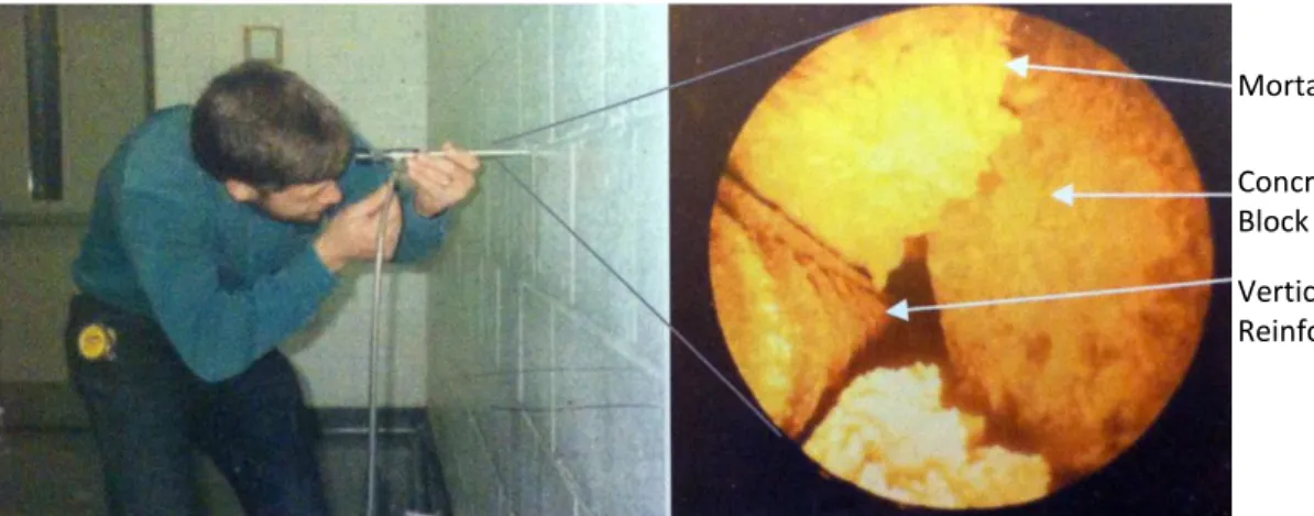
2.4.1 BoroscopyAlso mentioned as endoscopy, the boroscopy test allows the investigator to get an interior look of the section of the wall, with relatively minimal destruction. The procedure includes small diameter hole drilling done usually in the mortar joints, and insertion of a boroscope device. Boroscope devices incorporate fiber optics and an external light source to illuminate the internal space. Rigid and flexible boroscopes are available for use.
The technique can allow to (Schuller, 2003):
(i) observe identified abnormalities and defects,
(ii) observe internal wall components (flashing, ties, drainage cavities), (iii) provide information of section morphology.
Figure 2.14 shows the execution and the possible output of the boroscopy test.
Figure 2. 14- Boroscopy test execution and real-time graphic output
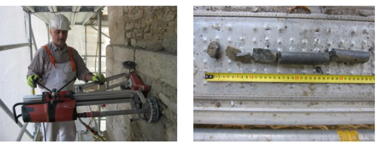
(Adapted from: Schuller, 2003) 2.4.2 Coring
Drilling of larger diameters may allow extracting cores of the masonry to be tested for compression bending and shear in the laboratory. This technique facilitates the ability to get site specific local results regarding the examined masonry mechanical properties, to reassure presence of voids and discontinuities and to learn of the inner morphology of the masonry wall.
Mortar Concrete Block Vertical Reinforcement
Figure 2. 15- The coring process, Figure 2. 16- Drilled core from a masonry wall
(From:www.expin.it)
Coring extraction is done by a drilling saw activated with water (Fig. 2.15). Thus, it can be somewhat harming for the masonry and this should be considered before application. As the operation is complex and involves both in situ and laboratory work, protocol must be followed to avoid confusion and misinterpretation of results. All cores shall be submitted to the laboratory for examination regardless of whether the core specimens failed during cutting operation. The laboratory shall report the location where each core was taken, the findings of their visual examination of each core, identify which cores were selected for shear testing and the results of the shear tests (Californian building code, 2010). A drilled core can be seen in Figure 2.16.
2.4.3 Micro Sampling Techniques
When working with complimentary NDT techniques, there is often a need for additional in-situ and laboratory testing for comparison of the obtained results with real mechanical measurements on specimens. As the investigated object is of heritage value, these tests cannot be conducted on other than small-micro samples. The complementary of micro sampling helps to evaluate the accuracy of the NDTs for the specific masonry and its damages.
The testing of non-standards samples was studied in the ONSITEFORMASONRY project, developing techniques to evaluate and test micro samples. Eventually, the research showed that testing mechanical properties in bending on non-standard mortar samples which were supplemented symmetrically on both ends with two “prostheses"(see Fig.2.17); the influence of prosthesization was negligible
Figure 2. 17- Micro samples of mortar with wooden prosthesization
(From: www.arcchip.cz )
Further study has shown that small samples from masonry materials are advantageously taken as drilled cores. Therefore, a portable testing frame has been designed and a first prototype has been produced. The device was designed as portable, durable and independent of external electricity supply, and can be used on site for immediate results.
2.4.4 Flat Jack
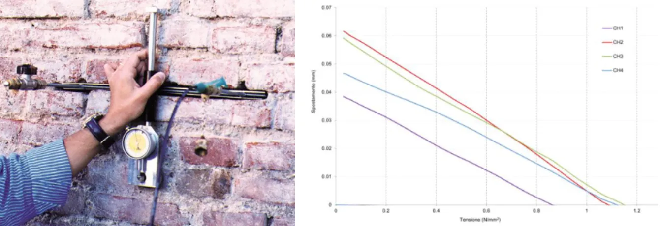
The flat jack test is a method that allows determining the local state of stress of the masonry. The determination is based on the stress relaxation caused by a cut perpendicular to the wall surface. The stress release is determined by the partial closing of the cutting, e.g. the distance between two points prior to cutting and following. The test is carried out by insertion of a cut perpendicular to the wall, and placing a thin jack inside it (see Fig. 2.18). Subsequently, pressure is applied through the jack and increased gradually, until obtaining the distance measured before cutting. Distances between the points of reference are measured before, during and after the sequence of the test.
The equilibrium relationship is the fundamental requirement for all the applications where the flat-jack are currently used (Binda, 2005):
Sf =KjKaPf
Where Sf is the calculated stress value, Pf is the flat-jack pressure, Ka is the slot/jack area constant
(<1), and Kj is the jack calibration constant.
Flat jack tests have given fairly good results and are a valid and preferable choice in the case of mechanical assessment of historical heritage. Alongside, the method has some disadvantages; it can be applied easily only on regular masonry. Irregular stone and joints placement cause difficulty in appliance; in multi leaf walls the results obtained refer solely to the exterior leaf. Internal leafs cannot
be tested; the method is almost inapplicable in low structures (lower than 2 floor) due to low stress levels.
Figure 2. 18- Single flat jack inserted into cut, Figure 2. 19- Deformation stress diagram presenting results of single flat jack tests
(From: www.controls-group.com, www.expin.it)
Another drawback may be the interpretation and elaboration of results. The reliable determination of the equilibrium pressure is a fundamental requirement for the test. In some cases, a significant amount of subjective judgment is necessary for interpretation. Displacement measurements can be questionable. Measurements carried out in the four chosen points of measurement will never give the same value and very seldom the original distance will be attained in all the four measuring points (Binda, 1999). Fig. 2.19 exemplifies the dissimilarity in results between the different testing points.
2.4.5 Double Flat Jack
Another possibility that the flat jack provides is the measurement of deformability. By making another cut, 40-50 cm below the first one, a sample of masonry is isolated and can be tested in uniaxial loading. The test configuration is shown in Fig. 2.20. Loading cycles are performed in increasing rates and deformations are measured. A deformability modulus of the masonry related to the stress levels can be obtained. Results from testing are presented as a stress strain diagram (see Fig. 2.21) from which the Elastic Modulus (E) of the masonry can be obtained by constitutive law.
Limitations of the technique relate to maximum stress levels; The applied stresses should all be lower than the measured stress of the single jack, in order to avoid crushing of the masonry; It is almost
Figure 2. 20- Double flat jack test configuration on a brick masonry wall, Figure 2. 21- Stress strain diagram presenting results of double flat jack tests
(From: www.expin.it)
2.4.6 Tube Jack
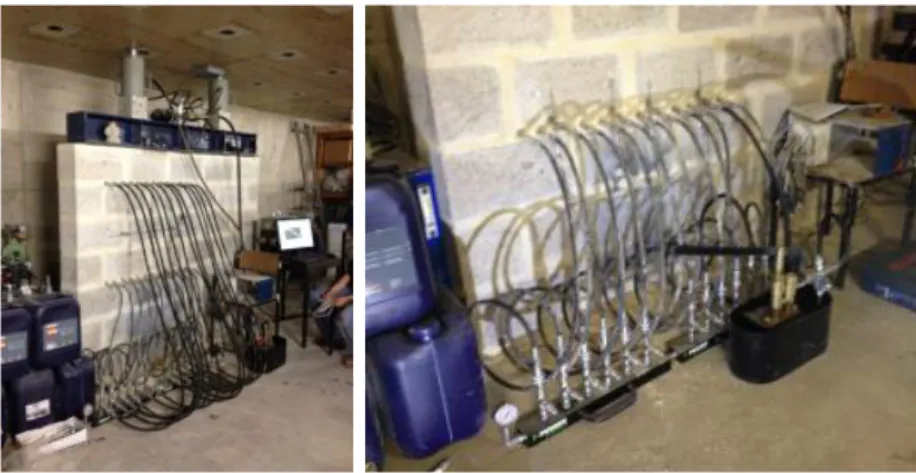
In order to overcome the limitations of applying a flat jack test on irregular masonry walls, the tube jack technique is now being developed at the University of Minho, Portugal. The tube jack test is carried out by insertion of a series of cylindrical hydraulic jacks into the inspected masonry wall, instead of the flat jack (presented in Fig. 2.22). With the fruition of this system, significant improvements in the in situ evaluation of the mechanical properties of masonry walls are expected.
Figure 2. 22- tube jacks implicated on a masonry wall in laboratory at Minho University.
2.4.7 Laboratory Moisture and Salt Content Tests
Several complimentary laboratory tests can be conducted to complete the diagnosis process. Moisture content and presence of salt anions can be detected in direct laboratory analysis from samples collected on site or by indirect in situ measurements.
(i) A chemical analysis can be performed with the goal of measuring the salt anions content on the material samples. The method includes crushing and grinding samples into powder, drying it to constant weight and later suspending it in distilled water. After the preparation of the sample it is tested for the presence of salt anions, conductivity and pH levels.
(ii) Numerous techniques are available for the detection of moisture content of stone and mortar. Among them are the Mobile Microwave Moisture measurement and the Gravimetric method. The Mobile Microwave Moisture measurement processes are dielectric measurement processes where the ratio of the dielectric constant (DC) of water and the material is determined. Even small quantities of water can be easily detected due to the great difference between these two values. The Gravimetric method, on the other hand, consists of determining the water content in a material by using the ratio of the mass of water present to the dry weight of the material.
Indirect methods, executed by moisture meters can determine moisture content by measuring the electric resistivity. This is a function of the moisture content and every factor that influences the electric conductivity of the materials as salts, composition, etc. Thus, the method is only applicable if all other parameters, besides moisture are invariable. There are no precise and direct calibration laws between resistivity and each material, so that the moisture content must be verified in laboratory by e.g. powder drilling technique. Thermohygrometer, that registers temperature, relative humidity, moisture content and dew in the air to determine the ambient conditions and its evolution, is necessary as supporting technique for the interpretation of data of moisture meters. (On site for masonry, 2005)
2.5 Conclusion
This chapter provides an introduction to the task of evaluation of masonry walls. Several non-destructive and minor non-destructive methods are nowadays proven to be efficient and are being used in the field of historical constructions worldwide. These tests provide the foundation for the design of diagnosis procedures as well as interventions. Some available tests provide direct, straightforward results and can be interpreted easily, but most techniques, however, require proper planning and execution. The operator experience is essential for appropriate employment of the test and for result analysis.
When planning an intervention for a historical monument the designer must consider numerous factors. The mentioned tests are available for his dispense but many other factors must be taken into consideration during the decision making process. These factors may regard the building under consideration, as the type of the building (private housing, public or civic, religious etc.), its size, uniqueness, and even level of significance to the cultural heritage. This must be considered as the available tests often have elevated costs, and complicated execution processes. In addition, several testing methods involve long term monitoring. Figures 2.23 and 2.24 present indicative relative costs and complexity of execution.
Figure 2. 23- Estimated relative costs of NDT/MDT
Figure 2. 24- Estimated relative execution complexity of NDT/MDT
(Adapted from: Harvey et al., 2010)
Factors may also regard the typology of the masonry under inspection, type of stone and mortar, assembling technique and its characteristics as number of leaves, regularity, connecting elements between leaves and others. This must be considered due to the fact that not every test is suitable for correct measuring and interpretation for the different masonry typologies. In other cases, some testing methods may be unnecessary for some typologies as they can only give us redundant information about them. Table 2.1 provides some information regarding capacity of the tests and their compatibility to some common typologies.
Table 2. 1- Compatibility of NDT/MDT to masonry typologies (Adapted from: On site from masonry, 2005)
NDT Masonry Typology MDT Masonry Typology
Sonic
+ in-depth, up to 100 cm analysis
- small stone units, irregular texture
Boroscopy + regular geometry
- dry stone
Coring - thin wall
Infrared + plastered sections
- in-depth analysis
Micro sampling
- mixed systems, as can only indicate on single element
GPR
+ in-depth, up to 150 cm analysis
- highly fragile plaster -thin walls
Flat Jack
+ regular geometry
- multi-leaf walls - irregular geometry
Hardness - mixed systems, as can only
indicate on single element Double FJ
+ regular geometry
- multi-leaf walls - irregular geometry
Tube Jack + regular and irregular geometry
- multi-leaf walls
Finally, factors must regard the question or problem under consideration. Different objectives relate to different courses of action. When studying damages the test selection will be different then when studying an un-given morphology. Often the typology will have an influence on the question of study. This and further in depth study of compatibility of typology and testing will be presented in the following chapters.
3.
MASONRY TYPOLOGIES IN PORTUGAL
This chapter will describe the role of typology in the mission of performance assessment of a historical structure. The current state of research of masonry typologies in Portugal will be presented and common masonry typologies in Portugal will be portrayed. Typologies will be divided into three categories related to the size of the structures and their purposes. These three categories will be elaborately characterized and studied in following chapters.
3.1 Typology and Performance Assessment
The structural performance of a masonry wall structure can be understood provided the following factors are known (Binda et al., 2001):
(i) Geometry,
(ii) Masonry texture (single or multiple leaf walls, connection between the leaves, joints empty or filled with mortar),
(iii) Physical, chemical and mechanical characteristics of the components (bricks, stones, mortar), (iv) Characteristics of masonry as a composite material.
A survey of these factors in masonry sections allows defining additional secondary influential parameters, such as: (a) the distribution of stones and mortar in percentage; (b) the ratio between the dimensions of the different leaves and that between the dimension of each leaf and the whole cross section; and (c) the dimension and distribution of voids in the cross section. These parameters, together with the chemical, physical and mechanical properties of the materials give the possibility to better describe the masonry and constitute a fundamental basis of any conservative intervention. Different typologies of the masonry exhibit different behavior under loading in different mechanical properties. Previous studies (as Binda, 2002 and others) have shown that a relation can be found between masonry morphology and geometry to its mechanical properties and structural behavior. Thus, surveying these typologies has a great prospective in achieving better assessments and higher accuracy in masonry testing.
3.2 Study of Masonry Typologies
In Portugal, little research has been conducted surveying types of stone masonry walls (geometric characterization, material and mechanical behavior). The available research is mainly local and does not give an overview of the whole country. Broader researches can be found regarding building typologies, but those do not address masonry typology per se. The available resources are seldom, particularly resources in English.
The most recent study has been done by Almeida (2013). The work focuses on one-leaf granite walls, common in the historical center of Porto and uses identification tools developed in earlier studies in Italy. Another available study is the work of Casella (2003) on the survey of building typologies in various regions of Portugal. The work contains references to general characteristics of the walls, including the geometry, the type of construction equipment, the construction process and the physical and mechanical properties of stone and mortar. Another two studies from 2004 should be mentioned; the work of Pagaimo, gathering information on limestone walls of the village Tentugal in the district of Coimbra. Twelve residential buildings were investigated - geometry and materials of walls were surveyed in elevation and cross-section in order to identify predominant patterns; and the work of Teixeira, dedicated to historic buildings of Porto.
On the contrary, very extensive studies on typologies of historic masonry walls were developed in Italy by Professors Binda and Mannoni in 2006. Their study initiated due to the significant number of buildings of stone masonry in Italy, suffering from recurrence of seismic activity in the Italian region. The aim of the study was evaluating the quality of the different masonry typologies for the estimation of the vulnerability of buildings and the definition of intervention procedures to be applied in a post-earthquake phases. The statistical character of results yielded valuable information about the characteristics of the masonry in Italy by region, and was gathered and stored in a database format. This study will be presented in detail in chapter 3.7 of this work.
When studying the following chapters, it should be considered that the scientific assessment of the Portuguese heritage sites still cannot be considered inclusive as in Italy. All conclusions and results obtained by this study will inevitably be partial or generalized, and will be based on former or similar studies or on few case studies that were examined within the scope of this thesis.
3.3 Masonry Building Typologies
Masonry construction was very widely practiced in historic Portugal, and the country is very rich with monuments and structures built with different construction techniques and using various types of stones. The kinds of stone traditionally used in the construction throughout the country are granite, shale (schist) and limestone. These can be used in different construction techniques, depending on local deposits and the tradition of knowledge. Basalts, due to their hardness and low workability, are less used (Casella, L, 2003). Characterization of the mentioned stones is listed in table 3.1:
Table 3. 1 - Characterization of common stones for construction in Portugal
(Adapted from: Casella, 2003) Origin Rock type Density Resistance
Kg/cm2
Workability Adhesion of the mortar
Igneous Granites 2.5 to 3.0 1500 to 2700 Variable Very good
Eruptive Basalt 2.8 to 3.3 3000 Difficult Bad
Melaphyre (Basalt)
2.8 to 3.0 1800 Variable Acceptable
Tufts 0.6 to 1.7 35 to 600 Variable, from very brittle to very abrasive
Acceptable
Sedimentary Calcareous 1.8 to 2.6 600 to 1500 Good Variable Loopholes 1.8 to 2.7 800 to 1700 Good, but
sometimes fragile
Variable
Metamorphic Sandstones 300 to 2700 Variable Variable Marbles 2.4 to 2.8 1100 to 1800 Good Good
Shale 2.5 to 3.0 800 to 1300 Variable Variable
As other European countries, the architecture in Portugal was greatly influenced by the cultural currents that have characterized the various eras of its history, leading to a highly enriched architectural prospect. The diversity of shapes and materials in traditional Portuguese architecture is related to many factors, including geography, economy, social issues, history and culture, and the type of needs and available goods in each region. For example, buildings in granite dominate the northern region of the country, Schist constructions are principal in the central region and limestone is found in Southern region constructions (Almeida, 2013). Figure 3.1 shows a geological map of Portugal from 1994, which clearly presents the governing rocks of the different regions.
Figure 3. 1- Geological Map of Portugal
(Adapted from: Pimentel, 1994)
As can be seen above, limestone can be found namely in the south and in the Lisbon area, while the north is predominated by mostly granites and shales. Shales can also be found in other regions and are quite widespread.