Effect of Dilution on the Microstructure and Properties of CoCrMoSi alloy Coatings
Processed on High-Carbon Substrate
Karin Grafa, Ulrich Tetzlaffb, Gelson Biscaia de Souzac, Adriano Scheida,*
Received: July 16, 2018; Revised: October 08, 2018; Accepted: October 25, 2018
The Laves phase reinforced CoCrMoSi alloy system has emerged as a candidate material to protect the surface of components to withstand harsh environments under wear and/or corrosion. However, previous reports have raised some concerns and restricted a wider selection of iron-based substrates to be coated, especially limiting the carbon content. This work aims to outline the Laves - Carbides
phases in the microstructure and its effect on the properties of T400 alloy deposited on GGG40 ductile
iron. Dilution of 26 % ensured Laves formation either as primary or secondary, due to high-silicon
substrate selected. Departing from 41 % dilution, the alloy changed to a completely carbide strengthened
system. Therefore, for the lowest dilution the coatings hardness is dictated by Laves phase whereas,
for higher ones, carbides are the most influent phases.
Keywords: CoCrMoSi Alloy, Microstructure, Coatings, High-Carbon Substrate.
*e-mail: [email protected].
1. Introduction
The demand for extending the useful life of mechanical components has been a challenge for engineers, especially when the operating condition involves wear, corrosion, or both simultaneously. Hardfacing presents itself as a good
alternative to protect the surface for specific applications,
since it addresses particular issues related to wear mechanisms such as adhesion or abrasion, which are often associated with corrosive media 1. Surface wear resistance may be substantially improved by depositing a wear resistant material through a welding process 2. Therefore, the selected feeding material, substrate and processing parameters emerge as decisive on the microstructure and hardness of the resulting coating and, thus, its wear behavior 1.
As a welding technique to produce hard coatings, Plasma Transferred Arc with powder feeder (PTA-P) has being widely employed. The powder feeding material produces
refining microstructures and also enables a modifiable
chemical composition of the coatings. PTA-P has many advantages, such as metallurgical bonding, dilution control, low penetration, reduced melting pool oscillations and no
spray, good control of the geometry and surface finishing
of the processed layers 3,4.
The most broadly adopted surfacing alloys are high-carbon/chromium iron-based alloys, chromium-graphite mixtures, iron-based alloys enriched by niobium, titanium, molybdenum and/or boron and nickel and cobalt-based
alloys. The latter are recognized for their excellent wear and corrosion properties, high strength and ability to retain hardness at high temperatures 1.
The CoCrMoSi alloy system exhibits excellent wear resistance that relies on a large percentage of the Laves hard intermetallic phase (CoMoSi and/or Co3Mo2Si). In this system, Laves is usually a primary phase dispersed in a lamellar eutectic structure that comprises cobalt solid solution (Co-SS) and secondary Laves phase lamellas. This typical microstructure is developed in the commercially known Tribaloys, as T800
and T400 5-10. It should be noted that T400 alloy was designed with a lower amount of chromium and silicon compared to T800 for higher ductility and toughness through reducing primary Laves phase formation up to 50 % 7-9.
As Tavakoli et al.7 suggest, an advantage of tribaloy alloys over carbide-reinforced Co-based ones is that the Laves phase is softer (hardness about half) than the carbides, the latter wearing away sometimes a mating surface. For this reason, the carbon content in tribaloy alloys is kept low to prevent carbides forming in preference to the Laves phase 7. It can also justify the fact that microstructure and mechanical properties of CoCrMoSi alloys have been extensively studied as coatings on low-Carbon AISI 316L stainless steel substrate 11-16. As a result, however, there is limited information about processing of these complex alloys on low-cost high-carbon content substrates such as cast irons (Fe-C-Si alloys).
Many studies have being carried out to improve corrosion and wear resistance selecting Ni-based alloys, 17-20, TiC-W-Cr alloying 21, and in situ precipitation of TiC22on gray cast
aDepartamento de Engenharia Mecânica - DEMEC, Universidade Federal do Paraná, Av. Cel.
Francisco H. dos Santos, 210, Curitiba, PR, Brasil
bDepartment of Materials Engineering, Technische Hochschule Ingolstadt - THI, Esplanade, 10,
Ingolstadt, Germany
cDepartamento de Física, Universidade Estadual de Ponta Grossa - UEPG, Av. Gen. Carlos Cavalcanti,
irons. Despite showing the effect of iron additions on the Tribaloys T400 and T800 microstructure and properties 23-25,
there is an evident gap concerning the effect of processing
CoCrMoSi alloys coatings on Fe-C-Si alloy substrates.
Hence, the aim of this investigation is to evaluate the effect
of simultaneous introduction of iron, carbon and silicon (due to welding dilution) on the microstructure and properties of
the Co base T400 alloy coatings processed by PTA on high-carbon content GGG40 ductile Iron. Emphasis was given to
outline the expected phase competition in the microstructure
(Laves / carbides) and its effect on the properties of coatings.
2. Materials and Methods
CoMoCrSi alloy, commercially known as Tribaloy T400,
with particle size ranging between 50 - 150 µm, was deposited
on ductile iron (GGG40) substrate, as shown in Table 1.
In this work, the main objective was to investigate the
effect of dilution with the substrate on the microstructure and
properties of the coatings. Thus, to promote distinct dilution, coatings were prepared by PTA-P as single beads with four distinct deposition currents: 120, 150, 180 and 200 A. The procedure is in agreement with previous experience and results presented in the literature for such an approach 11,13,24,26-28. Table 2 shows the main deposition parameters utilized.
Single bead specimens were cut on a transversal cross section for metallographic analysis according to standard procedures, which involved grinding and polishing. Coatings were also characterized according to their bead geometry (height, width and wettability), and dilution was assessed by areas method 24,26-28.
X-ray diffraction (XRD) analysis was carried out on the
top surface of coatings with KαCo radiation ranging from 30
to 120º for phase identification. Microstructure was analyzed by scanning electron microscopy (SEM) on the transversal
cross section of the deposits.
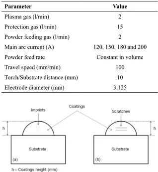
The effect of dilution on coatings mechanical properties
was assessed by hardness Rockwell C. Further analysis of the microstructure phases hardness involved instrumented indentation method (MTS Nanoindenter XP) carried out in
110 different sites with cycling loads of 20 mN. Moreover,
coatings were scratched under 100 mN constant load. The indentation imprints and scratches width produced with a Berkovich-type diamond tip in the specimens transverse cross-section were examined through backscattered electrons
(BSE) in a SEM (TESCAN™), as seen in Fig. 1.
3. Results
3.1 Coatings dilution and geometry
As expected, single bead coatings of 100 mm in length revealed no welding defects such as cracks, undercut, under
fill or porosities. As the current intensity increased along
width and wettability, the height of the layers decreased. It was observed that the higher the heat input (higher current intensity) was, the higher was dilution, as shown in Table 3.
3.2 Microstructure description
XRD analysis indicated predominance of cobalt solid solution (Co-SS) and Laves phase (CoMoSi and Co3Mo2Si) in the microstructure for coatings processed with 120 A (26 % dilution). As the deposition current increases (dilution
between 41 and 50%), Laves was completely suppressed
and carbides formed preferentially to the Laves phase, as
can be seen in Fig. 2. Table 4 presents a summary of the different phases.
Fig. 3a-d shows a general view of the microstructure
observed with SEM in the backscattered electrons mode (BSE) for the specimens. As the deposition current increases,
it is clear that lighter phase (primary) gradually decreases.
Table 1. Chemical composition of the materials studied (weight percent)
Alloy Fe Co Mo Cr Si C
CoCrMoSi
(Tribaloy T400) 0.4 Bal. 29.1 8.8 2.4 <0.1
Substrate Fe Si C Mn Pmax. Smax.
Ductile Iron
(GGG40) Bal. 2.8 3.9 0.2 0.04 0.02
Table 2. Processing parameters
Parameter Value
Plasma gas (l/min) 2
Protection gas (l/min) 15
Powder feeding gas (l/min) 2
Main arc current (A) 120, 150, 180 and 200
Powder feed rate Constant in volume
Travel speed (mm/min) 100
Torch/Substrate distance (mm) 10
Electrode diameter (mm) 3.125
Table 3. Dilution and geometry of single bead coatings
Characteristic Deposition Current (A)
120 150 180 200
Dilution (%) 26 41 44 50
Height (mm) 4.5 4.0 3.0 2.5
Width (mm) 9.5 13.0 14.0 17.0
Wettability
Angle (θ) 56 44 40 30
Figure 2. XRD diffractograms for the conditions evaluated.
Table 4. Summary of the main phases Deposition
Current (A)
Main Phases
Primary Phases Eutectic
120 CoMoSi / Co3Mo2Si + Co6Mo6C / Co6Mo6C2
Co-SS + CoMoSi / Co3Mo2Si
150 Co
6Mo6C / Co6Mo6C2
Co-SS + Co6Mo6C / Co6Mo6C2
180 Co
6Mo6C / Co6Mo6C2
Co-SS + Co6Mo6C / Co6Mo6C2
200 No primary phase Fe-SS + Co6Mo6C / Co6Mo6C2
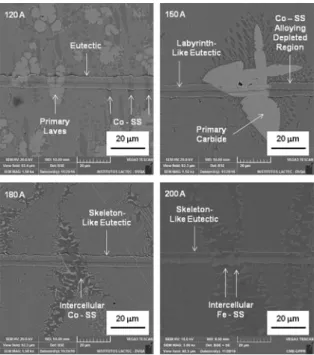
Figs. 4- 7show the detailed microstructure of the coatings. Fig. 4a-b shows that the lighter phase is comprised of primary
Laves phase (CoMoSi / Co3Mo2Si) and primary edged carbide. Moreover, the microstructure showed a lamellar eutectic structure with Co-SS and secondary Laves phase. It is important to highlight that surrounding the primary phases; the composition was depleted in molybdenum inducing a local
hypoeutectic solidification with Co-SS dendrites (Fig. 4b).
Figure 3. General view of the coatings microstructure.
Figure 4. Detailed coatings microstructure deposited with 120 A.
Fig. 5a-b shows the detailed microstructure for specimens deposited with 150 A main current. The suppression of the Laves phase occurred, either as primary or secondary in the eutectic. The microstructure was then comprised of primary carbides in a labyrinth-like lamellar eutectic microstructure containing cobalt solid solution (Co-SS) and carbides (Co6Mo6C2 / Co6Mo6C).
Figure 5. Detailed coatings microstructure deposited with 150 A.
The further increase of the deposition current to 180 A induced the development of a microstructure comprised of primary carbides and lamellar eutectic microstructure, as seen in Fig. 6a-b. Analysis indicated that the increased dilution induced an increase in carbon and silicon content in the coatings, which in turn changed the eutectic morphology to skeleton-like carbides, consistent with previous work 29.
Fig. 7a-b shows the detail of the microstructure for specimens processed with 200 A. The increased interaction with the substrate resulted in a microstructure free of primary phase with predominance of skeleton-like eutectic carbides, containing iron solid solution (Fe-SS), which is associated with the measured 50% dilution.
3.3 Mechanical properties
Fig. 8 shows the mean hardness measured on the cross section of the coatings. Results initially indicated that an
increase in dilution from 26 (120 A) to 41 % (150 A) induced
Figure 6. Detail of the microstructure deposited with 180 A.
Figure 7. Detail of the microstructure deposited with 200 A.
Figure 8. Hardness of the single bead specimens.
Figure 9. Typical hardness evaluation for microconstituents observed for the coatings - 120A.
observed in several reports for coatings processing on low-carbon iron-base alloys, hardness increased to even higher deposition currents.
Figs. 9-12 presents the SEM images of the nanoindentation and correspondent hardness values obtained for the different
Figure 10. Typical hardness evaluation for microconstituents observed for the coatings - 150A.
Figure 11. Typical hardness evaluation for microconstituents observed for the coatings - 180A.
Figure 12. Typical hardness evaluation for microconstituents observed for the coatings - 200A.
phases in the aforementioned microstructure. Fig. 13 shows
comparative images of the scratch tracks and confirms the
4. Discussion
From Table 3, it is clear that the substrate effect on
dilution of the coatings, i.e. the high values observed can be attributed to the cast iron substrate. Bohatch et al. 25
evaluated the CoCrMoSi T400 alloy by PTA on AISI 316 L
stainless steel and, despite the lower thermal conductivity of this substrate, lower dilution was obtained for the same
deposition current intensities. Thus, an interesting finding concerning the influence of the substrate on dilution is that,
since similar thickness and heat input was adopted, the
differences in dilution can be associated with the chosen
substrate melting point.
One of the main objectives of this work was to correlate dilution results (or simultaneous introduction of iron, carbon and silicon) to Laves formation. Therefore, one is compelled
to also consider the effect of differences in the chemical
composition that lead to the development of distinct phases in the coatings. A comparative approach of the XRD analysis indicated that Laves phase was only formed for the lowest deposition current, i.e. 120 A (see Fig. 2). Primary carbides were formed - even for the lowest dilutions - as a result of the chosen substrate, which contains a high carbon content.
In this work, for selected materials and processing conditions, the microstructure is governed by a competitive process which involved Laves and carbide phase formation. For the coatings deposited with 120 A, the microstructure
indicated two different primary phases embedded in an
eutectic lamellar: Laves and carbides. Bohatch et al. 24 notably found a completely eutectic microstructure for
CoCrMoSi (T400) coatings with 18% dilution on AISI 316L
whereas, in this work, for a higher dilution level (26%) on a ductile iron substrate, the Laves phase remains as primary as well as in the eutectic. Furthermore, previous works pointed out that Laves phase fraction is directly controlled by molybdenum and silicon contents 9,10,24. According Xu et al. 9, the CoCrMoSi T401 alloy was designed with lower molybdenum (22 wt%) and silicon (1.2 wt%) and showed hypoeutectic microstructure comprised of primary Co-SS and secondary Laves in the eutectic. Therefore, it is reasonably that the microstructure remained hypereutectic in this study as a consequence of the ductile Iron selected as the substrate (with 2.8 wt% Si), concomitantly introducing silicon, iron and carbon. Therefore, despite lower molybdenum content (as a consequence of dilution), silicon was not reduced, which in turn ensured primary Laves formation.
Further increase in current deposition for 150 and 180 A changed the composition of melting pool to a carbide alloy system, either as a primary or as a secondary carbides phase in the eutectic microstructure, suppressing Laves phase (see Figs. 5 and 6). In this case, the higher carbon content became determinant on phase development. It is interesting to notice that eutectic carbides morphology were also altered, showing a labyrinth-like eutectic for 150 A, and changing to
skeleton-like carbide eutectic for 180 A. It was definitely a
result of a higher carbon and silicon content, the latter being
the one responsible for morphology differences as previously
reported in the literature 29.
Finally, the suppression of the primary carbides occurred by increasing the dilution to 50% (200 A), which resulted in a full skeleton-like carbides eutectic structure (Fig. 7). Further iron introduction in the chemical composition was able to displace the hypereutectic composition to a full
eutectic carbides system (see Fig. 4d).
After outlining the effect of dilution on the microstructure, its effect on the mechanical behavior of coatings could be
assessed. As dilution increases, a higher content of iron (major element in the substrate) tends to reduce molybdenum and chromium alloying and, at the same time, increase the
amount of carbon and silicon. Thus, the effect of the primary
Laves suppression is more straightforward; that is, the decrease in hardness observed from 120 to 150 A (56.8 to 51.3 HRC - Fig. 8) may be directly associated with a lack
of a primary Laves phase (see Fig. 4 and Fig. 5). Further
increase on dilution promotes hardness restoring (for 180
/ 200 A - 54.9 / 58.5 HRC, respectively) since much more
silicon and carbon are present. It is interesting to highlight that the eutectic morphology changed to harder skeleton-like carbides (see Figs. 6 and 7). Opposed to what has been
previously observed regarding the effect of dilution with iron-base alloy substrates on the T400 alloy, in which a
decrease in hardness was found 24-26, the processing on high-carbon cast iron was able to maintain or even increase the high coatings hardness.
From the nanoindentation tests, it can be noticed that labyrinth-like eutectics (120 and 150 A) presented a slight
hardness increase from 7.1 and 7.7 GPa, respectively. Considering the higher eutectic hardness (for 150 A), the effect of primary
Laves suppression on the hardness Rockwell C is now even more evident. Further assessment on the skeleton-like eutectics
presented hardness of approximately 9.3 - 9.4 GPa, which
in turn explains the hardness restoring, observed for 180 and 200 A deposition currents. Additionally, primary Laves
(11.3 GPa) and primary carbides (from 14.7 to 21.5 GPa), as well as (Co, Fe)-solid solution (4.2 to 5.0 GPa), exhibited
coherent values of hardness. Although the contribution of each phase on coatings hardness is dependent on the phases
volume fraction, it may be asserted with some confidence
that, under the experimental conditions and ranges of dilution evaluated in this study, primary Laves controls the overall hardness for the lowest heat input (120 A), whereas eutectic carbides control it for higher ones.
Scratch tests also confirmed differences in the microstructure
(seeFig. 13), as pointed out earlier by the hardness tests. In fact,
an even more evident result is the width differences observed
among the distinct phases comprising the microstructure.
Even so, eutectic regions showed mean track width ranging between 7.0 and 7.5 μm for 120 and 150 A (labyrinth-like) and between 6.2 and 6.5 μm for 180 and 200 A
(skeleton-like), respectively.
5. Conclusions
Microstructure and properties of CoCrMoSi alloy coatings
processed on high-carbon ductile iron GGG40 were assessed.
The following conclusions may be presented:
• Deposition on ductile iron (GGG 40) showed higher dilution - for the same heat input - comparing with processing on stainless steel substrate reported in previous works. Hence, dilution directly depends on the melting point of the chosen substrate. • Laves phase reinforced alloys may be processed
on ductile Iron GGG40 substrate with primary and
secondary Laves phase, since enough amounts of silicon and molybdenum are present, i. e. dilution is lower than 26 %.
• Dilution higher than 41% is able to suppress either primary or secondary Laves phase, altering the
hardening phases. Morphology is firstly labyrinth-like
eutectic with carbides and, as the dilution increases, skeleton-like morphology takes place because of the introduced higher quantity of carbon and silicon. • Coatings hardness is ruled by primary Laves for
the lowest heat input. Departing from 150 A, Laves phase suppression induces hardness decrease, whereas for a larger introduction of iron, silicon and carbon hardness restoring is observed due to harder skeleton-like eutectic carbides formation.
• Despite totally suppressing Laves phase from 150 A main current on, the hardness and scratch behavior
of the coatings were positively influenced due to
further dilution increase (180 and 200 A). A strong case can be made that the in situ hard phases formed by the interaction with the substrate must be a key point for designing coatings that can withstand wear conditions.
6. Acknowledgements
The authors would like to thank AWARE (international cooperation agreement) for financial support. It enables a
partnership between Technische Hochschule Ingolstadt (THI) and Federal University of Parana (UFPR).
The authors would also like to thank the Academic Publishing Advisory Center (Centro de Assessoria de Publicação Acadêmica, CAPA - www.capa.ufpr.br) of the Federal University of Parana (UFPR) for assistance with
English language editing.
7. References
1. Venkatesh B, Sriker K, Prabhakar VSV. Wear Characteristics of Hardfacing Alloys: State-of-Art. Procedia Materials Science. 2015;10:527-532. DOI: https://doi.org/10.1016/j. mspro.2015.06.002
2. Burakowski T, Wierzschon T. Surface Engineering of Metals: Principles, Equipments, Technologies. Boca Raton: CRC Press; 1999.
3. Gonçalves e Silva RH, Dutra JC. PTA-P Process - A literature
review as basis for innovations. Part 2 of 2: powder thermal and kinematic behavior, process parameters and consumables.
Soldagem & Inspeção. 2012;17(2):173-183. DOI: http://dx.doi.
org/10.1590/S0104-92242012000200011
4. Díaz VV, Dutra JC, D´Oliveira ASC. Hardfacing by Plasma Transferred Arc Process. In: Sudnik W, ed. Arc Welding. Rijeka: InTech; 2011. DOI: 10.5772/28802
5. Cameron CB, Ferris, DP. Tribaloy Intermetallic Materials: New Wear-and Corrosion-Resistant Alloys. Anti-Corrosion Methods and Materials. 1975;22(4):5-8. DOI: https://doi.org/10.1108/
eb010165
6. Schmidt RD, Ferriss DP. New Materials Resistant to Wear and Corrosion to 1000°C. Wear. 1975;32(3):279-289. DOI: https://
doi.org/10.1016/0043-1648(75)90316-6
7. Tavakoli A, Liu R, Wu XJ. Improved mechanical and tribological properties of tin-bronze journal bearing materials with newly developed tribaloy alloy additive. Materials Science and Engineering: A. 2008;489(1-2):389-402. DOI: https://doi.
org/10.1016/j.msea.2007.12.030
8. Yao MX, Wu JBC, Liu R. Microstructural characteristics and corrosion resistance in molten Zn-Al bath of Co-Mo-Cr-Si alloys. Materials Science and Engineering: A.
9. Xu W, Liu R, Patnaik PC, Yao MX, Wu XJ. Mechanical and tribological properties of newly developed tribaloy alloys.
Materials Science and Engineering: A. 2007;452-453:427-436.
DOI: https://doi.org/10.1016/j.msea.2006.10.088
10. Liu R, Xu W, Yao MX, Patnaik PC, Wu XJ. A newly developed Tribaloy alloy with increased ductility. Scripta Materialia. 2005;53(12):1351-1355. DOI: https://doi.org/10.1016/j. scriptamat.2005.08.033
11. Scheid A, de Oliveira ASCM. Analysis of PTA hardfacing with CoCrWC and CoCrMoSi alloys. Soldagem & Inspeção.
2013;18(4):322-328. DOI: http://dx.doi.org/10.1590/S0104-92242013000400004
12. Przybylowicz J, Kusinski J. Laser cladding and erosive wear of CoCrMoSi coatings. Surface and Coatings Technology. 2000;125(1-3):13-18. DOI: https://doi.org/10.1016/S0257-8972(99)00563-0
13. Scheid A, D´Oliveira ASCM. Effect of processing on
microstructure and properties of CoCrWC alloy. Materials Research. 2013;16(6):1325-1330. DOI: http://dx.doi.org/10.1590/
S1516-14392013005000120
14. Zhang K, Deng J, Meng R, Lei S, Yu X. Influence of laser
substrate pretreatment on anti-adhesive wear properties of WC/Co-based TiAlN coatings against AISI 316 stainless steel. International Journal of Refractory Metals and Hard Materials. 2016;57:101-114. DOI: http://dx.doi.org/10.1016/j.
ijrmhm.2016.03.004
15. Tobar MJ, Amado JM, Álvarez C, García A, Varela A, Yáñez A.
Characteristics of Tribaloy T-800 and T-900 coatings on steel substrates by laser cladding. Surface and Coatings Technology. 2008;202(11):2297-2301. DOI: http://dx.doi.org/10.1016/j. surfcoat.2007.11.025
16. Navas C, Cadenas M, Cuetos JM, Damborenea J. Microstructure and sliding wear behavior of Tribaloy T-800 coatings deposited by laser cladding. Wear. 2006;260(7-8):838-846. DOI: http://
dx.doi.org/10.1016/j.wear.2005.04.020
17. Fernandes F, Lopes B, Cavaleiro A, Ramalho A, Loureiro A.
Effect of arc current on microstructure and wear characteristics
of a Ni-based coating deposited by PTA on gray cast iron.
Surface and Coatings Technology. 2011;205(16):4094-4106.
DOI: http://dx.doi.org/10.1016/j.surfcoat.2011.03.008
18. Fernandes F, Polcar T, Loureiro A, Cavaleiro A. Effect of the
substrate dilution on the room and high temperature tribological behavior of Ni-based coatings deposited by PTA on grey cast iron. Surface and Coatings Technology. 2015;281:11-19. DOI:
https://doi.org/10.1016/j.surfcoat.2015.09.034
19. Fernandes F, Ramalho A, Loureiro A, Cavaleiro A. Mapping the micro-abrasion resistance of a Ni-based coating deposited by PTA on gray cast iron. Wear. 2012;292-293:151-158. DOI: http://dx.doi.org/10.1016/j.wear.2012.05.018
20. Fernandes F, Cavaleiro A, Loureiro A. Oxidation behavior of Ni-based coatings deposited by PTA on gray cast iron. Surface and Coatings Technology. 2012;207:196-203. DOI: http:// dx.doi.org/10.1016/j.surfcoat.2012.06.070
21. Shi K, Hu S, Zheng H. Microstructure and fatigue properties of plasma transferred arc alloying TiC-W-Cr on gray cast iron.
Surface and Coatings Technology. 2011;206(6):1211-1217.
DOI: https://doi.org/10.1016/j.surfcoat.2011.08.034
22. Gallo SC, Alam N, O'Donnell R. In-situ precipitation of
TiC upon PTA hardfacing with gray cast iron and titanium for enhanced wear resistance. Surface and Coatings Technology.
2013;214:63-68. DOI: https://doi.org/10.1016/j.surfcoat.2012.11.003
23. Halstead A, Rawlings RD. The effect of iron additions on
the microstructure and properties of the "Tribaloy" Co-Mo-Cr-Si wear resistant alloys. Journal of Materials Science.
1985;20(5):1693-1704.
24. Bohatch RG, Athayde JN, Siqueira JCM, D´Oliveira ASCM, Scheid A. Influence of Processing on the Microstructure and
Properties of CoCrMoSi Alloy PTA Coatings. Soldagem & Inspeção.
2015;20(2):219-227. DOI: http://dx.doi.org/10.1590/0104-9224/
SI2002.09
25. Bohatch RG, Graf K, Scheid A. Effect of Track Overlap on the
Microstructure and Properties of the CoCrMoSi PTA Coatings.
Materials Research. 2015;18(3):553-562. DOI: http://dx.doi.
org/10.1590/1516-1439.340014
26. Paes RMGP, Scheid A. Effect of deposition current on
microstructure and properties of CoCrWC alloy PTA coatings.
Soldagem & Inspeção. 2014;19(3):247-254. DOI: http://dx.doi.
org/10.1590/0104-9224/SI1903.07
27. Ferreira LS, Graf K, Scheid A. Microstructure and Properties of
Nickel-based C276 Alloy Coatings by PTA on AISI 316L and API 5L X70 Steel Substrates. Materials Research.
2015;18(1):212-221. DOI: http://dx.doi.org/10.1590/1516-1439.332914
28. Antoszczyszyn TJ, Paes RMG, de Oliveira ASCM, Scheid A.
Impact of dilution on the microstructure and properties of Ni-based 625 alloy coatings. Soldagem & Inspeção. 2014;19(2):134-144.
DOI: http://dx.doi.org/10.1590/0104-9224/SI1902.05