Ultra-low-emission steam boiler constituted of reciprocal flow porous burner
William M. Barcellos
a,⇑, Luis Carlos E.O. Souza
a, Alexei V. Saveliev
b, Lawrence A. Kennedy
c aFederal University of Ceara, Graduate Program in Mechanical Engineering, 60.455-760 Fortaleza, Ceara, Brazil b
North Carolina State University, Department of Mechanical and Aerospace Engineering, Raleigh, NC 27606, USA c
University of Illinois at Chicago, Department of Mechanical Engineering, Chicago, IL 60607, USA
a r t i c l e
i n f o
Article history:
Received 24 August 2010
Received in revised form 11 November 2010 Accepted 18 November 2010
Available online 25 November 2010
Keywords:
Filtration combustion Reciprocal flow burner Ultra-low NOxand CO emissions
a b s t r a c t
This experimental study examined a low-emission steam boiler in which the filtration combustion tech-nology was employed. This new boiler concept is consisted of a reciprocal flow porous burner, in which a combustion wave propagates along the reactor length. The boiler’s burner is filled up by an inert porous material, which leads to a stable burning of ultra-lean fuel/air mixtures, operating below flammability lim-its of conventional burners. In reciprocal filtration combustion, the reaction zone travels back and forth along the length of the burner, maintaining a typical trapezoidal temperature distribution favorable to the energy extraction. Embedding heat exchangers into the ends of the porous bed results in an alternative low-emission high-efficiency boiler. The heat re-circulation inside the porous matrix and the low degree of thermal non-equilibrium between the gas and the solid phases result in ultra-low levels of CO and NOx. Over an equivalence ratio range from 0.20 to 1.0 and a gas flow velocity range from 0.2 to 0.6 m/s, burning the technical methane, the developed prototype has reached efficiencies superior to 90% and NOxand CO emission levels lower than 1.0 and 0.5 ppm, respectively.
Ó2010 Elsevier Inc. All rights reserved.
1. Introduction
Porous media combustion, known as filtration combustion, has been employed in a wide range of engineering applications, e.g. from industrial processes to the oxidation of waste gases to reduce their negative impacts on the environment [15,20]. However, applications for water heating systems and thermoelectric power generation[10,17]suggest promising alternatives to exploit hydro-carbon fuels, resulting extremely low consumption and emissions. A number of research projects have developed strategies to ex-tract energy from filtration combustion [2–6,8,14,21], showing that the heat transfer process in the porous bed is highly efficient. The use of a high-conductivity high-specific heat solid phase ex-ploits porous combustion in surface combustor–heaters, in which the porous matrix is capable of retaining the heat produced by the reaction and transferring it to a cooler body (e.g., heat exchan-ger). In an indirect way, this significantly enhances the efficiency of the heat extraction from the combustion zone.
The combustion of premixed air–fuel mixtures in porous media is an internally self-organized process of heat recuperation, which differs significantly from homogeneous flames. This difference can be attributed to two main factors: the large area of surface of the porous media results in efficient heat transfer between the gas and the solid; and the intense mixing of the gas flowing in the
por-ous media increases effective diffusion and heat transfer in the gas phase[4,11,24].
Filtration combustion in boiler and heater burners significantly extends its flammability limits to the region of ultra-low heat tent mixtures with an excellent stability that is impossible in con-ventional burners[7]. Strong interstitial heat transfer leads to low degrees of thermal non-equilibrium between the gas and solid phases, allowing the thermal wave to be coupled with the combus-tion wave. This is characterized as the low-velocity regime, as de-fined by Babkin[1]. Upstream wave propagation, countercurrent to the gas flow, or the downstream propagation depends on the equivalence ratio (U) and the gas flow velocity (
v
gf) employed inthe reaction. It defines respectively the subadiabatic and superad-iabatic operation regimes[2,9,16].
The technique of utilizing filtration combustion with gas recip-rocating flow has favored the development of simple reactor de-signs that exploit a typical trapezoidal temperature profile centralized in the burner, operating in the superadiabatic regime for ultra-lean mixtures. Employing reciprocal flow filtration com-bustion, two reaction zones travel away from each other, towards the reactor ends, and this leads to an intense heat transfer in the vicinity of heat exchangers. These features result in low character-istic operation temperatures (less than 1600 K) that produce ultra-low nitrogen oxides (NOx) and carbon monoxide (CO) emissions
[5,6].
Then, this research work aims to report a concluding experi-mental investigation about a new porous burner boiler concept
0894-1777/$ - see front matterÓ2010 Elsevier Inc. All rights reserved. doi:10.1016/j.expthermflusci.2010.11.005
⇑Corresponding author. Tel.: +55 85 3366 9641; fax: +55 85 3366 9640. E-mail address:william@posmec.ufc.br(W.M. Barcellos).
Contents lists available atScienceDirect
Experimental Thermal and Fluid Science
that represents a successful application of reciprocal flow filtration combustion. In this investigation, detailed information about the boiler operation features are presented, concerning efficiency and pollutant emissions at wide equivalence ratio and gas flow velocity ranges. It should be emphasized that this work is a resultant from sequential researches[2,3,5,6,11]on a same technological basis, in terms of burner design conception, showing that this technology is completely mature to be translated from laboratory to practical applications. Based on those principles, the study prototype was built in order to achieve efficiency values greater than 90% at the experimental conditions. Operating with technical methane, 1.0-ppm NOxand 0.5-ppm CO emission values were obtained with this new boiler model. These results meet 2020 NOxemission index tar-get of 2-ppm set by US Department of Energy[13].
2. Experimental apparatus
The Reciprocal Flow Porous Burner Boiler (RFPBB) can be classi-fied as a new concept of aquatubular steam boiler because of its design features in relation to conventional devices. It has been developed through a study prototype, built in laboratory-scale, which basically consists of components/systems, such as: (i) the porous burner structure with heat exchangers embedded into the porous burner’s body ends; (ii) water–steam supply system; (iii) air–fuel mixtures supply systems; (iv) reciprocanting electronic– pneumatic system; and (v) process control and data acquisition system. Those prototype’s components were installed at a setup, integrating a thermaldynamic cycle of steam generation.
2.1. Porous burner structure with heat exchangers
The core of the RFPBB’s burner consists of a quartz tube (L= 500 mm, ID= 76.4 mm) filled with alumina (Al2O3) pellets
(d= 5.6 mm), creating a loose packed bed, whose porosity is approximately 40%. Thus, the alumina pellets form an inert porous medium (without catalyst) that thermally participates in filtration combustion.
Between the alumina pellets and the quartz tube wall, a 3 mm thick layer of Kaowool insulation (ceramic fiber) is interposed. This has the function of avoiding direct contact of the alumina pellets with the quartz that would be source of both, heat losses and mechanical strength exerted on the quartz tube, due to the thermal expansion of the porous media. The packed bed is isolated from the reactor flanges by Kaowool insulation disks.
At both ends of the burner, two aluminum flanges retain the porous medium inside the tube and hermetically seal system from the surrounding environment. The air/fuel mixture enters the bur-ner through a hole in the insertion center of the flanges. Other four smaller holes are drilled around the gas tube to allow installing the heat exchanger tubes. The burner is borne by a stainless steel plate, fastened to the boiler prototype’s setup.
The ignition of the air–fuel mixture inside the burner is initiated by an electrical pre-heating system that initially heats the porous bed, employing a resistive FeCrAl-875 wire. The wire is wound around the quartz tube length, with distributed coils and a variac autotransformer feeds the resistor during the pre-heating stage. The whole system, reactor and resistor, is wrapped in layers of Kaowoll insulation. A cover made up of two metal sheet shells rest-ing on the two flanges prevents the gases from the insulation to spread into the environment when heated, and serves as an exter-nal structure for the burner.
As shown inFig. 1, two heat exchangers are embedded in each one of the boiler’s porous matrix ends, which are composed of cop-per and stainless steel tubes with 0.00475-m OD, in coil shape with 51-mm diameter. The copper heat exchanger occupies the region
close to the flanges while the stainless steel one is placed at an in-ner position of the burin-ner.
The reasons for the using of two heat exchangers with different materials are to extract the maximum energy (copper tube) and to provide thermal strength to the heat exchanger (stainless steel) that stands close to reaction zone. In this burner region, beyond the temperature that can exceed 1000 K, there are high pressure waves inside heat exchanger, created with the state change of the water from the liquid to the steam phase. On the other hand, the fact that stainless steel is a material with lower thermal con-ductivity reduces the effect of energy extraction on the flame front, which results in good reaction stability and low emissions.
To explain the boiling process inside the boiler it is necessary to detail the temperature steps of the water through the piping. The water enters into the copper heat exchanger at the environment temperature and moves towards the center of the reactor, being heated gradually. Once it reaches the copper coil end, the water temperature increases in about 80 K, and then it returns through the insulated straight tube toward outside of the reactor. After that, it enters into the stainless steel tube coil, going toward the burner center again, where the water changes its state to the steam phase. The steam is released from the stainless steel heat exchanger through an insulated straight tube, maintaining a relatively small temperature fluctuation of about ±3 K.
In the development of this laboratory-scale steam boiler, some design problems were encountered, principally because of insta-bility phenomena that tend to occur in the boiling process due to the small diameter of the tube. The limited space inside the burner, associated with its cylindrical geometry, imposed design limits for the heat exchangers, so that the maximum tube diam-eter possible to be applied inside the burner is a 0.00475-m one. It was difficult to conciliate: the geometry constraint; an appropriate position of the coils in relation to the gas flow; the alumina rod with the thermocouples in the center line; and a high tube mechanical strength, without damaging the burner’s quartz wall.
Applying small tube diameters causes significant surface ten-sion that might affect the flow characteristics and the heat transfer process. Kureta et al.[12]investigated the boiling process in tubes with diameter between 2 and 8 mm and realized that the diameter size affects the heat transfer. Sumith et al.[18]showed that mass and heat fluxes have a strong influence on the local heat transfer coefficient in small tubes. Therefore, steam boilers with small pip-ing diameters have tendence to present instability in the nucle-ation process under high heat flux.
It should be noted that RFPBB’s combustion process is typically transient in which the reaction instability can be realized through the propagation way of combustion wave. Instability can happen at extreme conditions: high or very low gas flow velocity and equiv-alence ratio, when heat exchangers do not achieve to limit the trapezoidal temperature profiles. Then stable combustion is as-sured through proper energy extraction that corresponds to appro-priate heat exchanger and water flow in relation to the released heat from reaction.
2.2. Water–steam supply system
this figure, both the stainless steel heat exchanger outlets are con-nected to only one steam piping.
Some pressure effects on the water line were observed in both the boiler’s sections when the water changes from the liquid phase to steam, due to pressure wave occurrences where the local heat flux is high. Maintaining boiling stability in both sections requires a water supply for the released heat at each burner’s end. To ade-quately supply water to the heat exchangers, flow-regulating valves were connected to an automatic three-way valve. This valve is periodically activated by an electronic signal from the gas flow reversal system. Thus, the higher heat transfer between the porous media and the heat exchangers results in higher water flow. That is, when the inert air–fuel mixture reaches the top section the amount of water inside the heat exchangers is reduced, because they are being heated only by the radiation and conduction effects. In this operation condition, the fresh air–fuel mixture flowing around the heat exchangers cools them due to the convection ef-fects. On the other hand, the hot gases flowing downstream from reaction zone cross the bottom heat exchangers exerting a strong convective heat transfer, hence a higher amount of water has to be supplied to these heat exchangers.
Based on these experimental observations, it has been identified that the gas flow velocity significantly influences the water flow in the heat exchangers in relation to the equivalence ratio. In this context, a procedure is suggested to adjust the correct amount of water for each burner end, and to enhance energy extraction from the reaction zone. Thus, an averaged water flow ratio of about 1–2 between both the boiler’s sections is used to achieve good opera-tion condiopera-tions, employing a higher amount of water in the down-stream heat exchangers from reaction zone.
2.3. Air–fuel mixture supply system
The boiler’s burner is supplied with a premixed air–fuel mix-ture in which its flow direction is periodically switched, controlled by electro-pneumatic valves. Since the RFPBB’s performance de-pends on the equivalence ratio (U) and the gas flow velocity (vgf), it requires precise metering of fresh gases. The gas flow velocity was selected based on theoretical analysis of the combus-tion; considering that the reaction wave propagates back and forth through the bed[9,11,24]. Experimentally, the gas velocity ranged from 0.2 to 0.6 m/s, over equivalence ratios between 0.2
and 1.0. The air and fuel flow rates are measured and controlled through rotameters. The fuel flow joins the air flow upstream from the three-ways valves, and travels through long piping with a rel-atively high velocity to ensure good mixing. The air–fuel mixture, flow temperature and pressure were measured at a position near to the reactor flanges, approximately 0.15 m. The air–fuel mixture flow pressure in relation to atmosphere at the burner inlet varies between 1 and 4 kPa, approximately, depending on the gas flow velocity, which can be justified by the pressure losses along the porous bed.
2.4. Reciprocating electronic–pneumatic system
The air–fuel mixture reciprocating flow system basically con-sists of: (i) two inlet/outlet pipes, attached to the burner’s flanges that serve as exhaust and intake, depending on the gas flow direc-tion; (ii) two three-ways electronic–pneumatic valves, connected to the boiler’s inlet/outlet tubes through one of its three ports; (iii) a gas vent, connected to atmosphere through the second port of this valve; (iv) a fresh air–fuel mixture supply tubing, connected to this valve through its third port (Fig. 3).
The two valves are simultaneously switched in opposite direc-tions, in such a way that when one side of the burner is connected to the fresh mixture line the other is connected to the exhaust line, and vice-versa. These valves are pneumatically activated by an electro–pneumatic valve, which is switched to connect the com-pressed air line or the vent. This valve is controlled by a timer, in which a switching period (half cycle) is specified.
A half cycle time (
s
) of 100 s is the reference period adopted to switch the three-way valves for all performed experiments. This switching period was the result from earlier experimental studies that attempted to conciliate some process parameters, such as combustion process stability, uniform temperature distribution, good energy storage capability and low CO and NOx emissions[2–6].Fig. 3presents a schematic drawing about the RFPBB’s air– fuel mixture reciprocating flow system.
2.5. Process control and data acquisition system
A number of parameters are monitored during the reactor oper-ation, such as the combustion temperature; the water inlet and outlet temperatures at both the boiler’s heat exchanger sections; the exhaust gas temperature; and NO, NO2and CO mole fractions
in the exhaust stream end, as shown atFig. 3. The temperature in-side the burner’s porous medium is measured through S-type ther-mocouples, at eight linearly spaced points along the reactor axis. The housing for these eight thermocouples is provided by an 8-mm diameter ceramic (Al2O3) rod with eight small axial holes,
positioned at the centerline of the burner.
The thermocouple wires are short circuited at the burner’s bot-tom and connected to a common line. At the burner’s top, the ther-mocouple wires emerging from the rod are separately connected to the plus pole of standard S-Type TC connectors. The common line and the eight plus poles line are connected to signal conditioners. Its main function is to amplify the voltage generated by the ther-mocouples, while filtering the noise and performing cold junction compensation. The output is a standard 0–10 V signal, where 0 V corresponds to 273 K and 10 V to 2025 K, maintaining a linear rela-tionship between temperature and voltage.
The exhaust temperature is measured by two K-type thermo-couple, constituted of a fine tip of 0.508-mm diameter in order to allow a shorter response time in the gas flow reversal region. The water temperature was measured recording small tempera-ture fluctuations about ±3 K, and it was one of the parameters used for the boiler’s energy extraction efficiency calculation. Consider-ing the narrow temperature range for intermediate positions of the water flow, a Resistance Temperature Detector (RTD) system was employed, consisting of a calibrated platinum element, whose resistance varies as a linear function of temperature.
The constant current source produced at the RTD’s poles was integrated in the signal conditioners; these RTDs were connected to Omega OM3-IP-P type: ISO 2-3-4 wire RTD 100XPt. The total number of temperature sensors is 14 (TCs + RTDs): eight TC inside the reactor; two TC for the exhaust gases; and four RTDs for
measuring the water temperature. The 14 relevant conditioners were installed on a rack (Analog Devices 3B Series), integrating an AC/DC transformer. One of the two remaining channels was used to monitor the state of the reversion valves.
The boiler water consumption was measured through a flow transducer, which works with a water jet directed at a free running paddle wheel turbine that serves to interrupt an infrared light beam, converting it into frequency output proportional to the flow rate. Besides the transducer, water rotameters were utilized to measure the water flow at each boiler section, so that it was pos-sible to control the partial flows appropriate to the heat transfer rates at the bottom and top heat exchangers.
The NO and NO2emissions were measured with a
chemilumi-nescence analyzer, and the CO emission through a gas filter corre-lation CO infrared analyzer. The exhausts from the boiler’s top and bottom sections are connected to a manifold, which is coupled with a higher diameter tube to take out the burned gases. Probes from both the analyzers are installed along this tube and as the gas flow is reciprocating, realistic measurements are obtained to each half cycle. A volumetric pump extracts a constant sample gas flow rate from the exhaust streams, and injects it to the analyz-ers. The readings of both analyzers are transformed to a standard analog signal that is digitalized by an Analog Instrument’s RTI Board, displayed and recorded by a computer in a file, every 10 s.
The pulse outputs as well as all analog outputs are digitalized, in which monitored variable samples are stored every 5 s. The fol-lowing parameters are displayed: the real-time temperature distri-bution inside the burner; the inlet/outlet temperatures of the gas; the inlet/outlet temperature of the water; and the instantaneous water consumption.
2.6. Measurement uncertainties
2.6.1. Temperature distribution inside the burner
Eight S-type thermocouples (0.008’’-diameter Platinum/10% Rhodium wire and a 0.008’’-diameter pure Platinum wire, joined by welding) – with the calibration of the conditioners through a S-Type TC simulator the estimated error is of 0.25% for the full scale;
2.6.2. The temperature of the exhaust gases (or inlet gases)
Two K-type thermocouple – Featured with a fine tip (0.02’’ diameter), these TC present an error of 0.75% for the full scale;
2.6.3. The water temperature
Resistance Temperature Detectors (RTD) – The accuracy of a calibrated RTD-signal conditioner system is claimed to be of about 0.1%, resulting in an error of 0.1°C;
2.6.4. The NO, NO2and CO emissions
Chemiluminescence and infrared analyzers, respectively – The NOx analyzer is calibrated with 99.995%-N2 and a mixture of
N2+ 17.6 ppm-NO, in which for the experiments the lowest scale
available on the analyzer was selected: 0–20 ppm, presenting an error of ±4% for measurements lower than 125 ppm. On the CO analyzer, all the scales (2500 ppm, 1000 ppm, 250 ppm, 50 ppm) have to be calibrated and they have presented an error of ±3.3% for measurements lower than 300 ppm.
2.6.5. Gases flowrate
Rotameters with 7% FS-accuracy – They were calibrated com-paring their readings to the reading of two primary standard instruments: a Precision Scientific Wet Test Meter and a Fisher Digital Flowmeter. Using the calibration table to fit the readings, the error of the (corrected) measurements is supposedly reduced to the repeatability of the rotameters (1%-FS) plus the error of the primary standard instruments (1%-FS).
2.6.6. Water flowrate
Frequency flow transducer and rotameters – utilizing a 5-V power supply, it yields square wave pulse outputs, in which its precision linearity is approximately of ±1.5% of full scale over a fre-quency range varying from 12 to 270 Hz (from 25 to 540 ml/min, respectively). The water rotameters have a nominal accuracy of 5%-FS. After the calibration the accuracy is estimated to be around 1%.
Based on the accuracy of these instruments utilized on the boi-ler experimental investigation, the uncertainties of the tempera-ture, specific power and energy extraction efficiency were estimated in ±0.8%, ±5.4% and ±10.1%, respectively.
2.7. Start-up procedure
RFPBB significantly differs from conventional reactors, espe-cially in terms of start-up procedure because there is no flame noz-zle installed inside the combustion chamber. Therefore, the combustion process of this porous boiler is ignited through a hot-point, situated at the reactor central region between the heat exchangers. The heat exchangers have the important function of confining the reaction zone, however they become thermal barriers to ignite the boiler burner through a flame or spark at its ends. When the boiler is in thermal equilibrium with environment, an electrical pre-heating system is applied to increase the porous bed temperature. This system is constituted of a wire that is wound around the burner’s body, maintained by an autotransformer. This system heats the porous medium continuously up to 1200 K, which is the spontaneous combustion temperature of the air– methane mixture in the porous medium interstices. The tempera-ture inside the burner increases slowly, developing a trapezoidal shape[6], and this condition is achieved in approximately 90 min. As soon as the ignition temperature at any point of the porous medium is reached, the desired flow rate of air and methane should be set and the autotransformer turned off, indicating initi-ation of the combustion process inside the burner. The tempera-ture distribution profile undergoes relatively fast modifications. Two temperature peaks start being developed, corresponding to the reaction zone location for a certain flow direction and hence two symmetric uniform gradient zones are formed as gas flow is switched, alternating the flow direction. This metamorphosis is faster for higher filtration velocities and equivalence ratios. To achieve reaction stability, the burner runs for half hour while the water flow is adjusted to reach the ideal condition to the boiling process. The amount of water flowing into the coils is gradually re-duced to obtain an outlet saturated steam temperature. The water
flowing in both sections (at the bottom and the top) is then ade-quately regulated for each specific operation condition.
To observe instantaneous emission measurements, during the boiler’s operation, it is a useful strategy to detect the occurrence of instability or flame quenching in the combustion process and in the boiling process as well. Especially during the first half hour, a complementary action to the start-up procedure is demanded. In this period, the operation monitoring should be performed because the thermal inertia of the residual heat from the pre-heating elec-trical system (already turned off) has not been well distributed over burner porous bed yet. Thus a higher water flow has to be pro-vided to absorb this amount of additional heat, which associates it-self to the heat from the reaction zone. Having overcome this period, the water flow can be reduced and the amount of water naturally becomes proportional to the released heat from reaction and then more stable emission and temperature measurements are achieved. Besides, in each gas flow reversal a wave of non-distrib-uted heat instantaneously remains in the burner porous bed, alter-ing quickly emissions, but soon the water flow and emission are adjusted naturally.
It should be noted that reciprocal filtration combustion is a typ-ically transient process, but the temperature profile changes main-tain themselves uniform when a regular operation regime is reached, which can be classified as stable (or ‘‘pseudo-steady state’’). After this operation condition is met the equivalence ratio range and gas flow velocity can be modified without prejudicing the operation stability, and the porous burner boiler can indefi-nitely work on a safe way. However, the operation limits for this boiler design configuration are U= 0.2 with
v
gf = 0.2 m/s andU= 0.8 with
v
gf= 0.6 m/s, because they can represent a threat forthe boiler physical structure.
3. Results and discussion
This new steam boiler model has been evolved from previous researches [2,3,5,6,11] that have resulted in the present design, in which the target has been to achieve a higher efficiency and low emission device. In this context, experimental results have pointed out that within the principal parameters the gas flow velocity (vgf) and equivalence ratio (U) have shown more influence on temperature distribution, emissions, and efficiencies. In the fol-lowing of this paper some experimental results are presented and discussed as well, as the process features are highlighted.
3.1. Influence of the equivalence ratio on temperature profiles
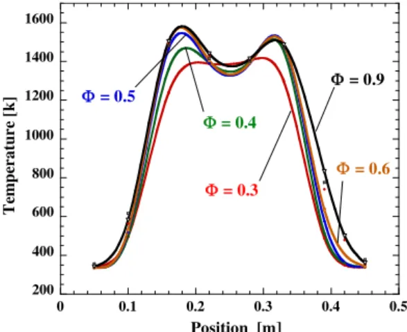
The experimental results shown inFig. 4exhibits the influence of the equivalence ratio on the temperature profiles obtained from the boiler operating at a constant gas flow velocity of 0.30 m/s. Heat extraction is performed over increasing equivalence ratios from ultra-lean mixtures (U60.2) to stoichiometry (U= 1.0). The graph shows that the temperature plateau widens and the peak temperatures slightly increase as the equivalence ratio is in-creased. Also, it illustrates that the trapezoidal temperature profile is uniform and that the thermal gradients at the burner ends are large.
It should be noted that as the value ofUincreases, the steady state temperature profile evolves from a small to an enlarged pla-teau with two temperature peaks. This enhances heat losses to the surroundings, hence lowers the temperature in the reactor midpoint.
3.2. Influence of the gas flow velocity on temperature profiles
FromFig. 5, it can be observed that the maximum values of tem-perature profiles significantly increases as the gas flow velocity in-creases, maintaining a fairly proportion between the temperature profiles. Varying the velocity of the fresh air–fuel mixture from 0.2 m/s to 0.6 m/s raises the maximum combustion temperature from 1300 K to 1600 K. When the gas flow velocity is increased, the temperature in the regions close to the flanges gets slightly augmented because the conduction and convection processes are altered.
Although the gas flow velocity only slightly affects the unifor-mity of the temperature distribution inside the porous medium, in the boiling process its effects are strong. A small increase of the temperature plateau means a strong increase in the energy storage, and hence higher heat transfer. Despite this, the gas flow velocity increases the exhaust temperature and that partially ex-plains the slightly higher temperature points at the burner ends.
As mentioned before, at higher gas flow velocity and higher equivalence ratio there is a tendency of instability phenomena, so that the boiler becomes more difficult to be operated. It seems to be in agreement with the prediction of a previous numerical
study[6], concerning the effects of the extraction energy from this kind of superadiabatic burner. Contarin et al. has expected that the gas flow velocity for a good operation condition is to be ranged from 0.15 to 0.45 m/s, what corresponds to the low-velocity re-gime of the combustion wave propagation in a porous medium [1,4,6].Fig. 6shows the instability occurrence inside the burner, featured by relatively high temperatures at the heat exchanger re-gions (burner ends). Also, the temperature distribution tends to present a non-regular profile in this condition.
3.3. Exhaust temperatures
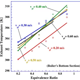
Figs. 7 and 8show both the effects of the gas flow velocity and equivalence ratio on the exhaust temperature. Observing both graphs it is possible to realize that all exhaust temperature profiles can be represented by straight lines with slight difference between the inclination angles for both boiler sections. Besides, some fea-tures should be analyzed:
First, the exhaust temperatures are very low when compared to the conventional boiler’s exhaust at any operation condition, inde-pendently on the equivalence ratio or the gas flow velocity em-ployed in the experiment. This is probably related to the fact of the combustion heat that would be lost by convection through the exhaust is absorbed by the porous medium and transferred to the heat exchangers. These reduced exhaust temperatures sig-nalizes a high thermal efficiency at the boiler.
Secondly, the inclination of the exhaust temperature variation line slightly changes as the gas flow velocity is increased, exhibit-ing good process stability. However, it should be commented that to operate the boiler at extreme conditions, or at ultra-low equiv-alence ratios and low gas flow velocities or close to stoichiometry with high gas flow velocity, there is a tendency of occurring insta-bilities in the combustion or in the boiling process.
Thirdly, the exhaust temperature values at the boiler’s bottom section with gas flow velocity of 0.3 m/s is higher than at 0.4, 0.5 and 0.6-m/s, under an ultra-low equivalence ratio range. That can be explained by the water condensation of the combustion products that takes place at the bottom section of the boiler. Employing higher gas flow velocities in the operation the conden-sate is easily carried through the exhaust.
3.4. NOxand CO emissions
The RFPBB should be considered a unique thermal device be-cause of its design features and on special its capacity to produce
200 400 600 800 1000 1200 1400 1600
0 0.1 0.2 0.3 0.4 0.5
T
em
p
er
a
tur
e [
k
]
Position [m]
Φ= 0.9
Φ = 0.3 Φ = 0.4
Φ= 0.5
Φ= 0.6
Fig. 4.Influence of the equivalence ratio on the temperature profile (vgf= 0.30 m/s).
200 400 600 800 1000 1200 1400 1600
0 0.1 0.2 0.3 0.4 0.5
T
em
p
er
a
tur
e
[K
]
v gf= 0.6 m/s
v gf= 0.5 m/s
v gf= 0.4 m/s
v gf= 0.3 m/s
v gf= 0.2 m/s
Position [m]
Fig. 5.Influence of the gas flow velocity on the temperature profile.
200 400 600 800 1000 1200 1400 1600
0 0.1 0.2 0.3 0.4 0.5
T
emp
er
atur
e [K]
Position [m]
v
gf= 0.30 m/s v
gf= 0.60 m/s
such low CO and NOxemissions, when compared to the conven-tional ones. The emission profiles of both gases are analyzed, rang-ing the equivalence ratio and the gas flow velocity between 0.2 and 1.0 and between 0.2 and 0.6 m/s, respectively.
The effects of equivalence ratio on the CO production for differ-ent gas flow velocities, shown atFig. 9, should be analyzed in de-tail. Based on this figure, it is possible to observe that increasing the gas flow velocity results in higher CO production. That can be partially explained by the higher fuel amount employed in the combustion process and by the lower available time for the oxida-tion of the CO as gas flow velocity is increased. Besides, the opera-tion temperature in reciprocal filtraopera-tion combusopera-tion, ranging between 1300 and 1600 K (burning methane), is a favorable envi-ronment to generate several radicals, such as: H; O; OH; HO2; and
H2O2. Those radicals strongly influence the oxidation kinetics of
carbon monoxide[22].
It is also possible to observe atFig. 9that CO production starts growing sharply for equivalence ratios higher than 0.7. On the other hand, at ratios lower than 0.3 there is a slight emission in-crease. The phenomenon of the ultra-low CO production at filtra-tion combusfiltra-tion can be explained by the stored heat in the porous medium that provides two factors: activation energy
enough to burn ultra-lean or ultra-rich oxidizer-fuel mixtures and residence time enough to transform monoxide into carbon dioxide. Porous medium interstices function as micro-chambers in which alumina pellets have the responsibility of transferring the enthalpy of combustion from an interstice to another, interfer-ing with the chemical kinetic as well. Thus, the porous matrix al-lows reducing the equivalence ratio up to 0.2 (or less), when some quenching starts happening in reaction, justifying the CO emission increase. On contrary, at equivalence ratios higher than 0.7 the interstices start getting saturated of fuel, forming local rich mixtures that can justify the strong increase of CO emissions.
It should be commented that the tendency of accumulating con-densate combustion water at the bottom boiler’s section at high equivalence ratios also contributes to increase CO emissions, tend-ing to occur the mechanism known as water–gas equilibrium, sim-ulating the auto-thermal reformation. However, at equivalence ratio values lower than 0.6 CO emissions can be lesser than 0.5 ppm for the studied gas flow velocities.
It should be also noted that at the 0.5 and 0.6-m/s gas flow velocities and equivalence ratios higher than 0.8, there are reaction instabilities that interfere in the boiler operation. However, operat-ing the boiler at these gas flow velocities, part of water that would be stored in the porous medium is taken out from the burner more easily. Also, it is observed the tendency in CO emissions to get higher at ultra-low equivalence ratio (lower than 0.2) because of the quenching occurrences.
Similarly to the CO emission investigation, NOxemissions are also experimentally analyzed and some results are presented for discussion atFig. 10.
Fig. 10shows the effects of the equivalence ratio on the NOx production for different gas flow velocities, indicating that the NOxemissions increase as the equivalence ratio is increased. Based on theFig. 10, it should be noted that under ultra-low equivalence ratio (U< 0.3) NOxemissions are lower than 1.0 ppm for most of studied gas flow velocities.
However,Fig. 10 also shows that for low equivalence ratios (U< 0.5) and gas flow velocities superior to 0.3 m/s NOxemissions tend to be similar and relatively lower. This phenomenon can be explained by the fact that, in this condition, convective effects of the fresh air–fuel mixture on the alumina pellets upstream to the reaction zone tend to reduce reaction temperature. Besides, up-stream heat exchangers become relatively big in relation to the re-leased heat from the reaction zone at ultra-low equivalence ratios, and hence with low water flows the energy extraction efficiency is reduced. 300 305 310 315 320 325
0.2 0.4 0.6 0.8 1
E xhau st Te mp er at ur
e [
K
]
Equivalence Ratio
v
gf= 0.50 m/s
v
gf= 0.20 m/s
v
gf= 0.40 m/s
v
gf= 0.30 m/s v
gf= 0.60 m/s
(Boiler's Top Section)
Fig. 7.RFPBB’s exhaust temperature at the top boiler section for all experimented gas flow velocities.
298 300 302 304 306 308 310
0.2 0.4 0.6 0.8 1
E x h a ust T em p er a tur
e [
K
]
Equivalence Ratio
(Boiler's Bottom Section) v
gf= 0.60 m/s
v
gf= 0.50 m/s
v
gf= 0.40 m/s
v
gf= 0.30 m/s
v
gf= 0.20 m/s
Fig. 8.RFPBB’s exhaust temperature for the boiler bottom section for all experi-mented gas flow velocities.
0.1 1 10 100
0.2 0.4 0.6 0.8 1
CO Em
is sion s [ p pm ] Equivalence Ratio v
gf= 0.50 m/s v
gf= 0.30 m/s v
gf= 0.40 m/s
v
gf= 0.60 m/s
v
gf= 0.20 m/s
(Methane)
In general way, for better understanding of the NOxemission process, some arguments should be invoked: (i) the fact that the combustion temperature is low (1300–1600 K) reduces the possi-bility of NO production through the Zeldovich mechanism[23]; (ii) it is also expected the peaks of the intermediate species to be low on a wide reaction zone, however there are possibilities of occurring the N2O-intermediate mechanism at ultra-lean mixtures
and of being produced some intermediate species, such as the rad-icals O, OH, and CH, which are important on the Fenimore mecha-nism [19]; and (iii) the reciprocating combustion temperature distribution affects on the NO production, so that, as the combus-tion temperature increases during a half cycle, the NO emission trends increases too.
3.5. Extraction efficiency
The RFPBB’S design has been developed focusing two goals: ul-tra-low emissions and high efficiency. Based on that, two heat exchangers pairs were employed in porous burner’s ends to im-prove the energy extraction from the zone reaction and the opera-tional stability as well. The heat exchangers confine the combustion wave propagation between the limits stated by them set at the burner’s ends, which act as a kind of thermal barrier for the front. Therefore, an amount of water in the heat exchangers (at both the burner’s sections) is proportionally adjusted to the re-leased heat and to the gas flow direction.
To calculate the energy extraction efficiency of this thermal sys-tem involves performing the process energy balance, taking in ac-count: the power extracted from reaction through the heat exchangers (QExtract); the chemical power of the fuel that gets into the reactor (QChem); the power dissipated through the burner’s walls (QWalls); and the power lost through the exhaust with the burned gases (QConvect). So, this energy balance should be expressed by the following equation
QExtract¼Q_ChemQ_WallsQ_Convect ð1Þ
The chemical power is obtained from the product of the mass fuel flow rate using Low Heating Value (LHV), which is expressed by the following equation:
_
QChem¼ ðm_ LHVÞCH4 ð2Þ
The released heat portion from the reaction taken out through the burned gases (Qconvect) is estimated through the enthalpy (hi) and the mass flux (mi) of the combustion products, taking into
account the measurements from gas analyzers, exhaust tempera-tures, and oxidizer–fuel mixture consumptions, which can be ex-pressed by:
QConvect¼
X
ðm_ihiÞproducts ð3Þ
The heat portion related to the losses through the reactor walls
(QWalls) is taken in account, based on the temperature distribution
profile inside the reactor, which presents high temperature gradi-ents at the reactor ends due to the heat exchangers presence, and these heat losses should be integrated. Therefore, the heat flux through the reactor walls is considered as a function of the reactor length, which is expressed by the following expression:
QWalls¼
Z 150
0
_
qtopsectiondxþ
Z 350
150
_
qreactionzonedx
þ
Z 500
350
_
qbottomsectiondx ð4Þ
Fig. 11 shows measurements of the extraction energy from
reaction through the water flow, expressed in kilowatt per square meter, considered here as specific extraction power of the boiler. It is possible to realize that the energy extraction in function of the equivalence ratio and gas flow velocity presents a profile quite linear.
Thus, the heat extraction efficiency (
g
Extract) was determined as a ratio between the averaged power transferred to the water stream and the total chemical power provided by the flowing fuel/air mixture, which is expressed by following equation:g
Extract¼QExtract
_
QChem
ð5Þ
The experimentally measured energy extraction efficiencies are in the range from 73% to 94%, depending on the equivalence ratio and gas flow velocity employed, as shown atFig. 12. Based on this figure, efficiencies increase with the equivalence ratio and the gas flow velocity, however it suggests that it would be advantageous to increase the gas flow velocity as the equivalence ratio was de-creased in order to obtain uniform energy extraction efficiency close to 90%. At the 0.6-m/s gas flow velocity instability phenom-ena occured, so that this figure could not be completed. A high turndown ratio is an intrinsic feature of the boiler operating with reciprocal filtration combustion because of the internal self-adjust-ment of the reaction zone and temperature profile to the combus-tion load. As a result, high operating efficiencies are sustained over a wide range of equivalence ratios and gas flow velocities.
0 2 4 6 8 10 12 14
0.2 0.4 0.6 0.8 1
NO
x
Em
is
si
o
n
s [p
pm]
Equivalence Ratio v
gf= 0.40 m/s
v
gf= 0.50 m/s
v
gf= 0.60 m/s
v
gf= 0.20 m/s
v
gf= 0.30 m/s
Fig. 10.RFPBB’s NOxemissions for all experimented gas flow velocities.
0 200 400 600 800 1000 1200 1400
0 0.2 0.4 0.6 0.8 1
vgf= 0.50 m/s
v
gf= 0.40 m/s
v
gf= 0.30 m/s
v
gf= 0.20 m/s v
gf= 0.60 m/s
Qex
tr
[k
W/
m
2 ]
Equivalence Ratio
It should be commented that the efficiency results obtained with that laboratory-scale prototype could be higher considering that the heat losses effects are especially strong at the small exper-imental setup due to the high area–volume ratio.
3.6. Steam production
Fig. 13shows that at a wide operation condition, combining the gas flow velocity and equivalence ratio ranges, the boiler presents a fairly linear steam production for most of the cases. This graph shows that there is a steam production increase when the gas flow velocity is raised. In consistency with other results presented so far, instabilities become realizable when the equivalence ratio val-ues overcome 0.8 at gas flow velocity superior to 0.5 m/s.
In this condition, there is the tendency of reducing steam gen-eration. The heat exchanger’s temperature at the boiler section that is receiving a fresh air–fuel mixture (upstream) reduces rapidly. To the contrary, the steam flow temperature at another boiler section (downstream), in which there is a strong heat transfer from the burned gases, increases quickly. These sudden temperature in-creases create instabilities at the boiling process with possibility of influencing on the combustion stability.
Fig. 14shows saturated steam temperatures leaving the boiler at the bottom and top sections. For instance, applying a 500-kPa operation pressure in the water pumping, 425-K steam tempera-tures are obtained at both sections. This graph only shows an instantaneous sample from regular operation conditions, proving that RFPBB maintains the same temperature fluctuation level at the steam outlet, for any equivalence ratios and gas flow velocities applied to the experiments. Based on this figure, one sees how sta-ble the boiler is after reaching the steady state, in which the steam temperature variation at the outlet is of approximately ±3 K. This is one of the most important features of this kind of steam boiler.
4. Conclusions
This high efficiency low-emission steam boiler has been suc-cessfully developed employing reciprocal filtration combustion at its burner and the conclusions are summarized below:
(1) The temperature profile has a typical trapezoidal shape with a minimum at the reactor midpoint. The heat exchangers did not allow an expansion of the temperature distribution to the burner ends.
(2) The presence of heat exchangers confines the reaction zones in the central insulated section, allowing stable combustion for the wide equivalence ratio range.
(3) The heat exchangers work in high temperature condition and the energy extraction from the stainless steel heat exchanger is not sufficient to quench the burner.
(4) A stable combustion at the boiler was found running a wide operation condition range, 0.20 <U< 1 and 0.20 <
v
gf< 0.6 m/s.(5) Reciprocal filtration combustion provides not only efficient energy extraction and low emissions but also a high degree of stability for the burner.
(6) The equivalence ratio and the gas flow velocity exhibit a strong influence on the temperature profiles, efficiency and emissions.
(7) NOxand CO molar fractions increase from 0.2 and 0.5 ppm, respectively, to 10 ppm for a wide ultra-low equivalence ratio range (0.2 <U< 0.8).
(8) The experimental results have pointed out that RFPBB has reached efficiencies of about 90% at any experimented gas flow velocity under a wide equivalence ratio range (0.20 <
U< 0.9).
60 70 80 90 100
0.2 0.4 0.6 0.8 1
Equivalence Ratio
η
extract(%)
v
gf= 0.50 m/s vgf= 0.60 m/s
v
gf= 0.40 m/s v
gf= 0.30 m/s
v
gf= 0.20 m/s
Fig. 12.RFPBB’s energy extraction efficiency for all experimented gas flow velocities.
0 1 2 3 4 5 6 7
0.2 0.4 0.6 0.8 1
S
team Pr
odu
ction
[g/s]
Equivalence Ratio v
gf= 0.50 m/s v
gf= 0.60 m/s
v
gf= 0.30 m/s v
gf= 0.40 m/s
v
gf= 0.20 m/s
Fig. 13.RFPBB’s steam production for all experimented gas flow velocities.
400 410 420 430 440 450
0 50 100 150 200 250
S
team
Fl
ow Te
mp
er
atur
e
[
K
]
Bottom Section
Top Section
Time [s]
(Pressure = 500 kPa)
Acknowledgments
This work was supported by two Brazilian Government’s Scien-tific and Technological Development Institutions: FUNCAP (Cea-rense Foundation of Support to the Scientific and Technological Development) and CNPq (National Council of Technological and Scientific Development).
References
[1] V.S. Babkin, Filtration combustion of gases, present state of affairs and prospects, Pure and Applied Chemistry 65 (1993) 335–344.
[2] W.M. Barcellos, F. Contarin, A.V. Saveliev, L.A. Kennedy, Energy extraction from a porous media reciprocal flow burner with embedded heat exchangers, Journal of Heat Transfer 127 (2005) 123–130.
[3] W.M. Barcellos, A.V. Saveliev, L.A. Kennedy, Low emission saturated steam boiler with reciprocal flow inert porous media combustor operating on ultra-lean natural gas/air mixtures, in: Proceedings of the Fifth International Conference on Technologies and Combustion for a Clean Environment, Clean Air Conference, Lisbon, Portugal, 2003.
[4] J.P. Bingue, A.V. Saveliev, A.A. Fridman, L.A. Kennedy, NOxand CO emissions of
lean and ultra-lean filtration combustion of methane/air mixtures in inert porous media, in: Proceedings of the Fifth International Conference on Technologies and Combustion for a Clean Environment, Lisbon, Portugal, 1998, pp. 1361–1367 .
[5] F. Contarin, W.M. Barcellos, A.V. Saveliev, L.A. Kennedy, A porous media reciprocal flow burner with embedded heat exchangers, in: Proceedings of the ASME Summer Heat Transfer Conference – Paper No. HT2003-47098, 2003. [6] F. Contarin, A.V. Saveliev, A.A. Fridman, L.A. Kennedy, A reciprocal flow
filtration combustor with embedded heat exchangers: numerical study, International Journal of Heat and Mass Transfer 36 (2003) 949–961. [7] M.K. Drayton, A.V. Saveliev, L.A. Kennedy, A.A. Fridman, Y.E. Li, Syngas
production using superadiabatic combustion of ultra-rich methane air mixtures, Proceedings of the Combustion Institute 27 (1998) 1361–1368. [8] K. Hannamura, R. Echigo, S. Zhdanok, Superadiabatic combustion in porous
media, International Journal of Heat and Mass Transfer 36 (1993) 3201–3209. [9] J.G. Hoffmann, R. Echigo, H. Yoshida, S. Tada, Experimental study on combustion in porous media with a reciprocating flow system, Combustion and Flame 111 (1997) 32–46.
[10] F. Katsuki, T. Tomida, H. Nakatani, M. Katoh, A. Takata, Development of a thermoelectric power generation system using reciprocating flow combustion in a porous FeSi2element, Review of Scientific Instruments 72 (10) (2001) 3996–3999.
[11] L.A. Kennedy, A.A. Fridman, A.V. Saveliev, Superadiabatic combustion in porous media: wave propagation, instabilities, new type of chemical reactor, Fluid Mechanics Research 22 (1995) 1–26.
[12] M. Kureta, T. Kobayashi, K. Nishihara, Pressure drop and heat transfer for flow-boiling of water in small-diameter tubes, JSME International Journal Series B 41 (1998) 871–879.
[13] D. Littlejohn, A.J. Majeski, S. Tonse, C. Castaldini, Laboratory investigation of an ultra-low NOx premixed combustion concept for industrial boilers,
Proceedings of Combustion Institute 29 (2002) 1115–1121.
[14] A.A. Mohamad, R. Viskanta, S. Ramadhyani, Numerical predictions of combustion and heat transfer in a packed bed with embedded coolant tubes, Combustion Science and Technology 96 (1994) 387–407.
[15] M.A. Mujeebu, M.Z. Abdullah, M.Z. Abu Bakar, A.A. Mohamad, M.K. Abdullah, Applications of porous media combustion technology – a review, Applied Energy 86 (2009) 1365–1375.
[16] M.A. Mujeebu, M.Z. Abdullah, M.Z. Abu Bakar, A.A. Mohamad, R.M.N. Muhad, M.K. Abdullah, Combustion in porous media and its applications – a comprehensive survey, Journal of Environmental Management 90 (2009) 2287–2312.
[17] C.W. Park, M. Kaviany, Combustion-thermoelectric tube, Journal of Heat Transfer 122 (4) (2000) 721–729.
[18] B. Sumith, F. Kaminaga, K. Matsumura, Saturated flow boiling of water in a vertical small diameter tube, Experimental Thermal and Fluid Science 27 (2003) 789–801.
[19] S.R. Turns, An Introduction to Combustion – Concepts and Applications, McGraw-Hill, Inc., 2000.
[20] S. Wood, A.T. Harris, Porous burners for lean-burn applications, Progress in Energy and Combustion Science 34 (2008) 667–684.
[21] T.Y. Xiong, M.J. Khinkis, F.F. Fish, Experimental study of a high-efficiency, low emission porous matrix combustor–heater, Fuel 74 (1995) 1641–1647. [22] R.A. Yetter, F.L. Dryer, A comprehensive reaction mechanism for carbon
monoxide/hydrogen/oxygen kinetics, Combustion Science and Technology 79 (1991) 97–128.
[23] R.A. Yetter, F.L. Dryer, Flow reactor studies of carbon monoxide/hydrogen/ oxygen kinetics, Combustion Science and Technology 79 (1991) 129–140. [24] S.A. Zhdanok, L.A. Kennedy, G. Koester, Superadiabatic combustion of methane