SENSORS INTEGRATION FOR SMARTPHONE NAVIGATION: PERFORMANCES
AND FUTURE CHALLENGES
I. Aicardi a, P. Dabove a, A. Lingua a, M. Piras a
a
Politecnico di Torino, DIATI – Department of Environmental, Land and Infrastructure Engineering, Torino, Italy – (irene.aicardi – paolo.dabove – andrea.lingua – marco.piras)@polito.it
Commission III, Symposium 2014
KEY WORDS: Calibration, Inertial sensor, Localization, Navigation, SIFT, Smartphone
ABSTRACT:
Nowadays the modern smartphones include several sensors which are usually adopted in geomatic application, as digital camera, GNSS (Global Navigation Satellite System) receivers, inertial platform, RFID and Wi-Fi systems.
In this paper the authors would like to testing the performances of internal sensors (Inertial Measurement Unit, IMU) of three modern smartphones (Samsung GalaxyS4, Samsung GalaxyS5 and iPhone4) compared to external mass-market IMU platform in order to verify their accuracy levels, in terms of positioning. Moreover, the Image Based Navigation (IBN) approach is also investigated: this approach can be very useful in hard-urban environment or for indoor positioning, as alternative to GNSS positioning.
IBN allows to obtain a sub-metrical accuracy, but a special database of georeferenced images (Image DataBase, IDB) is needed, moreover it is necessary to use dedicated algorithm to resizing the images which are collected by smartphone, in order to share it with the server where is stored the IDB. Moreover, it is necessary to characterize smartphone camera lens in terms of focal length and lens distortions.
The authors have developed an innovative method with respect to those available today, which has been tested in a covered area, adopting a special support where all sensors under testing have been installed. Geomatic instrument have been used to define the reference trajectory, with purpose to compare this one, with the path obtained with IBN solution. First results leads to have an horizontal and vertical accuracies better than 60 cm, respect to the reference trajectories. IBN method, sensors, test and result will be described in the paper.
1. INTRODUCTION
During the last years, the possibility to know our position has becoming more and more important. The users want to use their devices to get this information (for example for location based services) and to share it to other people.
Nowadays, the most common device are based on smartphones technology, where several sensors are installed, as GNSS (Global Navigation Satellite System) receiver, video-cameras, pressure sensor, inertial Measurement Unit (IMU) with accelerometers, gyroscopes and magnetometers. All of them contribute to define a 3D position, but they could be used for Geomatics purpose also.
As known, in greater part of the cases GNSS receiver is adopted for outdoor positioning, where it allows to reach a good level of precision, but somewhere the signal is too noisy or not available (i.e. indoor or urban canyons) and GNSS positioning is not allowed. The future trend of positioning is to have a seamless solution, that means to have a continuous and stable localization everywhere, from outdoor to indoor scenario.
In the last years, many research groups are working to study different solutions to bridge this gap, as alternative to GNSS positioning, using different kind of sensors.
Summarizing the main available technologies, it is possible to divide them considering the different fields:
Wi-Fi: this technology is especially dedicated for indoor environments in a transmission range between 30-200 m. In particular, the positioning is based on the time-of-flight range measurements observed from several base stations applying a triangulation. This procedure brings to have good performance, but it
suffers from outliers, signal coverage and depends to Access Points (AP) and geometric distribution (DoP) (Schatzberg et al., 2014; Hatami et al., 2005; Werner et al., 2014);
pedestrian tracking system: this procedure is based on
the use of a pedometer, that is now also available in the modern smartphone (Yunye et al., 2011; Woodman and Harle, 2008; Shin et al., 2014). The possibility to adopting external sensors as low-cost IMU-MEMS (Micro Electro-Mechanical Systems), which was directly installed on the foot of the user has been investigated (Yuan et al., 2014);
Bluetooth: the technology is based on the use of Bluetooth Low Energy by adding direction finding capability (Kallioka, 2011). There is also another approach based on a range-free localization system using commercial smartphones with Bluetooth capabilities. In the range-free localization system, each smartphone periodically scans nearby Bluetooth enabled devices and sends the results to the localization server. This server collects the scanning results into a short period and find their locations using range-free algorithms (Lee et al. 2014).
Inertial sensor navigation (Woodman 2007): another
alternative approach is to use the accelerometers (Kunze et al. 2009), the gyroscope and magnetometers in the pedestrian navigation in order to correct the drifts (Afzal et al. 2011) and also in the use of barometer sensor to identify the movements (Frank et al. 2014), with purpose to realize a navigation.
Positioning and navigation are usually estimated adopting an The International Archives of the Photogrammetry, Remote Sensing and Spatial Information Sciences, Volume XL-3, 2014
integration between the techniques described above, in order to improve the accuracy and the precision. Nowadays, the range of precision for positioning with these techniques is between 50 m to 60 cm. The accuracy and precision level mainly depends to the data processing, especially in the most of cases the positioning are estimated using the Kalman filter. It is very useful when inertial sensor are adopted, with purpose to predict the bearing of the object.
The proposal of the authors is based on the integration between images and inertial sensors which are included in the modern smartphones, developing an innovative integration approach. A positioning procedure based only on the use of the images have been tested, obtaining an accuracy equal around to 30 cm. After that, the inertial sensors have been considered in order to estimate an integrated solution of navigation.
2. THE IMAGE-BASED NAVIGATION APPROACH
The Image-Based Navigation (IBN) procedure is an approach devotes to define position and attitude of the user, in real time navigation using images and photogrammetric algorithms, and eventually inertial sensors (De Agostino et al., 2010).
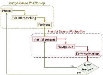
The IBN can be realized in different ways, in particular in this research the authors have following these steps (Figure 1):
it is initialize through a first photo that represent the starting point for the localization;
then the navigation go on using the inertial sensors that indicate to the user the direction and attitude to follow;
after a specific time a new image is needed in order to correct the inertial drift.
Figure 1 - The Image-Based Navigation procedure
To explain, the IBN has been divided in two phases:
image-based localization (IBL); inertial sensors navigation (ISN).
The IBL is based on the matching between each photo and a reference image extracted from a database of 3D images. As it is better described in chapter 4, the IDB is defined by solid images (Bornaz et al., 2003, Forno et al, 2013) that defines a 3D information of the position. The IBL procedure adopts well-known algorithms for image matching, such as SIFT and RANSAC. In particular, the method is realized as described in the following:
A. the matching between the two images is realized in this way:
common features are extracted between the real time image and the reference one using the SIFT algorithm (Li et al., 2011);
key points are matched;
the estimation of the fundamental matrix using RANSAC, in order to detect other outliers which were not previously detected.
Image Based Navigation approach can help to estimate and correct the inertial sensors drift, in order to improve the quality of positioning up to 0.4 m. (Lingua et al. 2014) (Piras et al., 2014).
After that, the reference image has been directly extracted from the 3D IDB. The second step is to using this image to estimate the 3D position:
B. parameters estimation:
the common features are translate in 3D information using the related solid image
11 DLT parameters are estimated using the common points detected trough the features and are decoded to obtain the exterior orientation parameters in the first approximation;
using the collinearity equations, the external orientation parameters are defined.
the navigation solution (attitude, position) has been estimated.
Concerning the ISN procedure, it starts with the analysis of the raw data of inertial sensors (acceleration, angular velocity and magnitude of magnetic field), that can be directly registered from the smartphone using “ad hoc” Android APPs. First of all, it is necessary to filter these data, as it is better described in the next part, in order to analyse the noise. Then the navigation solution is extracted using a dedicated software developed at the Politecnico di Torino and written in MATLAB® languages This software was created to integrate GNSS and IMU solutions, but now it is adapted in order to introduce the image solution.
3. DESCRIPTION OF THE USED SENSORS
The IBN procedure can be adopted also for mass-market devices, in particular the most popular sensors today available are smartphone that now include many sensors useful for Geomatics applications.
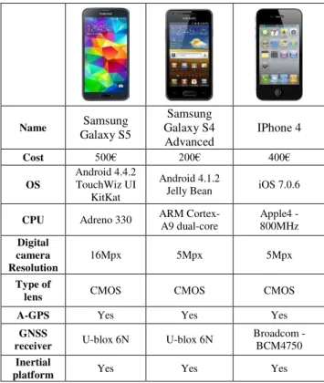
In this paper, the performance of the most famous devices available off the shelf have been tested: Samsung Galaxy S4 Advanced, Samsung Galaxy S5 and IPhone 4. They have embedded different internal sensors, such as digital camera and GNSS receivers, even inertial platform based on gyroscopes, accelerometers and magnetometers and RFID system for smartphone devices. The technical characteristics of each one are described in (Table 1).
These devices include sensors whose characteristics must be known in order to realize a good positioning. In particular, it is fundamental to characterize the noise level of the inertial sensors and calibrate the camera, with purpose to remove the lens distortions, which is fundamental for realizing a positioning with a photogrammetric approach.
3.1 Sensors calibration
For the IBN we can take into account the errors due to: camera lens distortions;
inertial sensor distortions.
The digital camera embedded in the smartphone are not-metric sensors, so they require a calibration through an analytical procedure in order to study their characteristics and to know the mechanical-digital distortion parameters.
Name Samsung
Galaxy S5
Samsung Galaxy S4 Advanced
IPhone 4
Cost 500€ 200€ 400€
OS
Android 4.4.2 TouchWiz UI
KitKat
Android 4.1.2
Jelly Bean iOS 7.0.6
CPU Adreno 330 ARM Cortex-A9 dual-core
Apple4 - 800MHz Digital
camera Resolution
16Mpx 5Mpx 5Mpx
Type of
lens CMOS CMOS CMOS
A-GPS Yes Yes Yes
GNSS
receiver U-blox 6N U-blox 6N
Broadcom - BCM4750 Inertial
platform Yes Yes Yes
Table 1 - Devices and their principal characteristics
As well known, the optical system is composed by a set of lenses with different curve shape. Lenses are pieces of glass conveniently burnished having a spherical surface; the centre of curvature of each portion of sphere is located on a straight line also called lens optical axis. Thanks to its spherical shape, it is possible to deviate ray light flowing through lenses.
A real photogrammetric lens has significant differences with respect to the ideal one because:
the lens assembly misalignment;
the photogrammetric reference axis will not be the optical axis, but a principal calibrated that, in the object space, is perpendicular to the image plane;
the refractive and incidence angles do not match; the main distance is slightly different from the main optical distance;
the image plane is not perfectly perpendicular to the optical axis.
At the end, the principal distance variation (Δc) is calculated, trying to lead the mean value to zero.
These distortion curves could be represented using an odd -degree polynomial function in ρ (distance from principal point position inside image plane) :
(1)
(2)
(3)
In some sort of cameras, especially amateur one, it should be considered even tangential distortion:
[ ] (4)
[ ] (5)
In the other hand, sensor is made of silicon wafer that is substantially static in terms of geometry. However there exist a distortion effect related to the geometry of the sensor: in theory a pixel should be a perfect square and the rows matrix should be perpendicular to the columns; in reality this does not happen. Such distortion is time constant, depends only on sensor construction, and is conveyed by a particular affine transformation:
(6) So, using mass market devices is crucial to calibrate the lens in order to know and model these parameters (Aicardi et al. 2014). In particular, in this case, the radial distortions are only considered because it has the most impact in the image distortion. Tangential distortions have not been considered, because the effects are not appreciable.
The analytical calibration mode of the cameras are usually divided into on-the-job calibration and self-calibration, which are based on the solution of the calculation of a
bundle-adjustment performed considering as unknowns the six external
orientation parameters of the images and the six parameters of the camera calibration (ξ0, η0, c, K1, K2, K3) (Kraus, 1997).
Figure 2 - Calibration field
In this application, the self-calibration procedure has been used. This is based on the determination of the calibration parameters carried out independently by the procedures of the photogrammetric survey. This method is usually performed by preparing a calibration grid, specifically made, in which the coordinates of the target are known with extreme precision. The calibration has been realized using a dedicated calibration field, which is externally materialized in the Geomatics Laboratory at the Politecnico di Torino (Figure 2).
The software Leica Photogrammetric Suite (LPS) by ERDAS has been used for the self-calibration of the device. For all devices, the distortions have been estimated and they are reported in Figure 3, Figure 4 and Figure 5.
As it is shown in Table 2, the Samsung S4 is the smartphone with minor radial distortion that, correcting it by a linear trend, can be neglected. The others two devices have a similar distortion pattern which is about twice then the first one. Another aspect that has to be considered is the stability of the internal inertial sensors, whose performances are usually not declared. So, we performed a 6 hours static test in order to acquire the raw data (angular velocity and accelerations) of each Smartphone and we analyse the stability.
Figure 3 - Radial lens distortion resulting from Samsung S4 calibration
Figure 4 - Radial lens distortion resulting from Samsung S5 calibration
Figure 5 - Radial lens distortion resulting from IPhone4 calibration
The analysed parameters are related to the acceleration and gyroscope, and also to the attitude, which is real time calculated from the inertial platform and could be used as the “a priori” attitude for the IBN.Figure 6, Figure 7 and Figure 8 show the result of the Samsung S4 inertial platform analysis. Same analysis has been conducted for the Samsung S5, obtaining the following results (Figure 9, Figure 10, Figure 11).
[µm] Samsung S4 Samsung S5 IPhone4
max 10,24 35,74 33,57
resmax 3,58 7,20 6,59
Table 2 - Devices radial distortion
Figure 6 - Acceleration residuals for Samsung S4
Figure 7 - Gyroscope residuals for Samsung S4
Figure 8 - Roll, Pitch and Yaw stability for Samsung S4
As it is possible to see in the next graphs, it seems that the accelerometers of Samsung Galaxy S5 are better than the Samsung S4 ones, while the gyros of S5 are worse than S4. Also the attitude is quite different: while in the Samsung S4 the Roll component is quite noisier, in the Galaxy S5 both roll and yaw components are very stable.
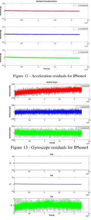
The stability and the performances of the IPhone4 are described in Figure 12, Figure 13 and Figure 14.
y = 3,4824x R2 = 0,8118
-6,00 -4,00 -2,00 0,00 2,00 4,00 6,00 8,00 10,00 12,00
0 0,5 1 1,5 2 2,5 3
r [mm]
D
r
[m
ic
ron]
Dr Dr residual Trend
y = 8,179x R2 = 0,8708
-10,00 -5,00 0,00 5,00 10,00 15,00 20,00 25,00 30,00 35,00 40,00
0 0,5 1 1,5 2 2,5 3 3,5 4 4,5
r [mm]
D
r
[m
ic
ron]
Dr Dr residual Lineare (Dr)
Figure 9- Acceleration residuals for Samsung Galaxy S5
Figure 10 - Gyroscope residuals for Samsung Galaxy S5
Figure 11 - Roll, Pitch and Yaw stability for Samsung S5
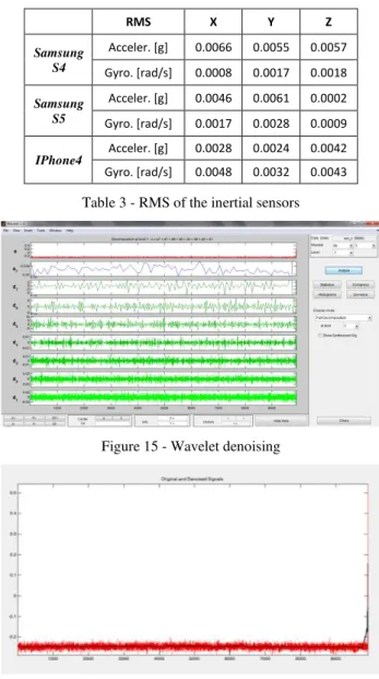
Starting from Table 3 it is possible to note that in general the accelerometers of Samsung S5 are slightly better than the S4 ones while it is the opposite for the gyro components.
In general it is possible to affirm that the iPhone4 accelerometers are the best (if these three smartphones are compared) while the gyros are the worst. It must to be underlined that in this paper we don’t want to determine which smartphone is the “best” but which of them is more useful for Image Based Navigation purposes.
Figure 12 - Acceleration residuals for IPhone4
Figure 13 - Gyroscope residuals for IPhone4
Figure 14 - Roll, Pitch and Yaw stability for IPhone4
For the inertial sensors, it is possible to try to correct the noise of the data making a filtering. To make this it is possible to use the wavelet, which are signal representations by the use of a waveform oscillating. There are different kinds of these representations, but, for this case, the Daubechies wavelets were chosen to correct the data and, in particular, we used a Daubechies4 at a Level7.
In Figure 15, it is possible to see the wavelet de-noising approach thanks to the Matlab toolbox while in Figure 16 it is reported an example of the signal after the wavelet filtering (in red it is possible to see the original signal while in black the de-noised one).
RMS X Y Z
Samsung S4
Acceler. [g] 0.0066 0.0055 0.0057
Gyro. [rad/s] 0.0008 0.0017 0.0018
Samsung S5
Acceler. [g] 0.0046 0.0061 0.0002
Gyro. [rad/s] 0.0017 0.0028 0.0009
IPhone4 Acceler. [g] 0.0028 0.0024 0.0042
Gyro. [rad/s] 0.0048 0.0032 0.0043
Table 3 - RMS of the inertial sensors
Figure 15 - Wavelet denoising
Figure 16 - Original (red) and de-noised (black) signals
4. 3D SOLID IMAGE DATABASE GENERATION
In IBN, the position of the image is estimated from the comparison between the image taken from the user and the reference image extract from a 3D IDB, that in this case is defined by means solid images.
A solid image is a synthetic image in which for each pixel is associated the information on the relative position of the spatial point projected on the image, expressed in 3D coordinates in a defined reference system, considering the camera parameters. These images are extracted from a 3D model that can be generated in different ways: using existing 3D City Models, making a terrestrial or an aerial survey or collecting the data trough Mobile Mapping Systems.
For this application, a terrestrial LiDAR survey has been used, that also allows the acquisition of images using an integrated camera, with purpose to obtain a coloured points cloud. Five different scans have been acquired and mounted in a single model in a common reference system. As result of the process, a geo-referenced coloured point cloud of the environment is provided, on which you can directly read 3D coordinates and colour of the points of interest: this model is used for the extraction of the images, and complementary spatial information.
Figure 17 - Examples of the image DB
Now, the solid image can be automatically generated by means of these steps (Lingua et al. 2014):
an empty solid image (RGB and range) is generated using the number of pixels in column and row of the solid image (
n
col, n
row); a subset of colored points (
Xi, Yi, Zi
) with i=1:n, (n=number of selected points) can be extracted from the original RGB point cloud according to a selection volume that can be defined by a sector of a sphere with:- center in the location of generated solid image; - axis direction coincident with the optical axis of
synthetic solid image; - radius R;
- amplitude defined by an angle ( 90°) that is half the cone angle measured from direction axis;
for each selected colored point, a distance
d
i respect the location of generated solid image is calculated:
20 2
0 2
0 Y Y Z Z
X X
di i i i
each selected RGB point is projected on the solid image defining its image coordinates by means of the internal and external orientation parameters inside the collinearity equations:
the image coordinates are converted in pixel coordinates using:
2 2
row
pox i i col
pix i i
n d r n d
c
(4) the RGB values of each point are wrote inside the cell of image RGB matrices in the position ;
the distance value
d
i is wrote inside the cell of rangeimage matrix in the position ;
at the end of the procedure, pixels still void are filled by means of an interpolation algorithm based on nearest filled pixels.
The DB can be create under different conditions, for example it is possible to set, the camera parameters, the position of the hold centre, the grip axis and the number of images for each point. At the end of the procedure, we obtain a set of images (Errore. L'origine riferimento non è stata trovata.) with the information about position and attitude. These images can be used to initialize the IBN procedure, making the first photo of the site, and to correct the navigation using a new image.
5. TEST AND CASE STUDIES
The tests have been realized in a courtyard in our campus (Figure 18). The track (red line in Figure 18) was especially The International Archives of the Photogrammetry, Remote Sensing and Spatial Information Sciences, Volume XL-3, 2014
performed in an area that present many windows and with an high repeatability of the modules.
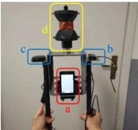
This area has been chosen to simulate urban canyon or indoor location (the GNSS data has not been acquired/used) in a convenient situation (all the area is visible from a unique total station position) with typical noise in indoor image acquisitions (walking people, variable condition of light, shadows,…). In this area, the test has been performed walking on the same path using the three different smartphones (a) mounted on a special support (Figure 19), realized by our Geomatics Laboratory, which allow to support:
an inertial platform IMU-MEMS Microstrain 3DMGX35 (b) with external antenna (c); a 360° retroflector (d).
Figure 18 - Test site and track
During the tests each smartphone sensor has recorded own inertial sensors data using a dedicated Android App, called “AndroSensor”, that gives graphical information and text (.csv) output.
The reference trajectory has been defined tracking the smartphone position in continuous with a total station, through the retroflector; in this way, the position of the support has been measured with an accuracy of few mm..
Moreover, the data from an external IMU (microstrain) has been stored using a computer, with purpose to have reference values of the attitude.
For this application different types of data were acquired from the devices, in particular:
Samsung S4: images Samsung S5: videos IPhone4: images and videos.
After the test, all of IMU data files concerning each sensor, the image/video of the tracks and the reference data for the comparison between the estimated and the real solution have been available and they have been processed.
6. FIRST RESULTS
First results highlight how the IBN improve the correctness of positioning in indoor application, in particular describe the benefit of this technique with respect the navigation IMU only or, worst, with GNSS only. A comparison of the acquired tracks with all smartphones involved in our test and the IBN solution has been realized. The result are shown in Figure 20, where the green line is the solution estimate with MEMS platform and using an integrated solution GNSS-IMU, where the GNSS data was available
Figure 19 - The system used to acquire the data
The result are shown in Figure 20, where the green line is the solution estimate with MEMS platform and using an integrated solution GNSS-IMU, where the GNSS data was available.
Figure 20 - Track results comparison
The IBN solution obtained with IPHONE sensors (red line in Figure 20) brings to reach a horizontal error loop equal to 1.4 m and a vertical error loop equal to 0.26 m, considering a session length amount to 6 minutes. The error in the angular estimation is about 1.8 gons, estimating a noise equal to 0.4 gons.
The IBN solution obtained with Samsung S4 sensors (blue line in Figure 20) brings to reach a horizontal error loop equal to 1.6 m and a vertical error loop equal to 0.33 m, considering a session length amount to 6 minutes. The error in the angular estimation is about 1.6 gons, estimating a noise equal to 0.34 gons.
Finally, considering the Samsung Galaxy S5 sensors (orange line in Figure 20) the horizontal error loop obtained is equal to 1.5 m and a vertical error loop equal to 0.38 m, considering a session length amount to 6 minutes. The error in the angular estimation is about 1.4 gons, estimating a noise equal to 0.29 gons.
7. CONCLUSIONS
The realized tests highlight that the modern smartphone can really help the user to define its position even if the actual application and technology are not developed to take the greater advantages from the internal sensors, in fact it is quite difficult to recording the raw data or to have the direct access to the internal sensor.
The performance improvement, in term of precision of position, could be obtained making a calibration of the lens and adopting specific algorithms for data analysis, in particular for outlier The International Archives of the Photogrammetry, Remote Sensing and Spatial Information Sciences, Volume XL-3, 2014
detection in the images and to filtering the IMU data. It is generally possible to affirm that the “best” solution in term of horizontal and vertical error loop is obtained with iPhone smartphone, while considering the angular estimation the Samsung Galaxy S5 provide the best results.
The accuracy of the IBN positioning depends on the definition of the three dimensional, which can be built in different way. Furthermore, working with smartphones technologies, it is important to use adequate algorithm for compressing the images, in order to send it to the server where the IDB has been stored.
These first tests have demonstrated the feasibility and the performances of the IBN with modern smartphones: in the future this approach will be investigated deeply in order to obtain better results also useful for indoor positioning.
8. ACNOWLEGMENTS
Authors would like to thank the prof. Bendea, who has realized the “butterfly” support.
A part of the research presented in the paper refers to part of the activities carried out in the Pro-VisionProject (Title: Sistema Prototipale per le Verifiche di Visibilità su Infrastrutture di Trasporto Esistenti in Ambito di Smart City), which is funded by the Regione Piemonte (F.E.S.R. 2007/2013).
Other parts of this research have been financed from TELECOM Italia by means of the project: “"Navigazione in tempo reale mediante smartphone in ambienti indoor e outdoor basandosi su tecniche di localizzazione per immagini".
9. REFERENCES
Afzal M.H., Renaudin V., Lachapelle G., 2011. Use of Earth’s Magnetic Field for Mitigating Gyroscope Errors Regardless of Magnetic Perturbation. Published in Sensors
Aicardi I., Lingua A.M., Piras M., 2014. Evaluation of mass market devices for the documentation of the cultural heritage. In 2014 ISPRS Conference, Commission V. June 23-25, Riva del Garda.
Bornaz L., Dequal S. ,2003. A new concept: the solid image. CIPA 2003 Proceedings of XIXth International Symposium: 169-174.
De Agostino M., Lingua A., Nex F., Piras M. 2010,
GIMPhI: a novel vision-based navigation approach for low cost MMS. In: Position Location and Navigation Symposium (PLANS), 2010 IEEE/ION, Indian Wells, CA, USA, 4-6 May 2010. pp. 1238-1244
Frank K., Munoz Diaz E., Robertson P., Fuentes Sanchez F.J., 2014. Bayesian Recognition of Safety Relevant Motion Activities with Inertial Sensors and Barometer. In 2014 Plans Conference proceedings. pp.174-184
Forno M.G., Lingua A., Lo Russo S., Taddia G., Piras M., 2013. GSTOP: a new tool for 3D geomorphological survey and mapping , EUROPEAN JOURNAL OF REMOTE SENSING, Davide Travaglini, pp. 16, , Vol. 46, ISSN: 2279-7254, DOI: 10.5721/EuJRS20134613
Hatami A., Pahlavan K., 2005. A Comparative Performance Evaluation of RSS-Based Positioning Algorithms Used in
WLAN Networks. IEEE Wireless Communications and Networking Conference.
Kalliola, K., 2011. High Accuracy Indoor Positioning Based on BLE. Nokia Research Center Presentation.
Kraus K., 1997. Photogrammetry II, Advanced methods and applications. Ummler/ Bonn, ISBN 3-427-78694-3.
Kunze K., Lukowicz P., Partridge K., Begole B., 2009. Which way am I facing: inferring horizontal device orientation from an accelerometer signal. In International Symposium on Wearable computers.
Lee S., Koo B., Jin M., Park C., Lee M.J., Kim S., 2014. Range-Free Indoor Positioning System Using Smartphone with Bluetooth Capability. In 2014 Plans Conference proceedings. pp.657-662
Li X., Wang J., Li R., Ding W., 2011. Image-based positioning with the use of geo-referenced SIFT features. Proceedings of the Incorporating the International Symposium on GPS/GNSS (IGNSS 2011), Sydney, Australia.
Lingua A.M., Aicardi I., Ghinamo G., Corbi C., Francini G., Lepsoy S., Lovisolo P., 2014. Technique based on 3D LIDAR scanning and MPEG7 Visual Search Solutions. In 2014 ION Conference, in press.
Piras M., Dabove P., Lingua A.M., Aicardi I., 2014. Indoor Navigation Using Smartphone Technology: A Future Challenge Or An Actual Possibility?. In 2014 Plans Conference proceedings. pp.1343-1352
Rousseeuw J.P., Leroy A.M., 1987. Robust regression and outlier detection. Wiley & Sons.
Schatzberg U., Banin L., Amizur Y., 2014. Enhanced WiFi ToF indoor positioning system with MEMs-based INS and pedometric information. Intel Corporation, Israel. In 2014 Plans Conference proceedings. pp.185-192
Shin B., Lee S., Kim C., Kim J., Lee T., Kee C., Heo S., Rhee H., 2014. Implementation and Performance Analysis of Smartphone-based 3D PDR System with Hybrid Motion and Heading Classifier. In 2014 Plans Conference proceedings. pp.201-204
Werner M., Schauer L., Scharf A., 2014. Reliable Trajectory Classification Using Wi-Fi Signal Strength in Indoor Scenarios. In 2014 Plans Conference proceedings. pp.663-670
Woodman, O., Harle R., 2008. Pedestrian Localisation for Indoor Environments. Proc. UbiComp, Seoul, Korea.
Woodman O.J., 2007. An introduction to inertial navigation. Technical report
Yuan X., Liu C., Zhang S., Yu S., 2014. Indoor Pedestrian Navigation Using Miniaturized Low-Cost MEMS Inertial Measurement Units. In 2014 Plans Conference proceedings. pp.487-492
Yunye J., Hong-Song T., Wee-Seng S., Wai-Choong W., 2011. A Robust Dead-Reckoning Pedestrian Tracking System with Low Cost Sensors. In 2011 IEEE International Conference on Pervasive Computing and Communications