PHOTOGRAMMETRIC PROCESSING USING ZY-3 SATELLITE IMAGERY
W. Kornus, A. Magariños, M. Pla, E. Soler, F. Perez,
a Institut Cartogràfic I Geològic de Catalunya (ICGC), Parc de Montjuïc, E-08038 Barcelona
KEY WORDS: ZY-3, Satellite Photogrammetry, DEM/DTM, Orthoimage, Stereo-Plotting, Accuracy
ABSTRACT:
This paper evaluates the stereoscopic capacities of the Chinese sensor ZiYuan-3 (ZY-3) for the generation of photogrammetric products. The satellite was launched on January 9, 2012 and carries three high-resolution panchromatic cameras viewing in forward (22º), nadir (0º) and backward direction (-22º) and an infrared multi-spectral scanner (IRMSS), which is slightly looking forward (6º). The ground sampling distance (GSD) is 2.1m for the nadir image, 3.5m for the two oblique stereo images and 5.8m for the multispectral image. The evaluated ZY-3 imagery consists of a full set of threefold-stereo and a multi-spectral image covering an area of ca. 50km x 50km north-west of Barcelona, Spain. The complete photogrammetric processing chain was executed including image orientation, the generation of a digital surface model (DSM), radiometric image correction, pansharpening, orthoimage generation and digital stereo plotting.
All 4 images are oriented by estimating affine transformation parameters between observed and nominal RPC (rational polynomial coefficients) image positions of 17 ground control points (GCP) and a subsequent calculation of refined RPC. From 10 independent check points RMS errors of 2.2m, 2.0m and 2.7m in X, Y and H are obtained. Subsequently, a DSM of 5m grid spacing is generated fully automatically. A comparison with the Lidar data results in an overall DSM accuracy of approximately 3m. In moderate and flat terrain higher accuracies in the order of 2.5m and better are achieved. In a next step orthoimages from the high resolution nadir image and the multispectral image are generated using the refined RPC geometry and the DSM. After radiometric corrections a fused high resolution colour orthoimage with 2.1m pixel size is created using an adaptive HSL method. The pansharpen process is performed after the individual geocorrection due to the different viewing angles between the two images. In a detailed analysis of the colour orthoimage artifacts are detected covering an area of 4691ha, corresponding to less than 2% of the imaged area. Most of the artifacts are caused by clouds (4614ha). A minor part (77ha) is affected by colour patch, stripping or blooming effects.
For the final qualitative analysis on the usability of the ZY-3 imagery for stereo plotting purposes stereo combinations of the nadir and an oblique image are discarded, mainly due to the different pixel size, which produces difficulties in the stereoscopic vision and poor accuracy in positioning and measuring. With the two oblique images a level of detail equivalent to 1:25.000 scale is achieved for transport network, hydrography, vegetation and elements to model the terrain as break lines. For settlement, including buildings and other constructions a lower level of detail is achieved equivalent to 1:50.000 scale.
1. INPUT DATA
1.1 ZY-3 Sensor Description
On January 9, 2012 China launched a new remote sensing satellite, carrying three high-resolution panchromatic cameras and an infrared multi-spectral scanner (IRMSS). The panchromatic cameras are viewing in forward (22º viewing angle), nadir (0º) and backward direction (-22º). The two oblique viewing cameras have a spatial resolution of 3.5m and 52.3km ground swath, while the nadir viewing camera has a spatial resolution of 2.1m and 51.1km ground swath. The IRMSS is slightly looking forward (6º) and has a spatial resolution of 5.8m and 51.0km ground swath.
The satellite is positioned on a 506 km sun-synchronous solar orbit with 97.421 degree inclination and has a designed life expectancy of five years. It can survey areas between 84 degrees north and 84 degrees south latitude with a re-visit cycle of 5 days. A second version of the satellite (ZY-3B) is planned to be launched in 2014. It will provide 2.1m spatial resolution for all three panchromatic cameras and full alignment of the multispectral and the high resolution nadir view.
1.2 Imagery Description
The imagery was captured on November 15, 2012. It consists of a high-resolution panchromatic stereo triplet and a multi-spectral image covering an area of ca. 50km x 50km north-west of Barcelona, Spain (see Figure 1). It includes a mostly rural landscape with moderate and mountainous height relief. Also some clouds are depicted, located mostly in the Southern part. The b/h ratio is 0.4 for the oblique-nadir stereo combinations and 0.8 for the forward and backward view. The image characteristics are listed in Table 1:
Backward Forward Nadir Multispectral
Time stamp 18:55:33 18:54:56 18:55:05 18:54:56 Size [cols.] 16306 16306 24516 8556 Size [rows] 16384 16384 24576 8476
# bands 1 1 1 4
View angle -22° 22° 0° 6°
GSD [m] 3.4 3.4 2.1 5.8
Table 1. Characteristics of ZY-3 imagery The International Archives of the Photogrammetry, Remote Sensing and Spatial Information Sciences, Volume XL-3/W2, 2015
Figure 1: Area covered by ZY-3 imagery with 3 test areas used for DSM quality check
2. DATA PROCESSING
2.1 Image Orientation
An affine transformation on the image coordinate system has been defined in order to adjust the nominal RPCs. The adjustment has been performed using 17 well distributed ground control points that have been obtained using ICGC’s 25cm orthophoto and LiDAR height database.
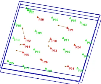
Figure 2 . GCP (green) and Check Points (red) distribution
The final accuracy has been calculated using 10 additional ground check points.
Mean Std. Dev RMS
X(m) -1.67 1.52 2.25
Y(m) 0.64 1.90 2.00
H(m) 1.26 2.34 2.66
Table 2. Results of the accuracy test over the Check Points
This check yields results comparable with other authors’ (d’Angelo 2013, Zhang et al. 2014) It must be noted, though, that a simultaneous adjustment of the RPCs for each image in the dataset (Backward, Forward, Nadir and Multispectral) has been obtained, due to the lack of coregistration between the Multispectral image and the Nadir image. This fact poses a significant challenge in the pansharpen process compared to other satellite sensors, as described in section 2.3.
2.2 DSM Generation
A DSM of 5m grid spacing was generated with Trimble’s Match-T/DSM software (version 5.7.1) using the estimated RPC of the stereo triplet. The DSM quality was analyzed in different areas (see Figures 1, 3 and 4):
(1)a 35km x 30km wide area excluding most of the clouds, (2)a 4km x 2km wide mountainous area,
(3)a 1.3km x 0.5km wide open area including
(4)a 2 hectare big area free of buildings and vegetation.
ICGC’s LiDAR DTM of Catalonia of 2m grid spacing and 15cm accuracy has served as a reference except for area (2), where a DSM was used deduced from the original LiDAR point cloud. The statistical results of the differences between the automatically generated DSM and the LiDAR reference surface are listed in Table 3. After generation, the DSM was neither manually edited nor filtered.
Test area Mean RMS Sigma Min Max
1 2.6 4.5 3.6 -45.8 44.5
2 -0.4 3.0 2.9 -34.8 43.7
3 -1.2 2.5 2.2 -14.3 7.7
4 0.3 0.6 0.6 -1.2 2.0
Table 3. Statistics of height differences between generated DSM and LiDAR reference
Test area 1 covers an area of approximately 1000km2 (40% of the image) and excludes most of the clouds located in the Southern parts. The statistical values confirm a global DSM RMS error better than 4.5m, which includes some blunders mainly caused by remaining clouds and also systematic height differences between the created DSM, representing the visible surface, and the reference DTM, representing the bare Earth without vegetation and manmade objects. These systematic differences explain the mean height offset of 2.6m between the DSM and the DTM. The obtained sigma of 3.6m corresponds approximately to 1 GSD of the oblique viewing images.
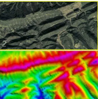
Test area 2 is located in a 4km x 2km wide mountainous region with a maximum elevation difference of 250m (see Figure 3). Using a DSM as reference surface the mean height offset becomes insignificant and, consequently, the obtained RMS error is smaller indicating a DSM accuracy of 3m.
Test area 3 includes no buildings, only little vegetation and a moderate height relief with a maximum elevation difference of 70m. Here the obtained accuracy is 2.5m, corresponding approximately to the GSD of the high resolution nadir image. The small flat test area 4 with the size of 2 hectare includes 740 DSM grid points and is completely free of vegetation (see Figure 4). Here the obtained RMS error is below 1m.
Figure 3. Above: test area 2, 4km x 2km, max. elevation difference dh: 250m. Below: Colour coded representation of the
DSM.
Figure 4. Above: test area 3, 1.3km x 0.5km, max. dh: 70m, including test area 4, 2ha, max dh: 10m. Below: Colour coded
representation of the DSM.
2.3 Pan-sharpeningand Orthoimage Generation
Pan-sharpening process has been performed taking into account the principal radiometric and geometric challenges posed by the sensor geometry. In most cases, panchromatic and multispectral bands have similar view vectors and have been collected almost simultaneously. However, random spacecraft motion between captures can cause misregistration between the panchromatic and multispectral bands. Specifically, in ZY3 sensor geometry, there is a 6 degree parallax between panchromatic and multispectral bands, making necessary to register both images by geocorrecting them separately.
Thus, in a first step, ortho images with a pixel size of 2.1m are generated from the nadir panchromatic and the multispectral image using the RPC geometry and the previously computed DTM prior to proceed with the registration process.
The pan-sharpened image quality depends mostly on the chosen algorithm. The used approach is based on the IHS methods which are often used due to their simple computation, high spatial resolution and efficiency (Baronti, 2004). However, in the case of ZY3, the final fused IHS image has a noticeable spectral distortion due to the different spectral information contained in multispectral and panchromatic bands. The blue band is not completely contained in panchromatic band, while the infrared band is partially contained in panchromatic band (see Table 3)
Band Wavelength
Panchromatic wavelength 0,5-0,8µm
Blue 450-520mm
Green 520-590mm
Red 630-690mm
Infrared 770-890mm
Table 4. ZY3 spectral bands wavelength
Therefore, an adaptive IHS method has been developed in order to approximate both bands as closely as possible, adding and subtracting to each pixel the appropriate proportion of blue and infrared respectively. Thus, the implemented approach is mostly noticeable in vegetation areas (see Figures 5 and 6) which are more influenced by near infrared band removal.
Figure 5. IHS Fused image
Figure 6. Adaptative IHS fused image The International Archives of the Photogrammetry, Remote Sensing and Spatial Information Sciences, Volume XL-3/W2, 2015
The final result corresponds to an RGB ortho pixel size of 2.10m, which has carefully bee for particular radiometric artifacts. The resu in Table 4.
Type Surf. Total (Km2)
Stripping 0.44
The perception of alternating light and dark bands. In this case, stripping has been detected along linear elements.
Blooming 0.25
Areas overexposed to light producing a white expansion around the element. The shape of the overexposed area does not typically correspond to the real element.
Color
patch 0.08
Color patches are sequences of pixels with non natural colors. Cyan color patches have always been detected in roads
Cloud 46.14 (<2% total area)
Total 46.91 Km2
Table 5. Artifact detection by type an
Regarding radiometric aspects, an addition identified showing a radiometric discontinu along the image), which might be caused b the image formation process (see Figure 7).
Figure 7. Radiometric discont
2.4 Stereo Plotting
Besides the DEM and orthophoto prod analysis on the usability of the ZY-3 imager purposes has been carried out. Different st calculated and visualized in a 3D enviro evaluate the capabilities of establishing a pr for creation and updating of topographic data
thophoto image with a een reviewed seeking esults are summarized
and extension
onal artifact has been tinuity (a straight line by a problem during
ntinuity
oducts, a qualitative ery for stereo plotting steropairs have been ironment in order to production workflow atabases.
The Nadir image has been com Forward View trying to obtain configuration has been considere mainly due to the fact that stereo p performed between images of produce difficulties in the stereosco poor accuracy in positioning resolution between Nadir and Ba shown in Figure 8 to illustrate th vision problem.
Figure8. Resolution differences be Backward/Forward i
The Backward and Forward stereop 3.5m nominal pixel, provides the b stereo plotting tests two aspec interpretation and positional accura on the ICGC catalogue that inc attributes collected in topographic d achieved a level of detail equiv transport network including paved and railways, and also for hydrogra to model the terrain as break l equivalent to 1:50000 scale for se and other constructions for exampl or tanks.
The positional accuracy has achiev 2,5 m in X,Y and H, excludin constructions, because the poor d due, again, to blooming and low these elements the achieved accur scale of 1:25000, but it is slightly for 1:50000 scale. Figure 9 shows data.
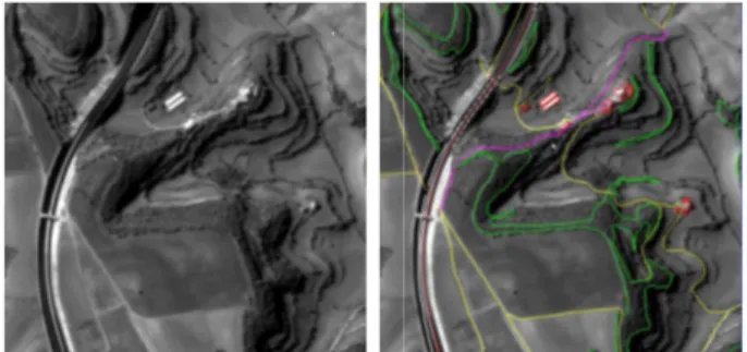
Figure 9. Example of data compi Forward stereopair. Left: Original vector data including paved roads paths (yellow), embankments (w buildings (regular polygons in red).
ombined with the Backward/ ain the best resolution. This ered as having low usability, o plotting operations have to be f different pixel size, which scopic vision, visual fatigue and g and measuring. Different Backward/Forward images are the reason of the stereoscopic
between Nadir image (left) and rd images (right).
eopair, with a configuration of a e best Base-Height ratio. In the pects have been considered, uracy. For interpretation, based includes the features and the ic databases, the recognition has uivalent to 1:25.000 scale for ed und unpaved roads, footpaths graphy, vegetation and elements lines; and a level of detail settlement, including buildings ple walls, fences, towers, pipes
ieved the equivalent to 1:25000, ding the buildings and other r definition of sharp elements w contrast of the images. For curacy is not equivalent to the tly better than the 10m defined ws an example of the compiled
piled using the Backward and al image. Right: Superimposed ds (red), unpaved roads (violet), (white), forests (green) and d).
The lack of multispectral data in the stereopairs constitutes a general drawback, since color provides valuable information during data capture. This limitation affects the proper photointerpretation of the different terrain characteristics and introduces additional difficulties in the classification of some features, for example in the distinction between paved and unpaved roads.
3. CONCLUSIONS
The first China’s civil high-resolution stereo mapping satellite, the ZY-3A, contributes to the current availability of satellite imagery for stereo mapping purposes.
The three-camera system at two different resolutions enables three-fold along track stereo capabilities, establishing more stable geometric conditions compared to other high-resolution satellites using the same sensor for stereo data capture from different orbit positions or even different orbits.
The obtained overall accuracy of the automatically derived DSM is approximately 3m. In moderate and flat terrains higher accuracies in the order of 2.5m and better can be achieved. Therefore, ZY-3A imagery is indicated to generate satellite orthophoto at scale 1:25 000 (2.5 m GSD). The effects of deformations observed in the final orthophoto are equivalent to other satellites with similar sensor configuration. However, the nature of some radiometric artifacts inherent to the sensor needs further analysis to properly correct their effects during the orthophoto generation process.
In terms of stereoplotting, a positional accuracy equivalent to 1:25000 scale is achieved for the great majority of elements. Due to the limitations of using grey scale, poor contrast images and low resolution stereopairs, buildings and other constructions have accuracies slightly better than the equivalent to 1:50000 scale. It must be taken into account that the imagery was captured in November 15 with low solar elevation. ICGC’s experience has demonstrated that other high-resolution satellites present the same effects when dealing with winter imagery.
The ZY-3A satellite appears on the market of high-resolution imagery as a valid data source especially for raster applications. The planned launch of ZY-3B will include significant improvements like 2.1m spatial resolution for all three panchromatic cameras and full alignment of the multispectral and the high resolution nadir view. It will allow enhancing the exploitation capabilities of the colored high-resolution imagery for DSM and orthophoto generation as well as for stereoplotting.
REFERENCES
Alparone, L., Baronti S., Garzelli A., and Nencini F., 2014. a global quality measurement of pan-sharpened multispectral imagery, In: IEEE Geoscience and Remote Sensing Letters, 1(4), pp. 313–317
d’Angelo, P., 2013. Evaluation of zy-3 for dsm and ortho image generation, In: International Archives of the Photogrammetry, Remote Sensing and Spatial Information Sciences, Hannover, Vol. XL-1/W1 .
Zhang, Y., Zheng, M., Xiong, J., Lu, Y. and Xiong, X. 2014. On-orbit geometric calibration of ZY-3 three-line array imagery with multistrip data sets. IEEE Transactions on Geoscience and Remote Sensing, Vol. 52, no. 1.