ISSN 1546-9239
© 2010 Science Publications
Corresponding Author: Goh Li Jin, Solar Energy Research Instiute, University Kebangsaan Malaysia, National University of Malaysia, 43600 Bangi, Selangor, Malaysia
Evaluation of Single-Pass Photovoltaic-Thermal Air Collector with
Rectangle Tunnel Absorber
Goh Li Jin, Adnan Ibrahim, Yee Kim Chean, Roonak Daghigh, Hafidz Ruslan, Sohif Mat, Mohd. Yusof Othman and Kamaruzzaman Sopian
Solar Energy Research Institute, University Kebangsaan Malaysia, 43600 UKM Bangi, Selangor Darul Ehsan, Malaysia
Abstract: Problem statement: Photovoltaic solar cell generate electric by receiving sun light or solar irradiance. But solar cell received heat from solar irradiance as well and this will reduced the efficiency of the solar cell. The heat trap at the solar photovoltaic panel become waste energy. Approach: The solution for this was by adding a cooling system to the photovoltaic panel. The purpose of this study was to cool the solar cell in order to increase its electrical efficiency and also to produce heat energy in the form of hot air. Hot air can be used for drying applications. A single pass PVT with rectangle tunnel absorber has been developed. The rectangle tunnel acted as an absorber and was located at the back side of a standard photovoltaic panel. The dimension of the photovoltaic panel was 120×53 cm. The size of the rectangle tunnel was 27 units of tunnel bar with the size of 1.2×2.5×120 cm (width×tall×length) and 12 units with 1.2×2.5×105.3 cm (width×tall×length). The rectangle tunnel was connected in parallel. The PVT collector has been tested using a solar simulator. Results: Electrical efficiency increased when the solar cell was cool by air flow. Solar photovoltaic thermal collector with rectangle tunnel absorber has better electrical and thermal efficiency compared to solar collector without rectangle tunnel absorber. Photovoltaic, thermal and combined photovoltaic thermal efficiency of 10.02, 54.70 and 64.72% at solar irradiance of 817.4 W m−2, mass flow rate of 0.0287 kg sec−1 at ambiant temperature of 25°C respectively has been obtained. Conclusion: The hybrid photovoltaic and thermal with rectangle tunnel as heat absorber shows higher performance compared to conventional PV/T system.
Key words: Photovoltaic thermal, rectangle tunnel absorber, thermal efficiency
INTRODUCTION
Efficiency of solar cell will drop when the temperature of it increases. The efficiency of the system will lose about 0.3% when cells temperature increased by 1°C (Kemmoku et al., 2004). Air can be used to cool the surface temperature of the photovoltaic panel. The air will pick up the surface heat and can be used for domestic of application including drying and other industrial process heat application.
A special type of solar collectors was design to collect electric energy and thermal energy simultaneously known as Photovoltaic-Thermal (PV/T) solar collector. Solar hybrid PV/T system can generate more energy per unit area compared to system of solar panel and thermal collector separately side by side (Charalambous et al., 2007). The purpose of using hybrid solar photovoltaic-thermal system is to prevent the electrical efficiency to drop and to collect thermal
energy in water or air as heat carrier. The first photovoltaic-thermal hot air collector application was tested at Solar Test House in Institute of Energy Conversion, University of Delaware at 1973 (Grag, 1982).
Fig. 1: Fabricate ducting
Single pass solar collector with open channel absorber has been studied by earlier researcher (Sopian et al., 1996; Prakash, 1994). The double pass solar collector with upper and lower channels has been fabricated by other researchers (Bhargava et al., 1991; Cox and Raghuraman, 1985). Comparison of single pass and double pass collector has been done and double pass solar collector shows better performance (Hegazy, 1999). Further research has been conducted by combining heat conductor into solar collector such as v-groove, porous media and fins (Othman et al., 2006; 2007). Purpose of adding heat conductor into solar collector was to enhance the heat extraction of collector and thus increase the efficiency of the collector. In this study, rectangle tunnel absorber is added into the photovoltaic thermal collector as heat conductor.
A PV/T solar collector by combining photovoltaic panel and rectangle tunnel absorber as heat conductor was fabricate and tested in this experiment. A PV/T combined single pass solar photovoltaic with rectangle tunnel system. Using single pass system instead of double pass system was to avoid using large amount of area. This design was to maintain the electrical efficiency of the solar panel and to produce hot air by extract heat from solar panel.
The objective of this study was to study that electrical efficiency and thermal efficiency of the photovoltaic thermal collector increased after adding rectangle tunnel absorber to the single pass solar collector system. Different mass flow rates have been tested on the collector to observe the effect of mass flow rate to the efficiency of collector.
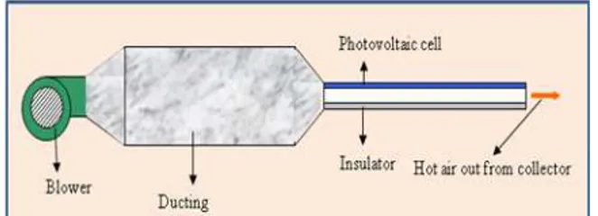
Figure 1 above shows fabricating of ducting for air flow connecting blower and solar collector. Figure 2 shows the rectangle tunnels design as heat conductor and the rectangle tunnels were placed below solar photovoltaic panel as shown in Fig. 3. An Insulator was place under rectangle tunnels to prevent heat loss from solar collector. Figure 4 and 5 show diagram of single pass solar collector system connecting blower, ducting and solar panel with rectangle tunnels.
Fig. 2: Tunnels design
Fig. 3: Solar Photovoltaic thermal air collector
Fig. 4: Connect ducting to blower and photovoltaic thermal collector
Fig. 5: Single pass solar collector system
MATERIALS AND METHODS
Experiment set up: A solar panel model of SHARP NE-80E2EA which can produce 80 W power when tested under 1000 W m−2 solar irradiance and room temperature of 25°C was prepared. 27 units of rectangle tunnel bars with the size of 1.2×2.5×120 cm (width×tall×length) and 12 units with 1.2×2.5×105.3 cm (width×tall×length) was prepared. The tunnel bars was placed at the back surface of solar panel as heat conductor. The solar panel was insulated with polyethylene to prevent heat loss. Ducting is design and fabricates to connect a blower to the photovoltaic air collector. The solar PVT collector was tested under 23 simulator halogen lamps. Regulators were used to control the brightness or solar irradiance from simulation lamps. Heaters made of 2 halogen lamps were placed inside the ducting to stabilize air temperature that going into the collector.
Experimental procedures: The experiment was run under 2 different solar irradiance values. Each solar irradiance was tested with 5 different mass flow rates. The photovoltaic thermal collector was tested with and without rectangle tunnel to compare the different. Solar irradiances from simulation lamps were set to 385.2 and 817.4 W m−2. Mass flow rates were set to 0.0110, 0.0287, 0.0409, 0.0552 and 0.0754 kg sec−1. The test
was run by setting the solar radiation to certain power and flow the air through the solar collector and slightly increase the mass flow rate for 5 times and collect data for each mass flow rate. Data like current, I (A), voltage, V (Volt), short circuit current, Isc (A) dan open
circuit Voltage, Voc (Volt) and Temperature, T (°C) is
measure every 90 min. Data collected was used to determine the electrical efficiency and thermal efficiency of both collectors.
A pyranometer was used to determine solar irradiance. Multimeter was used to collect data like current, I (A), Voltage, V (Volt) and Temperature, T (°C). J type thermocouples were connected to multimeter as a temperature indicator. Ananometer DTA 4000 used to determine the air flow velocity in the solar collector.
RESULTS AND DISCUSSION
The purpose of this experiment was to improve the cooling system by carring out as much heat as possible from solar photovoltaic PVT collector made for this experiment. So, this experiment was to increase both the electrical and thermal efficiency.
Air flow mass can be calculate from the equation below:
m = ρAVav (1)
Air flow mass, m was needed to calculate the thermal efficiency of the PVT system. Density, ρ, area of air drain input, A was standard value in this experiment. Air velocity, Vav was determine using
voltage regulator and blower.
Isc dan Voc can be achieve from connection of
circuit directly from multimeter to solar panel. While Im
dan Vm can be achieve from connection of circuit by
connect solar panel to Voltmeter and then Ampmeter while connect a Reostat, R parallel to that Voltmeter. Where Im and Vm were from power maximum, Pm.
Power, P was the result of current, I times voltage, V:
Pm = Im Vm (2)
Performance of the system PVT can be seen from electrical and thermal efficiency. Electrical efficiency,
πel and thermal efficiency, πth was shown as below:
m m el
c I V
100% A S
×
π = × (3)
p o i th
p mC (T T )
100% A S
−
π = × (4)
Error analysis: Every apparatus have their limitation of precise when collecting data. This makes the apparatus have their own error and this error will affect the result of calculation. An equation to calculate error was needed when the equation contain 2 values or above with error. Differentiation can be used to calculate error equation.
For mass flow rate’s equation, which was density of air X area of air flow X air velocity. Density of air can be excluded from error equation because it’s a constant value. Equation to calculate error for mass flow rate was shown below:
A V
m m
A V
δ δ
⎡ ⎤
δ =⎢ + ⎥
⎣ ⎦ (5)
For electrical efficiency, which was current maximum X voltage maximum divided by cells surface area X solar irradiance. All this values was calculated by apparatus and so had errors.
[
] [
]
(Im Vm) Im (Vm) Vm (Im)
δ × = × δ + × δ (6)
[
] [
]
(Ac S) Ac (S) S (Ac)
[
] [
]
2Ac S) (lm Vm) (lm Vm) (Ac S) el
[Ac S]
× δ × − × δ ×
δπ =
× (8)
For thermal efficiency equation, specific heat for air, Cp was a constant value and not determined using any apparatus. Thus, Cp can be ignored when calculating error for thermal efficiency. Below are the data needed for thermal efficiency error calculation:
m T th
Ap S
× Δ π =
× (9)
[
] [
]
(m T) m ( T) T (m)
δ × Δ = × δ Δ + Δ × δ (10)
[
] [
]
(Ap S) Ap (S) S (Ac)
δ × = × δ + × δ (11)
[
] [
]
2
(Ap S) ( T) ( T) (Ap S) th
[Ap S]
× δ π × Δ − π × Δ δ ×
δπ =
× (12)
The error for mass flow rate was 0.0052 kg sec−1 for example (754±52)×10-4 kg sec−1. Error for electrical efficiency around 4.04-4.43% and for thermal efficiency was around 0.28-0.49%. Error for thermal efficiency was lower than electrical efficiency and it’s because the mass flow rate used in thermal calculation had smaller error compare to current and voltage used in electrical.
Figure 6 shows that surface temperature of photovoltaic panel drops when increasing the mass flow rate. Solar photovoltaic thermal collector with tunnel has lower temperature compare to collector without tunnel. From Fig. 6, panel’s temperature can be cooled from 13°C to 20°C depend on the mass flow rate. This shows that collector with tunnel can help carry more heat out of the solar collector.
Figure 7 shows I-V curve for collector with and without tunnel at 0.0552 kg sec−1 mass flow rate and solar radiation of 817.4 W m−2. Figure 7 shows that collector with tunnel has higher power maximum compared to collector without tunnel. Collector with tunnel have power maximum of 22.45 W and collector without tunnel has only 20.66 W.
From Fig. 6 and 7 can be noticed that photovoltaic cells that have lower temperature can archived higher open circuit voltage (Voc), short circuit current (Isc) and
also power maximum (Pm). This result shows that lower
temperature of photovoltaic cells can increase the power output and increasing in cells temperature will lower the power output and the efficiency as well.
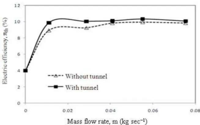
Figure 8 shows the electrical efficiency increase when the mass flow rate increases. But the electrical
efficiency only increase to certain mass flow rate and then archived static stage after 0.07 kg sec−1 of mass
flow rate. Photovoltaic thermal collector with tunnel shows better efficiency in electrical compare to collector without tunnel because solar panel has lower temperature for solar collector with tunnel. Electric efficiency for solar collector with tunnels can reach as high as 10.31% at 0.05 kg sec−1 of air mass flow rate.
Fig. 6: Comparison of panel’s temperature
Fig. 7: I-V curve of system with and without tunnel
Fig. 9: Thermal efficiency of both collectors
Fig. 10: Thermal efficiency over temperature different
Thermal efficiency over mass flow rate above shows about the same increase with electrical efficiency but only has much higher efficiency. Thermal efficiency for collector without tunnel reaches steady stage when the mass flow rate over 0.04 kg sec−1. For collector with tunnel, thermal efficiency reached steady stage after 0.07 kg sec−1 of mass flow rate. From Fig. 6 and 10 above, the thermal efficiency can increase about 30% if temperature of photovoltaic module drops about 20°C.
Figure 9 shows comparison of thermal efficiency for 2 different solar collectors. Compare to electric efficiency, thermal efficiency shows big different between solar collector with and without rectangle tunnels. Thermal efficiency for collector with rectangle tunnels can archive about 75.16% but for collector without rectangle tunnels, only 44.4% of thermal efficiency at 0.07 kg sec−1 of mass flow rate.
Figure 10 and 11 show the design curve of efficiency over temperature difference for all the solar irradiance and mass flow rate set in this experiment. The area inside the square shows all the possible efficiency for which temperature difference in the range of mass flow rate and solar irradiance set.
Fig. 11: Overall efficiency over temperature different Figure 10 shows the thermal efficiency of the PV/T at temperature difference, ∆T (To-Ti), solar irradiance
levels and mass flow rates. For instance, at solar irradiance level of 800 W m−2 and mass flow rate of 0.01 kg sec−1 the ∆T is around 11.5°C and thermal efficiency is around 25%.
Figure 11 shows the total efficiency versus temperature different of the collector with rectangle tunnels. The graft of Fig. 11 shows that total efficiency can reach about 85% when the temperature different is 6°C in condition of 0.08 kg sec−1 mass flow rate and 800 W m−2 solar irradiance.
Objective of this experiment was archived by increased the electric efficiency by adding rectangle tunnels as heat conductor to the solar photovoltaic panel. Higher hot air output also gain from the solar collector with rectangle tunnels. Result from this experiment compared to research on flat plate solar air collector has also shows better performance in both electric and thermal efficiency (Solanki et al., 2009).
CONCLUSION
Recommendations: Recommendations for this experiment were that minimize the error of the apparatus used. The solar collector can be change to double pass collector to compare its performance with single pass system. Rectangle tunnel absorber can be change to fin or porous media to compare the performance. System collecting data using computer called data logger can be used to collect data like for more precise data.
ACKNOWLEDGMENT
The researcher is grateful to have supports from Prof. Kamaruzzaman, Prof. Yusof, Dr. Hafidz and also financial support from SERI, UKM.
REFERENCES
Amir, E.J., K. Grandegger, A. Esper, M. Sumarsono, C. Djaya and W. Muhlbauer, 1991. Development of a multi-purpose solar tunnel dryer for use in humid tropics. Renew. Energy, 1: 167-176. http://cat.inist.fr/?aModele=afficheN&cpsidt=5240 314
Charalambous, P.G., G.G. Maidment, S.A. Kalogirou and K. Yiakoumetti, 2007. Photovoltaic Thermal (PV/T) collectors: A review. Applied Therm. Eng.,
27: 275-286. DOI: 10.1016/J.APPLTHERMALENG.2006.06.007
Cox, C.H. and P. Raghuraman, 1985. Design considerations for flat-plate-photovoltaic/thermal collectors. Solar Energy, 35: 227-241. http://www.osti.gov/energycitations/product.biblio. jsp?osti_id=6312358
Bhargava, A.K., H.P. Garg and R.K. Agarwal, 1991. Study of a hybrid solar system-solar air heater combined with solar cells. Energy Convers.
Manage., 31: 471-479. http://eprint.iitd.ac.in/dspace/handle/2074/2535?mo
de=full
Grag, H.P., 1982. Treatise on Solar Energy: Fundamentals of Solar Energy. John Wiley and Sons, Chicester, ISBN: 13: 978-0471101802, pp: 587.
Hegazy, A.A., 1999. Comparative study of the performances of four photovoltaic/thermal solar air collectors. Energy Convers. Manage., 41: 861-881. DOI: 10.1016/S0196-8904(99)00136-3
Jayaraman, K.S. and D.K. Gupta, 1995. Drying of Fruits and Vegetables. In: Handbook of Industrial Drying, Mujumdar, A.S. (Ed.), Vol. 2, Marcel Dekker Inc., ISBN: 0824796446, pp: 643-690. Kemmoku, Y., T. Egami, M. Hiramatsu, Y. Miyazaki
and K. Araki et al., 2004. Modelling of module temperature of a concentrator PV system. The
University of Sydney. http://www.physics.usyd.edu.au/app/solar/research/
Syracuse/pdf/19thEUPVSEC_5BV-2-40.pdf Othman, M.Y.H., K. Sopianab, B. Yatima and W.R.W.
Daud, 2006. Development of advanced solar assisted drying system. Renew. Energy, 31: 703-709. DOI: 10.1016/J.RENENE.2005.09.004 Othman, M.Y., B. Yatim, K. Sopian and M.N. Abu Baker,
2007. Performance studies on a finned double-pass Photovoltaic-Thermal (PV/T) solar collector.
Desalination, 209: 43-49. DOI:
10.1016/J.DESAL.2007.04.007
Prakash, J., 1994. Transient analysis of a photovoltaic-thermal solar collectors for co-generation of electricity and hot air/water. Energy Convers.
Manage., 35: 967-972. http://cat.inist.fr/?aModele=afficheN&cpsidt=3339
217
Solanki, S.C., S. Dubey and A. Tiwari, 2009. Indoor simulation and testing of Photovoltaic Thermal (PV/T) air collectors. Applied Energy, 86: 2421-2428. DOI: 10.1016/j.apenergy.2009.03.013
Sopian, K., K.S. Yigit, H.T. Liu, S. Kakac and T.N. Veziroglu, 1996. Performance analysis of photovoltaic thermal air heaters. Energy Convers.
Manage., 37: 1657-1670. http://cat.inist.fr/?aModele=afficheN&cpsidt=3084