High Temperature Erosion-oxidation Resistance of Thermally Sprayed Nanostructured
Cr
3C
2-25(Ni-20Cr) Coatings
Cecílio Alvares da Cunhaa, Olandir Vercino Correaa, Isaac Jamil Sayegb,
Lalgudi Venkataraman Ramanathana*
Received: October 09, 2015; Revised: March 01, 2017; Accepted: April 21, 2017
This study reports the high temperature erosion-oxidation (E-O) behavior of conventional and nanostructured Cr3C2-25(Ni-20Cr) coatings prepared by high velocity oxygen fuel (HVOF) spraying. As-received and nanostructured Cr3C2-25(Ni-20Cr) powders with mean crystallite sizes of 145 nm
and 50 nm respectively, were used to prepare 120 - 200 μm thick coatings on AISI 310 samples. The E-O behavior of the coatings prepared with the as-received (AR) and nanostructured (NS) powders
was determined as weight change in a custom designed rig at room temperature, 450, 700 and 800 ºC.
The Vickers microhardness, Young’s Modulus and fracture toughness of the AR and NS coatings were determined, and the NS coatings exhibited higher values compared with the AR coatings. The E-O resistance of the NS coating was higher than that of AR coating at all temperatures, and particularly at 800 ºC. The increase in E-O resistance of the NS coatings is due to its superior mechanical properties
as well as to the presence of some heterogeneities in the AR coatings. The E-O mechanisms of both types of the coatings are discussed, with special attention to that at high temperatures. The results suggest that at 800 ºC the E-O process is controlled by erosion of the oxide.
Keywords: Nanostructured coating, Chromium carbide, Erosion-oxidation, Hardness, Thermal spraying
* e-mail: [email protected]
1. Introduction
In many engineering ields there has been a steady increase
in demand for materials with enhanced physical properties.
In this context, the pioneering work of Benjamin et al1,2 that
established the process which became globally known as
“Mechanical Alloying” has produced materials with superior mechanical properties, and this process has since evolved
considerably. Researchers like Gleiter3, Berringuer4, Kock5,6,
Hellstern7, Lavernia8,9 and Suryanarayana10 among others who
have worked in this area, conirmed the superior mechanical
properties of nanocrystalline materials compared with their
conventional counterparts. In the last few decades, several kinds of coatings have been developed using nanocrystalline
materials. Chromium carbide based coatings are used to protect components exposed to severe conditions in a number of industries11-14. A variety of techniques have been
used to prepare chromium carbide based coatings and the high velocity oxygen fuel (HVOF) process is widely used, as it produces smooth, low porosity, dense and adherent
coatings, without altering signiicantly the integrity of the
carbide particles11,15,16. Brandt17 investigated the efects of
diferent HVOF spraying parameters on the fatigue resistance
of samples coated with Cr3C2-NiCr powders; Lavernia18-20
conducted several investigations in this area, ranging from synthesis of nanostructured Cr3C2-25(Ni-20Cr) coatings to the development of nanocrystalline structures using
cryogenic environment; He and Schoenung11 performed a
comprehensive study of nanostructured coatings produced by HVOF, with emphasis on nanostructured WC-Co and Cr3C2-25(Ni-20Cr) powders; Guilemani et al.21 conducted
microstructural characterization of Cr3C2-NiCr coatings
produced by HVOF, besides investigating the efects of
thermal cycling and extended isothermal treatment on the adhesion properties of as-coated and thermally treated samples; Roy et al.22 also compared the microstructure
and mechanical properties (hardness, elastic modulus and fracture toughness) of coatings produced with as-received and nanostructured Cr3C2-25(Ni-20Cr) powders. Overall,
these and many other investigations have shown that speciic
properties of nanostructured materials are better than those of their conventional counterparts23-28.
It is important to note that coatings prepared with
nanocrystalline materials usually exhibit higher hardness and strength when compared with coatings prepared with corresponding conventional materials. Despite the fact that WC-Co coatings are harder than Cr3C2-NiCr coatings,
a Instituto de Pesquisas Energéticas e Nucleares - IPEN-CNEN-SP, Av. Prof. Lineu Prestes, 2242,
Cidade Universitária, São Paulo, SP, Brazil
the use of the former at temperatures higher than 450 ºC has caused some concern regarding decarburization and consequent decrease in mechanical properties. However Cr3C2-NiCr coatings are more stable at high temperatures and are frequently used at temperatures of the order of 800 or 900 ºC. Nevertheless, prolonged use of this coating under such severe conditions also causes degradation of its properties. Hence, determination of the mechanical properties, erosion behavior and oxidation resistance of these coatings
have been the subject of many studies.
As it is an established fact that the interaction of the two processes, erosion and oxidation, usually leads to increased degradation of the material, understanding the mechanisms of erosion-oxidation (E-O) of metals and alloys is of importance. One of the early studies in this area was
performed by Hogmark et al.29, in which E-O interactions
were described in terms of regimes that supposedly prevailed. Further, Kang et al.30, and Sethi et al.31 suggested other
classiications of E-O regimes. Later Stephenson et al.32-34,
studying the erosion of turbine blade materials showed that the predominant mode of material loss was by removal of oxide scales. They also found that the erosion behavior of
Ni based alloys difered signiicantly at 700 and 850 ºC, depending on oxide scale thickness and plasticity (lower temperatures and thicker oxides favouring brittle erosion behavior of the scale). In the early 90’s, Sundararajan35
deined the following regimes for the E-O process: a) erosion of the metal; b) erosion afected by oxidation and c) erosion of the oxide. Stack and Stott36 developed a model to establish
the boundaries on erosion corrosion maps, and these maps showed transitions through the regimes as functions of the
main erosion-corrosion variables. It should be noted that
while some researchers37 believe that erosion of metals and
alloys by solid particles at high temperatures is the result
of diferent mechanisms of interaction between erosion
and oxidation, depending fundamentally on the nature,
thickness, adhesion and morphology of the oxide, others38
support the idea that the mechanisms of E-O also depend on the properties of the erodent particles (size, hardness, shape, etc.), the characteristics of the system that is being used (velocity and impact angle), as well as the environment (temperature and partial pressure of the gases).
Among the above mentioned studies, Sundararajan and
Roy39 presented a comprehensive study of the behavior of
metallic materials at room and elevated temperature, when submitted to solid particle erosion. Their study presented not only a brief review of the main parameters related to erosion at room and high temperature, but also the mechanism that governed the E-O process. A number of investigations have been carried out about the E-O behavior of coatings produced by HVOF and similar processes13,40-47. Further,
Roy et al.22 compared properties of coatings produced with
nanostructured and as-received Cr3C2-25(Ni-20Cr) powders and Matthews et al.48-50 studied the high temperature erosion
of thermally sprayed Cr3C2-NiCr coatings. Additionally, most
solid particle erosion studies have used either luidized beds, with particle impact velocities in the range 1 to 6 m/s or jet
nozzles that achieve very high impact velocities of around 200 m/s to simulate erosion conditions in gas turbines50.
In this investigation the E-O behavior of HVOF sprayed
Cr3C2-25(Ni-20Cr) coatings at temperatures up to 800 ºC and with erodent impact velocities of 19 m/s was determined.
Finally, as already mentioned, the fatigue and scuing resistance, as well as the inluence of thermal spray parameters
on corrosion, friction and abrasive wear resistance of
chromium carbide coatings have been the subject of other
studies17,51-53. Hence, taking into consideration the importance
of mechanical properties on the behaviour of coatings, in
this investigation the Vickers microhardness, the elastic
modulus and the fracture toughness of the coatings were determined, in order to understand better the E-O behavior of the coatings.
2. Materials and Methods
A high energy ball milling device (ZOZ) was used to
mill Cr3C2-25(Ni20Cr) powders from Oerlikon METCO
(WOKA 7202). The stainless steel vessel of this mill had an approximate volume of 2000 cm3. Chromium-steel balls
4.7 mm in diameter were used with gaseous nitrogen as the milling medium. The main powder milling parameters were
400 rpm, ball to powder ratio 10:1 (1 kg of steel balls was
used for 100 g of powder to be milled) and milling time of 8 h. Details about powder preparation and powder characteristics can be found elsewhere13. The Cr
3C2-25(Ni20Cr) powder
was high energy milled to obtain nanocrystalline powder with average particle and crystallite sizes of 20µm and 50 nm, respectively. The particle size was determined in a
CILAS equipment[1], while the crystallite size of the milled
powder was determined by x-ray difraction analyses, using a Rigaku Multilex x-ray difractometer54-56. This was carried
out using the Rietveld method for lattice reinement57-60. The
details of crystallite size determination can be found in the following studies11,13.
The powders in the as-received (AR) and milled condition
were used to produce coatings 120 to 200 μm thick on AISI
310 stainless steel sheet samples (50 x 20 x 2 mm) using a
Sulzer Diamond Jet HVOF thermal spray equipment. The deposition parameters were: oxygen pressure - 1034 kPa; oxygen low rate - 490 l/min; fuel pressure - 517 kPa; fuel low rate - 70 l/min; air pressure - 517 kPa; air low rate - 800 l/min; carrier gas pressure - 1034 kPa; carrier gas low rate 30
l/min; powder feed rate - 0.35 g/s; spray distance - 250 mm.
The surfaces and cross-sections of the AR and NS coatings
were examined in a JEOL JSM6701F scanning electron
microscope coupled to an energy dispersive spectrometer
system. Vickers microhardness of the coatings (AR, NS and NS coating oxidized at 800 ºC for 32 hours) was determined at room temperature in a test device (Shimadzu) using load of
300 g. The microhardness of each specimen was the average value of at least 10 measurements. Higher load (500 g) was
also used to provoke cracks at the edge of the indentations
to determine the fracture toughness of the material. Further, an instrumented microhardness test device (Fischerscope)
using a 500 mN load, was used to determine the Young’s modulus. Based on the microhardness, the elastic modulus values and the lengths of the cracks emanating from the
hardness indents, fracture toughness of the coatings were determined22,61,62.
The erosion-oxidation (E-O) tests were performed in a
rig where coated samples were rotated through a luidized
bed of alumina particles (210 µm) inside a furnace63,64. The
E-O tests were carried out for 5 hours at room temperature, 450, 700 and 800 ºC. Most of the E-O tests were carried out with erodent impact velocity of 19 m/s and some tests at 800 ºC were also carried out with erodent impact velocity of 10 m/s. Overall, 92 samples were E-O tested. The samples
were weighed in a precision instrument (Shimadzu) before
and after the tests to determine E-O resistance. The surface roughness of the samples was also measured with a Mitutoyo
SJ-301 Surface Roughness Tester, before and after the test,
at identical regions (9 positions per sample).
3. Results and Discussion
3.1. Microstructure and mechanical properties of
the coatings
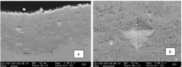
Cross-sectional micrographs of the coatings prepared with
the AR and NS powders are shown in Figure 1. Overall, the
coatings revealed a uniform structure with good distribution of the carbides in the binder phase and the typical lamellar structure often observed in coatings produced by the HVOF process. Further, the coating bonded well with the substrate
and its thickness varied slightly, depending on the number
of “passes” during the coating process. The nanostructured
(NS) coatings were more homogeneous, dense and revealed the iner carbides uniformly distributed in the NiCr matrix
(Figures 1a and 1b). On the other hand, the as-received (AR) coatings were not quite homogeneous and dense, but revealed a reasonably uniform distribution of the coarser carbides in the NiCr matrix. The lamellar structure in the AR coatings was less evident and many discontinuities such as pores and
embedded oxide ilms were seen (Figure 1c and 1d). It is important to note that the oxide ilms which form between
“splats” during the coating process - quite distinct from the oxide layer that forms on the surface upon exposure to high
temperatures - weaken the microstructure in terms of the
erosion process, given that the regions close to the oxide
ilms are more susceptible to de-cohesion during impact of
erodent particles.
Regarding mechanical properties of the coatings,
the Vickers microhardness (indents shown in Figures 2a and 2b) and Young’s modulus measurements (performed
in an instrumented microhardness test device, using a 500 mN load, that allowed determination of the elastic modulus of the material), were made on polished cross sections of specimens extracted from the coated samples. Using data obtained from these measurements, the fracture toughness
of the coatings was determined using Roy et al’s22 approach,
which was originally based on the method developed by Nihara et al61 for brittle solids and shown in equation (1),
that used the lengths of the cracks emanating from the microhardness indents (Palmqvist indentation technique61). Figure 1. (a) Backscattered electron image showing the microstructure
of nanostructured Cr3C2-25(Ni20Cr) coating. Note the relatively
uniform and dense structure, as well as good bonding with the substrate. The lamellae aspect of the coating is typical of structures produced by the HVOF process; (b) detail of (a) illustrating the distribution
of ine carbides in the Ni20Cr matrix.; (c) backscattered electron
image showing the microstructure of as-received Cr3C2-25(Ni20Cr)
coating. Note the presence of some heterogeneities; (d) detail of
(c) showing pores as well as some oxide ilms between the splats.
Where: FT is fracture toughness, KIC - stress intensity
factor, E - Young’s modulus, H - hardness, P - load and l - crack length.
Table 1 shows the Vickers microhardness, Young’s
modulus and fracture toughness of the coatings. The hardness
and Young’s modulus of the NS Cr3C2-25(Ni20Cr) coatings
were approximately 30% higher than that of the coatings prepared with AR powders. Additionally, the fracture toughness
of the NS coatings was approximately 36% higher than that of the AR coatings. Published literature11,65 attributes
the improved mechanical properties of NS coatings to its nanocrystallinity (intrinsic higher hardness of NS phases), as
well as to microstructural uniformity, caused by the process to
.
( / )
( )
FT
K
0 0123
E
/H
/P
1
/1
IC
2 5 1 10 1 2
synthesize nanocomposite feedstock powder. It is important to note that microstructural diferences between the two types
of coatings, as already mentioned in11, is also related to the
higher volume fraction of carbide phase in the NS coatings
compared with that in the AR coatings, which contributes
to the microstructural uniformity of the NS coating. The
lower amount of carbide phase in the AR coatings is due to it being lost from bouncing of micro-sized carbides (coarse
carbides) from the AR feedstock during HVOF spraying. In the NS coatings, most of the nano-sized carbides, which are
almost enveloped by the NiCr matrix phase, are retained on the sprayed substrate.
precipitation of the dispersed oxide particles. Additionally, they observed that microhardness of the conventional coating increased only slightly with increase in exposure temperature,
while that of the NS coatings increased markedly. The increase in microhardness of the NS coatings was attributed to a high
density of oxide nanoparticles precipitating within the coating as the exposure temperature increased up to 800 ºC (higher degree of supersaturation).
Despite the fact that in our investigation the increase in microhardness due to exposure to high temperature was not as high as that reported by He and Lavernia, we observed the same tendency and attribute it to possible over-aging, given that we used the same test temperature, but an exposure time four times longer. Nevertheless, we consider the superior mechanical
properties of the oxidized NS coatings are related to homogeneous distribution of ine carbides and oxides in the binder phase.
3.2. The erosion-oxidation behavior of the coatings
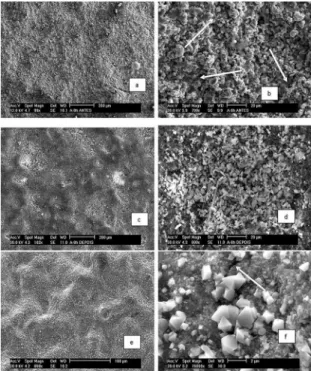
Surfaces of the AR and NS coatings revealed marked changes
after the E-O test, as shown in Figure 3. The micrographs in
Figures 3a and 3b are of the NS coating before the E-O test, while
Figures 3c and 3d show the surface of the same sample after the E-O test at 450 ºC (v=19 m/s and 5 h), revealing clear evidence of erosion of the surface. On the other hand, the micrographs
shown in Figures 3e and 3f show the surface of the NS coating
after the E-O test at 800 ºC (v=19 m/s and 5 h). Despite the fact that these samples also revealed some evidence of erosion of the surface, they appear less damaged and slightly smoother than the coating shown in Figure 3c and 3d (tested at 450 ºC). This can be attributed to the E-O regimes involved (discussed
further on), that depends on the thickness of the oxide layer.
The average surface roughness of the two types of coatings
before and after the E-O tests are shown in Table 2. It can be seen that the surface of the NS coating is smoother than that of the AR coating. This diference in surface features after the
E-O tests is probably related not only to the smoother surface
of the NS coating prior to the E-O test, but also to smoothening
of the surface by particle impact.
It is well established that Cr3C2-25(Ni20Cr) coatings (AR or
NS) oxidized for prolonged periods in air at temperatures equal
to or higher than 450 ºC form a surface layer of Cr2O3 under a thin outer layer of NiO66,67. Our results showed formation of
these oxides. However, during the E-O tests the outer NiO layer
is the irst to be removed by the erosion process and it does not
form again, as mentioned by Matthews et al.48,49,68. Figure 4
shows the Cr2O3 layer on the surface of a sample E-O tested at 800 ºC (v=19 m/s and 5 h).
Figure 2. Secondary electron micrographs of HVOF sprayed
nanostructured Cr3C2-25(Ni20Cr) coating: (a) shows uniform
structure, good bonding to substrate, smooth surface and two hardness
measurement indents; (b) detail of (a) showing cracks emanating
from the indent formed with a higher load.
Table 1. Hardness, Young's modulus and fracture toughness of the
coatings prepared with Cr3C2-25(Ni20Cr) powders.
Coating
condition HV (GPa) E (GPa)
KIC
(MPa m½)
AR 7.97 +/- 0.83 172.29 +/- 12.85 1.77
NS (AS) 10.37 +/- 1.21 223.40 +/- 12.23 2.23
NS (oxidized) 10.79 +/- 0.74 232.35 +/- 10.07 2.41
1. AS - as sprayed; NS (oxidized) - NS coating oxidized at 800ºC for 32 h.
2. At least 10 indentation were made on each specimen to determine the mean microhardness.
The efect of oxidation of the NS coating on its mechanical
properties was determined to help understand the high temperature
E-O behaviour of the coatings. In this context, the three parameters of the oxidized NS coating (hardness, Young's modulus and fracture toughness) were higher than that of the as-sprayed NS coating and corroborate well with He and Lavernia’s observations65.
In their investigation of microstructural transformations in
as-sprayed and thermally treated Cr3C2-25(Ni20Cr) coatings,
they studied the precipitation phenomenon in NS coatings using
transmission electron microscopy[2].They observed the presence
of ultraine Cr2O3 particles (average size of 8.3 nm) in the NS
Cr3C2-25(Ni20Cr) coatings exposed to elevated temperatures and attributed internal oxidation to be responsible for the
[2] He and Lavernia: "The phenomenon of supersaturation, which results in subsequent precipitation, is commonly observed in materials manufactured by non-equilibrium processes, i.e. rapid-quenching, mechanical alloying/milling and thermal spraying. In related studies, a signiicant amount of W and C was dissolved into the binder phase of WC-Co coatings, and a non-equilibrium microstructure was detected
in the as-sprayed nanostructured Cr3C2-NiCr coatings synthesized by mechanical milling and high velocity oxygen fuel (HVOF) thermal
types of coatings under diferent conditions and clearly indicates that the NS coatings performed better at all temperatures. In
tests carried out with erodent impact velocity of 19 m/s, the highest weight loss of both coatings was at room temperature
and decreased markedly with increase in temperature to 450
ºC. This is due mainly to two factors: the overall increase in hardness, as mentioned earlier, which contributes towards increase in resistance to erosion (and, consequently, reduced weight loss) and the formation of a surface oxide layer that contributes to increase in weight (reducing the weight loss from erosion). Further, at temperatures equal to or higher than 450 ºC the weight loss of the two types of coatings increased with temperature.
Figure 3. Secondary electron micrographs showing the surface of a
sample coated with nanostructured Cr3C2-25(Ni20Cr) powder (milled for 8 hours): (a) before the E-O test; (b) detail of a region in (a), showing the presence of splats on the coating surface; (c) after the E-O test (450ºC, 19 m/s, 5 hours), where damage caused by the E-O process can be seen; (d) detail of a region in (c), showing evidence of beginning of the erosion process on the coating surface; (e) after the E-O test (800ºC, 19 m/s, 5 hours). Due to relative plasticity of the
oxide at this temperature, marks of erodent particle impingement on
the oxide surface can be seen; (f) detail of a region in (e,) showing discontinuities in the oxide layer (arrow) that can eventually lead to spalling of the oxide layer under impact of erodent particles.
Table 2. Average surface roughness (Ra) of the coatings prepared with the Cr3C2-25(Ni20Cr) powders, before and after the E-O tests.
Coating condition Before (μm) After (μm)
AR 6.02 +/- 0.44 5.05 +/- 0.18
NS (AS) 3.00 +/- 0.50 2.09 +/- 0.58
AS - as-sprayed.
Figure 4. (a) Backscattered electron micrograph of nanostructured
Cr3C2-25(Ni20Cr) coating E-O tested at 800ºC (19 m/s, 5 hours). Note: the oxide layer (Cr2O3) can be clearly seen on the surface of
the eroded coating; (b) detail of the region in (a), showing that the
oxide layer has penetrated approximately 20 μm at some regions.
Figure 5 shows a compilation of all the E-O test results and illustrates the average weight changes of the coated samples.
This igure aids comparison of the E-O behavior of the two
Figure 5. Erosion-oxidation test results of samples coated with
AR and NS Cr3C2-25(Ni20Cr) powders. Tests were carried out for
5 hours at 25, 450, 700 and 800 ºC and erodent velocities of 10 and 19 m/s. Overall, 92 samples were tested and under each set of conditions, at least 4 samples. Note the improved performance of
the NS coatings at the diferent temperatures, and especially under
the condition 800ºC, 19 m/s, 5 hours when it was around 52% more erosion-oxidation resistant compared with the AR coating.
As originally stated by Levy et al.69, who investigated the
inluence of temperature (up to 900 ºC) on the erosion process of several kinds of steels, the erosion rate was constant or
decreased with increase in temperature until a certain value
(speciic for each material), and then increased rapidly with
further increase in temperature. Later, Wang and Luer14 also
reported that the erosion rates of Cr3C2-NiCr based coatings decreased with increase in temperature, in the range 25 ºC to 300 ºC, after which it increased continuously with increase in temperature. The E-O data obtained in our investigation, and shown in Figure 5, reveals a similar behavior. This suggests
the existence of a ‘critical’ temperature for the AR coating
between 450 and 700 ºC, at which the erosion-oxidation
process begins to markedly increase as temperature is increased, while for the NS coating this ‘critical’ temperature
is higher, i.e., between 700 and 800 ºC.
Poor performance of the AR coatings compared to the NS coatings at the diferent temperatures can be attributed
to the lower hardness and the presence of discontinuities
former. Further, Figure 5 shows that the weight losses of the
NS coatings at 450 and 700 ºC are quite close. This behavior can be attributed to the diferences in microhardness and oxidation rates at the two temperatures. In a previous study,
reported elsewhere70, the hardness at room temperature of the
NS coated samples tested at 700 ºC was around 20% higher than that of the NS coated samples tested at 450 ºC, indicating
that the former is more resistant to erosion. However, this higher hardness, and therefore higher resistance to erosion, is compensated by increased loss, due to the impact of
erodent particles, of a thicker and more internally stressed
Cr2O3 layer[3] at 700 ºC, compared to that formed at 450 ºC.
At 800 ºC the weight loss of the NS coating is much more signiicant than that at 700 ºC. This increased weight loss at
800 ºC can be also attributed to higher oxidation rate, which
leads to formation of a thicker oxide layer that - despite its
slightly higher plasticity at 800 ºC - has more regions which
are highly stressed and thus susceptible to crack formation
followed by spalling under continued impact of erodent particles. At regions where spalling occurs, the substrate is exposed to impact of erodent particles, increasing thus the
severity of the erosion process of the NS coating. Figures 6a and 6b show the surface of a NS coated sample that was
E-O tested at 800 ºC for 5h with erodent velocity of 19 m/s.
These igures reveal the presence of some discontinuities
in the oxide layer that can eventually lead to spalling of the oxide layer under the impact of the erodent particles.
Figures 6c and 6d show typical cracks in the surface oxide layer of another NS coated sample that was E-O tested under the same conditions mentioned above. In a similar manner, these cracks can also lead to complete removal of the oxide
layer after prolonged periods at high temperatures and with continued impact of the erodent particles.
As mentioned before, at regions where the oxide layer has spalled, the exposed coating surface undergoes erosion and this damage is believed to be caused by a micromachining mechanism, as shown in Figures 7a and 7b. The areas more susceptible to the micromachining mechanism of erosion are, apparently, the inter-splat regions, particularly ones
where long oxide ilms had formed. These regions, without
metallurgical bonding, are more susceptible to de-cohesion under the impact of erodent particles, contributing thus to deterioration of the substrate and to weight loss. On the
other hand, the weight gain of the AR and NS coatings
observed in the E-O test carried out at 800 ºC, for 5 h and erodent impact velocity of 10 m/s, is due to the higher rate
of Cr2O3 scale formation as opposed to its removal by the erodent. Overall, the weight loss data clearly indicate the
superior performance of the NS coatings. That is, higher E-O resistance of the NS coatings compared with AR coatings
exposed at the same test temperature to the same erodent impact velocity and for the same period of time.
E-O weight change data and features on the surfaces of
samples E-O tested at the diferent temperatures indicate that
the predominant E-O mechanism leading to erosion of the
substrate of both coatings (AR and NS) at room temperature
is probably micromachining[4], while the prevalent mechanism
at temperatures equal to or higher than 450 ºC is apparently spalling of the oxide layer (i.e., the E-O process is initially controlled by erosion of the surface oxide layer), followed by erosion of the substrate, similar to the regimes proposed
by Sundararajan et.al39. These regimes, as mentioned before,
as a function temperature, are: (a) erosion of the metal; (b)
erosion afected by oxidation; (c) erosion of the oxide[5].
Usually, erosion of the substrate and/or the oxide layer
results in levelling of the surface. In this investigation this is
Figure 6. Secondary electron micrographs showing the surface of
a sample coated with nanostructured Cr3C2-25(Ni20Cr) powder
(milled for 8 hours) and E-O tested (800ºC, 19 m/s, 5 hours); (a) Note as mentioned in the text, due to relative plasticity of the oxide the surface of the oxide layer presents an aspect that resembles a “sheared area” in the direction indicated by the arrow; (b) detail of image in (a) showing the presence of discontinuities in the oxide layer (see arrows) that can eventually lead to spalling of the oxide layer under the impact of the erodent particles; (c) surface of another sample after the E-O test (800ºC, 19 m/s, 5 hours); (d) detail of
image in (c) showing the presence of several cracks in the oxide layer. These cracks - after prolonged periods at high temperatures
and with continued impact of the erodent particles - can lead to complete removal of the oxide layer.
[3] This is based on the well-known phenomenon that thicker scales have higher internal stresses and thereby more prone to crack formation,
a consequence of stress relief.
[4] As is well established in the studies of erosion of metals and alloys - since the pioneering work of Finnie71,72 - hardness is one of the most important property regarding resistance of the material to the erosion process. In this case, not only the hardness at room temperature is
lower than that of the material exposed to high temperature (precipitation hardening), but also the hardness of AR coating is lower than that
of the NS coating, beyond the fact that the AR coating presents a poorer microstructure with many discontinuities, like pores and oxide ilms. [5] According to Sundararajan, when the erosion regime is controlled by oxidation, two situations can happen: a) erosion controlled
corroborated by the surface roughness data presented earlier
in Table 2. The surface of the NS coating is smoother than the surface of the AR coatings. Beyond the efect of the higher microhardness of the NS coatings on its erosion resistance,
its more regular and smoother surface[6] is also thought to
have a beneicial inluence on its resistance to erosion, at
room and at higher temperatures, particularly when the micromachining mechanism71-74 is operative.
4. Conclusions
The results obtained in this investigation show that the
NS coatings - produced by the HVOF process and using
high energy milled Cr3C2-25(Ni20Cr) powders - had better mechanical properties than the coatings produced with powders in the as-received condition. This fact, particularly the higher
hardness of the NS coating, is closely related to the higher erosion-oxidation resistance of the NS coatings and helped explain the diferences in the behavior of both coatings,
given that the purpose of this investigation was to compare the erosion-oxidation (E-O) behaviour of nanostructured and as-received Cr3C2-25(Ni20Cr) coatings.
Concerning the E-O tests performed at room temperature,
the higher resistance to erosion of the NS coatings, compared
to the AR coatings, was directly associated with its superior mechanical properties and fewer discontinuities in the
microstructure (as porosities and oxide ilms). The higher hardness of the NS coatings is attributed to intrinsic high
hardness of nanostructured phases (nanocrystalline structure), as well as to uniformity of microstructure in terms of more
homogeneous distribution of ine hard carbides within the ductile matrix. The even higher hardness of the NS
coating when exposed to higher temperatures is attributed
mainly to precipitation of ine oxide particles (Cr2O3) in the
Ni20Cr binder phase. Thus, under the most severe E-O test conditions (800 ºC, 19 m/s and 5 h), the E-O resistance of
the nanostructured coating was approximately 52% higher than that of the “as-received” coating.
Finally, regarding the weight loss of both types of coatings at room temperature, micromachining is the predominant
mechanism by which erosion takes place, and this is strongly afected by de-cohesion at the inter-splat regions, particularly when oxide ilms are present in these regions. This condition,
under the impact of erodent particles eventually leads to erosion of the substrate. However, at 450 ºC the most
probable regime is erosion afected by oxidation, while at
higher temperatures (800 ºC) the regime is erosion controlled by oxidation. At these temperatures, oxidespalling is the main mechanism for removal of the oxide layer, and this is followed as mentioned earlier by erosion of the substrate.
5. References
1. Benjamin JS. Dispersion strengthened superalloys by mechanical
alloying. Metallurgical Transactions. 1970;1(10):2943-2951.
2. Benjamin JS, Volin TE. The mechanism of mechanical alloying. Metallurgical Transactions.1974;5(8):1929-1934.
3. Gleiter H. Nanostructured materials: basic concepts and
microstructure. Acta Materialia. 2000;48(1):1-29.
4. Rupp J, Birringer R. Enhanced speciic-heat-capacity (cp) measurements (150-300 K) of nanometer-sized crystalline materials. Physical Review B. 1987;36(15):7888-7890.
5. Koch CC. The synthesis and structure of nanocrystalline material produced by mechanical attrition: A review. Nanostructured Materials. 1993;2(2):109-129.
6. Koch CC. Synthesis of nanostructured materials by mechanical
milling: problems and opportunities. Nanostructured Materials. 1997;9(1-8):13-22.
7. Hellstern E, Fecht HJ, Fu Z, Johnson WL. Structural and
Thermodynamic properties of heavily mechanically deformed Ru and AlRu. Journal of Applied Physics. 1989;65(1):305-310.
8. He J, Ice M, Lavernia EJ. Synthesis and characterization
of nanostructured Cr3C2-NiCr. Nanostructured Materials. 1998;10(8):1271-1283.
9. He J, Ice M, Lavernia EJ. Synthesis and Characterization of Nanocomposite Coatings. In: Chow GM, Ovid’ko IA, Tsakalakos
T, eds. Nanostructured Films and Coatings. Dordrecht: Kluwer; 2000. p. 131-148.
10. Suryanarayana C. Mechanical alloying and milling. Progress in Materials Science. 2001;46(1-2):1-84.
11. He J, Schoenung JM. Nanostructured coatings. Materials Science and Engineering: A. 2002;336(1-2):274-319.
12. He J, Ice M, Lavernia EJ. Synthesis of nanostructured Cr3C2
-25(Ni20Cr) coatings. Metallurgical and Materials Transactions A. 2000;31(2):555-564.
13. Cunha CA, Lima NB, Martinelli JR, Bressiani AHA, Padial AGF, Ramanathan LV. Microstructure and mechanical properties
Figure 7. (a) Backscattered electron micrographs showing a
nanostructured Cr3C2-25(Ni20Cr) coated sample that was E-O tested at 800ºC (19 m/s, 5 hours). Note that the oxide layer has been almost completely eroded in this region (the arrow indicates some vestiges of the oxide layer); (b) detail of (a) illustrating the erosion mechanism (“micromachining”) on the surface of the nanostructured coating. This indicates that de-cohesion between splats has a considerable
inluence on erosion of the substrate.
of thermal sprayed nanostructured Cr3C2-Ni20Cr coatings.
Materials Research. 2008;11(2):137-143.
14. Berndt CC, Sampath S, eds. Thermal Spray Industrial Applications.
Materials Park: ASM International; 1994. 115 p.
15. Sobolev VV, Guilemany JM. Dynamic processes during high
velocity oxyfuel spraying. International Materials Reviews. 1996;41(1):13-32.
16. Eidelman S, Yang X. Three dimensional simulation of HVOF
spray deposition of nanoscale materials. Nanostructured Materials. 1997;9(1-8):79-84.
17. Brandt OC. Mechanical Properties of HVOF Coatings. Journal of Thermal Spray Technology. 1995;4(2):147-152.
18. Huang B, Perez RJ, Lavernia EJ. Grain growth of nanocrystalline
Fe-Al alloys produced by cryomilling in liquid argon and nitrogen. Materials Science and Engineering: A. 1998;255(1-2):124-132.
19. He J, Lavernia EJ. Development of nanocrystalline structure during cryomilling of Inconel 625. Journal of Materials Research. 2001;16(9):2724-2732.
20. Witkin DB, Lavernia EJ. Synthesis and mechanical behavior of
nanostructured materials via cryomilling. Progress in Materials Science. 2006;51(1):1-60.
21. Guilemany JM, Nutting J, Llorca-Isern N. Microstructural
examination of HVOF chromuim carbide coatings for high temperature applications. Journal of Thermal Spray Technology. 1996;5(4):483-489.
22. Roy M, Pauschitz A, Wernisch J, Franek F. The inluence of
temperature on the wear of Cr3C2-25(Ni20Cr) coating-comparison between nanocrystalline grains and conventional grains. Wear. 2004;257(7-8):799-811.
23. Sasaki TT, Ohkubo T, Hono K. Microstructure and mechanical properties of bulk nanocrystalline Al-Fe alloy processed by mechanical alloying and spark plasma sintering. Acta Materialia. 2009;57(12):3529-3538.
24. Tao K, Zhou X, Cui H, Zhang J. Microhardness variation in
heat-treated conventional and nanostructured NiCrC coatings prepared by HVAF spraying. Surface and Coatings Technology. 2009;203(10-11):1406-1414.
25. Khan AS, Farrokh B, Takac L. Efect of grain reinement on mechanical properties of ball-milled bulk aluminium. Materials Science and Engineering: A. 2008;489(1-2):77-84.
26. Yang Z, Chan J, He L, Cong H, Ye H. Microstructure and grain boundary relaxation in ultraine-grained Al/Al oxide composites. Acta Materialia. 2009;57(12):3633-3644.
27. Singh V, Diaz R, Balani K, Agarwal A, Seal S. Chromium
carbide-CNT nanocomposites with enhanced mechanical properties. Acta Materialia. 2009;57(2):335-344.
28. Pande CS, Cooper KP. Nanomechanics of Hall-Petch relationship
in nanocrystalline materials. Progress in Materials Science.
2009;54(6):689-706.
29. Hogmark S, Hammarsten A, Söderberg S. On the Combined Efects of Corrosion and Erosion. In: Proceedings of Sixth International Conference Erosion by Solid and Liquid Impact;
1983 Sep 5-8; Cambridge, UK. Cambridge: Cavendish Laboratory - University of Cambridge; 1983. Paper 37, 8 p.
30. Kang CT, Pettit FS, Birks N. Mechanisms in the simultaneous erosion-oxidation attack of niquel and cobalt at high temperature. Metallurgical Transactions A. 1987;18(10):1785-1803.
31. Sethi VK, Wright IG. Observations on the erosion-oxidation behavior of alloys. In: Srinivasan V, Vedula K, eds. Corrosion and Particle Erosion at High Temperatures. Warrendale: The
Minerals, Metals and Materials Society. 1989. p. 245-263.
32. Stephenson DJ, Nicholls JR, Hancock P. The erosion of gas
turbine blade materials by solid sea salt. Corrosion Science. 1985;25(12):1181-1192.
33. Stephenson DJ, Nicholls JR, Hancock P. The interaction
between erosion and corrosion during simulated sea salt compressor shedding in marine gas turbines. Corrosion Science. 1986;26(10):757-767.
34. Stephenson DJ, Nicholls JR. Modeling erosive wear. Corrosion Science. 1993;35:1015-1026.
35. Sundararajan G. The solid particle erosion of metallic materials at elevated temperatures. In: Proceedings of 4th Berkeley
Conference on Corrosion-Erosion-Wear of Materials at Elevated Temperatures; 1990; Berkeley, CA, USA. Houston: NACE;
1991, paper 11, p. 1-33.
36. Stack MM, Chacon-Nava J, Stott FH. Relationship between the efects of velocity and alloy corrosion resistance in
erosion-corrosion environments at elevated temperatures. Wear. 1995;180(1-2):91-99.
37. Roy M, Ray KK, Sundararajan G. An analysis of the transition
from metal erosion to oxide erosion. Wear. 1998;217(2):312-320.
38. Stack MM, Lekatos S, Stott FH. Erosion-corrosion regimes: number, nomenclature and justiication? Tribology International. 1995;28(7):445-451.
39. Sundararajan G, Roy M. Solid particle erosion behavior of
metallic materials at room and elevated temperatures. Tribology International. 1997;30(5):339-359.
40. Yang GJ, Li CJ, Zhang SJ, Li CX. High- Temperature Erosion of HVOF Sprayed Cr3C2-NiCr Coating and Mild Steel for Boiler
Tubes. Journal of Thermal Spray Technology. 2008;17(5):782-787.
41. Murthy JKN, Bysakh S, Gopinath K, Venkataraman B.
Microstructure dependent erosion in Cr3C2-20(NiCr) coating deposited by a detonation gun. Surface and Coatings Technology. 2007;202(1):1-12.
42. Kamal S, Jayanathan R, Prakash S. High temperature oxidation
studies of detonation-gun-sprayed Cr3C2-NiCr coating on Fe- and Ni-based superalloys in air under cyclic condition at 900ºC.
Journal of Alloys and Compounds. 2009;472(1-2):378-389.
43. Mathews S, James B, Hyland M. The role of microstructure in
the in the high temperature oxidation mechanism of Cr3C2-NiCr composite coatings. Corrosion Science. 2009;51(5):1172-1180.
44. Saladi S, Menghani JV, Prakash S. High temperature oxidation behavior of detonation-gun-sprayed Cr3C2-NiCr-CeO2 Coatings
on Inconel-718 at 900°C. In: Proceedings of ASME Turbo Expo 2014: Turbine Technical Conference and Exposition; 2014
45. Shukla VN, Jayaganthan R, Tewari VK. Surface engineering
analysis of HVOF sprayed Cr3C2-NiCr coating under high- temperature oxidation. International Journal of Surface Engineering & Materials Technology. 2014;4(1):44-49.
46. Kumar S, Mudgal D, Singh S, Prakash S. Cyclic oxidation
behavior of bare and Cr3C2-25(NiCr) coated superalloy at elevated temperature. Advanced Materials Letters. 2013;4(10):754-761.
47. Manjunatha M, Kulkarni RS, Krishna M. Investigation of HVOF Thermal Sprayed Cr3C2-NiCr Cermet Carbide Coatings on Erosive Performance of AISI 316 Molybdenum steel. Procedia Materials Science. 2014;5:622-629.
48. Mathews S, James B, Hyland M. Erosion of oxide scales formed
on Cr3C2-NiCr thermal sprayed coatings. Corrosion Science. 2008;50(11):3087-3094.
49. Mathews S, James B, Hyland M. High temperature erosion of Cr3C2
-NiCr thermal spray coatings - The role of phase microstructure.
Surface and Coatings Technology. 2009;203(9):1144-1153.
50. Matthews S, James B, Hyland M. High temperature
erosion-oxidation of Cr3C2-NiCr thermal spray coatings under simulated turbine conditions. Corrosion Science. 2013;70:203-211.
51. Zhang XC, Xu BS, Xuan FZ, Tu ST, Wang HD, Wu ZX. Fatigue
resistance of plasma-sprayed CrC-NiCr cermet coatings in rolling contact. Applied Surface Science. 2008;254(13):3734-3744.
52. Żórawski W, Kozerski S. Scuing resistance of plasma and
HVOF sprayed WC12Co and Cr3C2-25(Ni20Cr) coatings.
Surface and Coatings Technology. 2008;202(18):4453-4457.
53. Magnani M, Suegama PH, Espallargas N, Fugivara CS, Dosta S, Guilemany JM, et al. Corrosion and Wear Studies of Cr3C2 -NiCr HVOF Coatings Sprayed on AA7050 T7 Under Cooling. Journal of Thermal Spray Technology. 2009;18(3):353-363.
54. Cullity BD. Elements of X Ray Difraction. London: Addison-Wesley; 1967.
55. Klug PH, Alexander LE. X-Ray Difraction Procedures. New
York: John Wiley & Sons; 1974. p.643.
56. Suryanarayana C, Norton MG. X-Ray Difraction: A Practical Approach. New York: Plenum Press; 1998.
57. Rietveld HM. A proile reinement method for nuclear and
magnetic structures. Journal of Applied Crystallography. 1969;2(2):65-71.
58. Enzo S, Schiini L. Proile itting and analytical functions. In: Snyder RL, Fiala J, Bunge HJ, eds. Defect and Microstructure Analysis by Difraction. New York: Oxford University Press;
1999.
59. Langford JI. Use of pattern decomposition or simulation to study microstructure: theoretical considerations. In: Snyder RL,
Fiala J, Bunge HJ, eds. Defect and Microstructure Analysis by Difraction. New York: Oxford University Press; 1999. 60. Balzar D. Voigt function model in difraction-line broadening
analysis. In: Snyder RL, Fiala J, Bunge HJ, eds. Defect and Microstructure Analysis by Difraction. New York: Oxford University Press; 1999.
61. Nihara K, Morena R, Hasselman DPH. Evaluation of KIC of
brittle solids by the indentation method with low crack-to-indent
ratios. Journal of Materials Science Letters. 1982;1(1):13-16.
62. Laugier MT. Elevated Temperature Properties of WC-Co
Cemented Carbides. Materials Science and Engineering A.
1988;105/106(Pt 2):363-367.
63. Kunioshi CT, Correa OV, Ramanathan LV. Erosion-oxidation behaviour of thermal sprayed Ni20Cr alloy and WC and Cr3C2 cermet coatings. Materials Research. 2005;8(2):125-129.
64. Kunioshi CT, Correa OV, Ramanathan LV. High temperature oxidation and erosion-oxidation behaviour of HVOF sprayed Ni20Cr, WC-20Cr-7Ni and Cr3C2-Ni20Cr coatings. Surface Engineering. 2006;22(2):121-127.
65. He J, Lavernia EJ. Precipitation phenomenon in nanostructured
Cr3C2-NiCr coatings. Materials Science and Engineering: A. 2001;301(1):69-79.
66. Mrowec S. On the mechanism of high temperature oxidation
of metals and alloys. Corrosion Science. 1967;7(9):563-578.
67. Wood GC, Stott FH. Oxidation of Alloys. Materials Science and Technology. 1987;3(7):519-530.
68. Matthews S, James B, Hyland M. The role of microstructure
in the high temperature oxidation mechanism of Cr3C2-NiCr composite coatings. Corrosion Science. 2009;51(5):1172-1180.
69. Levy AV, Yan J, Patterson J. Elevated temperature erosion of steels. In: Proceedings of International Conference on Wear of Materials; 1985 Apr 14-18; Vancouver, BC, Canada. New York: ASME; 1985. p. 708-716.
70. Padial AGF, Cunha CA, Correa OV, Lima NB, Ramanathan LV. Efect of Cr3C2-NiCr powder characteristics on structure
and properties of thermal sprayed nanostructured coatings.
Materials Science Forum. 2010;660-661:379-384.
71. Finnie I. Erosion of surfaces by solid particles. Wear. 1960;3(2):87-103.
72. Finnie I. Some observations on the erosion of ductile metals. Wear. 1972;19(1):81-90.
73. Hutchings IM, Winter RE. Particle erosion of ductile metals:
A mechanism of material removal. Wear. 1974;27(1):121-128.
74. Winter RE, Hutchings IM. Solid particle erosion studies using