*e-mail: [email protected]
Presented at the International Symposium on High Temperature Corrosion in Energy Related Systems, Angra dos Reis - RJ, September 2002.
Gas turbines: Gas Cleaning Requirements for Biomass-Fired Systems
John Oakey*, Nigel Simms, Paul Kilgallon
Power Generation Technology Centre, Cranfield University, Bedford, UK
Received: September 2, 2002; Revised: September 4, 2002
Increased interest in the development of renewable energy technologies has been hencouraged by the introduction of legislative measures in Europe to reduce CO2 emissions from power genera-tion in response to the potential threat of global warming. Of these technologies, biomass-firing represents a high priority because of the modest risk involved and the availability of waste biomass in many countries. Options based on farmed biomass are also under development.
This paper reviews the challenges facing these technologies if they are to be cost competitive while delivering the supposed environmental benefits. In particular, it focuses on the use of biomass in gasification-based systems using gas turbines to deliver increased efficiencies. Results from recent studies in a European programme are presented. For these technologies to be successful, an optimal balance has to be achieved between the high cost of cleaning fuel gases, the reliability of the gas turbine and the fuel flexibility of the overall system. Such optimisation is necessary on a case-by-case basis, as local considerations can play a significant part.
Keywords:biomass, gas turbines, gas cleaning
1. Introduction
Increased interest in the development of renewable en-ergy technologies has been encouraged by introduction of legislative measures in Europe to reduce CO2 emissions from power generation in response to the potential threat of global warming. Of these technologies, biomass-firing rep-resents a high priority because of the modest technological risk involved and the availability of waste biomass in many countries1. Options based on farmed biomass are also under
development.
While combustion of waste and farmed biomass has been practised for many years around the world, system efficiencies have always fallen well below those of equiva-lent fossil-fired systems. In most cases this has been due to the reduced steam conditions enforced by the severe foul-ing and corrosion problems experienced as a result of the high contaminant levels (e.g. Na, K, Cl, Pb, etc) with many biomass fuels which also lead to reduced component lives. While coal plants are targeting 650°C/300bar steam and above, biomass plants are currently operating at less than 540 °C/100 bar steam with efficiencies of typically less than 30%.
In Denmark, where government legislation has driven
the introduction of ever more efficient plants, the most ad-vanced straw-fired biomass plant operate at 540 °C/92 bar with an electrical efficiency of 29%. Experience from boil-ers in Sweden firing 100% forest fuel, indicates that con-ventional superheater steels last no longer than four years or 20,000 h before they must be replaced because of corro-sion damage. Overall, this leads to higher operating costs making biomass combustion plants uncompetitive com-pared to fossil plants, unless supported in some way through subsidies or grants. Moving towards cheaper waste biomass sources (such as demolition wood) to improve the overall plant economics, has been found to lead to even more se-vere problems. In addition to the impact of biomass fuels on operating costs, the capital costs of biomass plants are usually higher than their fossil counterparts due to more complex fuel feeding arrangements, fuel drying, gas clean-ing, emissions monitoring requirements, etc.
have been developed to the greatest extent due to their flexibility and suitability for the scale of available biomass feedstocks. Both atmospheric pressure and pressurised schemes have been demonstrated at a scale using a small industrial gas turbine (e.g. an ALSTOM Power ~4MWe Ty-phoon).
Based on the TPS Termiska Processer AB circulating bed gasification system3 from Sweden, the world’s first
‘com-mercial’ biomass gasification plant (known as the ARBRE project) is undergoing commissioning at Eggborough, York-shire in the UK. This plant uses coppiced willow and for-estry residues in chipped form and produces 8MW of elec-tricity with a cycle efficiency of ~31%. A generic flowsheet for the hot gas path of this plant through to the gas turbine is shown in Fig. 1.
This figure shows the complexity of the hot gas path in such systems. Even though fluidised bed gasifiers lead to moderate fuel gas tar levels, a high temperature cracker is used to reduce energy losses and to limit the tar removal burden at the gas purification/scrubbing stage. Tars would otherwise cause problems in the gas compressor. Ammonia levels in the fuel gas are a further concern as they will lead to excessive NOx levels in the gas turbine exhaust and ex-ceed the allowable emissions limits.
In a pressurised system, such as the that in the Varnamo project4 operated by Sydkraft AB using Foster Wheeler
gasifier technology from Finland, there is no requirement for a fuel gas compressor (see Figure 2). So, tars can be kept hot (in the vapour phase) provided they do not exceed the gas turbine entry limits and do not cause blinding prob-lems in the hot gas filter. Being at high pressure and using a hot gas cleaning approach reduces the complexity of the hot gas path and raises the cycle efficiency. The measured efficiency in the Varnamo project was 32% but up to 38% could be expected from application of the latest gas and
steam turbine technology. This scheme used a variety of biomass fuels to demonstrate its flexibility and produced 5 MW of electricity and 9 MW of heat for district heating. Figure 2 shows the hot gas path through to the gas turbine. So, while the gasification approach leads to higher efficiencies, it is more complex and expensive to build. It is also susceptible to problems associated with the same con-taminants which have led to the operational restrictions experienced with biomass combustion plant. The remain-der of this paper reviews the possible effects of contami-nants in biomass gasification systems as described above, with particular reference to the durability of the gas turbine and the implications this may have for gas cleaning re-quirements.
2. Biomass Characteristics and Effects on
Fuel Gas Contaminants
Like coal, biomass contains a wide range of elements that may react to form potentially harmful deposits in gasi-fication systems and their gas turbines. The ‘mix’ of ele-ments in the fuel gases produced in a gasification process will be highly dependent on the biomass fuel composition. Before biomass-firing can be used with any confidence in gasification systems, it is necessary to investigate the ef-fects the deposits and gas environments will have on the gas turbine components in such systems. From such infor-mation, fuel specifications for biomass-fired gas turbines can be derived, to ensure adequate lives for components and to permit the use of state-of-the-art gas turbines.
In order to investigate the contaminant effects in the hot gas path of biomass gasification plants, it is necessary to understand the levels in biomass fuels relative to those in coals for which there is wide experience in combined cycle gasification systems. Extensive composition
infor-Figure 1. Simplified flowsheet for the hot gas path of the ARBRE
mation has been gathered on potential European biomass fuels5; but few of these analyses have been carried out for
all minor and trace metal species. Average data values for pine wood, wheat straw, a range of grasses, sewage sludge and peat, with coal for comparison are given in Tables 1 and 2; but it should be noted that there are significant dif-ferences in the errors associated with each of these values due to inherent fuel variations, the varying numbers of ref-erences used to determine each value and the various ana-lytical methods used.
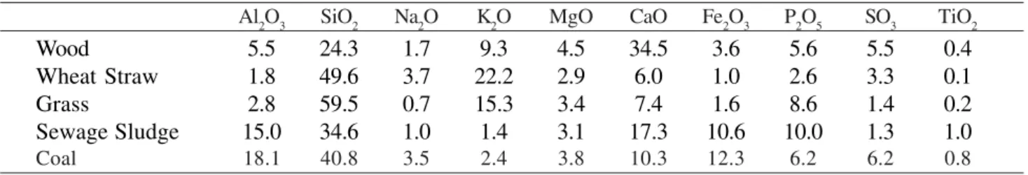
Table 1 illustrates the major differences between biomass fuels and coal. In general terms, they have higher moisture, lower ash (except sewage sludge), lower S and similar or higher Cl. Table 2 presents average ash composi-tions derived using standard ash analysis techniques de-rived to give comparable data for combustion systems. Noting the differences in ash contents from Table 1, it is also generally true that biomass fuels contain higher levels of alkali metals, in particular K. While, it must be noted that the artificial method used to generate ash for analysis was designed for coal combustion, the general findings listed do suggest that fouling and corrosion problems should be expected in biomass systems. Overall, there is a ten-dency for the higher Cl/lower S levels to favour the forma-tion of chlorides over sulphates while the lower ash con-tents provide less dilution of any deposits formed on plant components.
It is thought that the high K content combined with Cl is also responsible for the formation of low melting tem-perature compounds during combustion; the low S content
in many biomass fuels is another contributing factor. These low melting point ash constituents have led to the wide-spread fouling and severe corrosion problems experienced. In gasification systems, the situation is somewhat dif-ferent. There are several possible routes for minor and trace elements, such as Na or K, to take within a gasification system and through into the gas turbine. These routes vary from no response to the gasification process (and so exit with the ash/char/slag) through to the formation of vapour species that can pass through the whole hot gas path (and so be emitted from the process). In between these two ex-tremes, it is possible for reactions to take place forming (a) condensed particles and (b) vapour species that can con-dense onto entrained particles or plant components (de-pending on their specific operating conditions) along the hot gas path. The fate of the various trace elements is ele-ment-specific and in addition can be influenced by both the relative and absolute levels of other elements present in the fuels (e.g. S and Cl) and in any sorbents or catalysts used, as well as the composition of materials used for hot gas path components.
In order to determine the potential fate of trace elements within gasification systems using biomass fuels, one ap-proach is to investigate the thermodynamic equilibrium at various process stages. The thermodynamic analysis pack-age, MTDATA, has been used to predict trace element be-haviour followed by comparison of the trends identified with reported plant data and known operating experience. One of the aims of this work was to enable studies to be more closely focused on realistic deposit compositions when carrying out corrosion testing on materials intended for use within gasifier and gas turbine hot gas paths.
The thermodynamic study was carried out to determine which trace elements were more/less likely to enter the hot gas paths of gasification systems, condense onto system components and/or pass through into the gas turbine. This study investigated the stability of potential product com-pounds in gasifier fuel gases and their sensitivity to a number of important process variables:
• two example gasifier processes: an oxygen blown en-trained flow process and an air blown fluidised bed process2,6
Table 1. Average analyses of biomass and fossil fuels.
Wood Wheat ‘Grass’ Sewage Coal
Straw Sludge
Moisture (wt%) 20.7 10.7 14.9 19.5 8.2
Ash (wt%) 1.7 5.9 5.2 43.4 12.7
S (wt%) 0.2 0.1 0.2 1.0 1.7
Cl (wt%) 0.1 0.8 0.2 0.1 0.2
LHV, MJ/kg 18.6 17.3 18.3 10.7 26.2
Table 2. Ash analyses of biomass and fossil fuels.
Al2O3 SiO2 Na2O K2O MgO CaO Fe2O3 P2O5 SO3 TiO2
Wood 5.5 24.3 1.7 9.3 4.5 34.5 3.6 5.6 5.5 0.4
Wheat Straw 1.8 49.6 3.7 22.2 2.9 6.0 1.0 2.6 3.3 0.1
Grass 2.8 59.5 0.7 15.3 3.4 7.4 1.6 8.6 1.4 0.2
Sewage Sludge 15.0 34.6 1.0 1.4 3.1 17.3 10.6 10.0 1.3 1.0
• atmospheric and pressurised operation
• temperature ranges covering gasification and hot gas cleaning processes, as well as component operating temperatures
• a range of S and Cl levels to cover the potential ranges of fuels in coal and coal/biomass fired systems • the elements As, B, Ba, Be, Ca, Cd, Co, Cu, Hg, K, Mn,
Mo, Na, Pb, Sb, Se, Sn, V, Zn (Cr, Ni and Fe were not investigated as they are major alloying elements in materials used in components throughout the fuel gas paths).
Published literature surveys7-10 were critically evaluated
and care taken to avoid the pitfalls identified. For a power plant, it is important to note that kinetic effects may arise due to short gas residence times and/or slow reaction rates that could limit movement towards thermodynamic equi-librium. These effects apply especially to the bulk gases and will be less significant in the slower moving boundary layers adjacent to components.
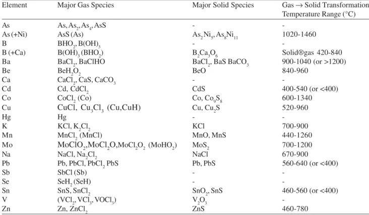
The results of this thermodynamic study are reported elsewhere11. Table 3 lists the major gaseous and condensed
phases and the temperature ranges for transitions between the gaseous and condensed states in gasification condi-tions. It should be noted that even elements with condensed phases can have significant vapour pressures. Table 4 groups
the elements in terms of their ‘volatility’, i.e. in order of the transitions from gaseous to condensed phases. This table does not correspond with the frequently quoted three-group classification of trace elements10. This classification was
originally developed for combustion systems and some re-ports directly translate this to gasification systems. As some-times noted before7,9 and found in this study, the same
clas-sification of elements is not applicable to combustion and gasification systems (and indeed there are several signifi-cant differences between types of gasification system).
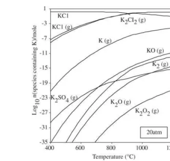
Figure 3 provides an example of the data generated during the thermochemical modelling; it shows the effect
Table 3. Summary of trace and alkali metal behaviour in gasifier gases.
Element Major Gas Species Major Solid Species Gas → Solid Transformation
Temperature Range (°C)
As As, As2, As4, AsS -
-As (+Ni) AsS (As) As2 Ni5, As8Ni11 1020-1460
B BHO2, B(OH)3 -
-B (+Ca) B(OH)3 (BHO2) B2Ca3O6 Solid®gas 420-840
Ba BaCl2, BaClHO BaCl2, BaS BaCO3 900-1040 (or >1200)
Be BeH2O2 BeO 840-960
Ca CaCl2, CaS, CaCO3 -
-Cd Cd, CdCl2 CdS 400-540 (or <400)
Co CoCl2 (Co) Co, Co9S8 600-1340
Cu CuCl, Cu3Cl3 (Cu,CuH) Cu, Cu2S 520-960
Hg Hg -
-K KCl, K2Cl2 KCl 700-900
Mn MnCl2 (MnCl) MnO, MnS 440-1260
Mo MoClO2,MoCl2O,MoCl2O2 (MoHO2) MoS2 700-1200
Na NaCl, Na2Cl2 NaCl 670-900
Pb Pb, PbCl, PbCl2 PbS Pb, PbS 560-640 (or <400)
Sb SbCl (Sb) -
-Se SeH2 (SeH) -
-Sn SnS, SnCl2 SnO2, SnS 460-560 (or <400)
V (VCl2, VCl3, VOCl3) V2O3
-Zn Zn, ZnCl2 ZnS 460-780
Table 4. Predicted volatility of trace and alkali metals in gasification gases.
Increasing Volatility Element
Hg, Sb, Se (As, V, B) Cd, Pb, Sn, Zn (As, B) Co, Cu, K, Mn, Mo, Na As, Ba, Be
Ca (V, As, B)
of increasing the pressure on the K equilibrium diagram for an air-generated fuel gas. The gas to solid transformation temperature of the major species, KCl, is increased from ~700 °C to ~900 °C when the pressure increases from 1 to 20 atm. Thus, subject to kinetic effects, increasing pressure can be expected to lead to condensation of KCl on higher temperature surfaces in the gasifier hot gas path, reducing the remaining levels of K vapour species in the fuel gas.
Other gas species can also influence condensation (dewpoint) temperatures. For example, increased levels of H2S can give, for different elements, higher or lower dewpoints (e.g. Zn or Sn) or different gas phase and/or con-densed species (e.g. Pb), so care is needed to ensure that the fuel gas compositions being modelled are complete and realistic.
To substantiate the effects identified by thermodynamic modelling, relevant process data were sought. There are some data for the removal of alkali, trace metals and chlo-rine species in gasification systems incorporating hot gas filters7,12-17. These data are not comprehensive and as each
gasification system has used different filtering temperatures, it is difficult to separate process differences from differ-ences arising from the use of different filter temperatures. However, it is reasonable to assume that reducing filter op-erating temperatures will reduce the passage of vapour phase contaminants through to the gas turbine, as it will drive the equilibrium towards condensed phases and reduce the va-pour pressure of the species remaining in the gas.
In many cases (e.g. for alkali metals, Zn, etc.), the
pre-ferred route of removal on economic grounds is by conden-sation/reaction with the fine particles present in the gas stream followed by particle removal by the hot gas filter. However, the coldest component in this hot gas path will be the heat exchanger that cools the gases prior to entry into the filter. The presence of ‘trace’ metals in heat ex-changer deposits at levels of several wt% has been frequently observed during component examinations and assessments (but only occasionally reported18,19). The large internal
sur-faces of the heat exchanger, ductwork and the filter unit itself provide potential sinks for condensed alkali/trace metals, especially if they are cooler than the gas stream. In a pressurised air blown fluidised bed gasifier pilot plant7,
deposits of the more volatile ‘trace’ metals at levels of sev-eral wt% were observed on the surfaces of pipes on the ‘clean’ side of the filter unit. In addition, a reduction in S and Cl-containing species has been noted across hot gas filter units, presumably as a result of reactions with the fil-ter cake formed on the dirty side of the filfil-ter units.
The information available for alkali and trace metal spe-cies all show that lowering the filter temperature reduces the amount of vapour phase species present in the remain-ing fuel gas stream (and enriches the filter fines in these elements) 7,20. Unfortunately, filter operating temperatures
cannot just be lowered to the levels needed to remove most of these vapour species, as the lower limits for filter opera-tion are dictated by other gasificaopera-tion processes parameters: e.g. tars and ammonia-derived compounds need to be kept in the vapour phase to avoid blinding of the filters. The
available data are most comprehensive for alkali species on which many studies have been targeted. This is despite the importance of other trace elements, e.g. Pb, which are present at similar, if not higher, levels in gasification fuel gas streams and are also important in determining gas tur-bine component lives7,14-16. In work carried out at VTT13,
the most significant levels of elements found in the fuel gas were for Cd, Pb and Zn. The levels of several trace metals (e.g. Pb) and alkalis (e.g. Na, K) reported in these studies are higher than those currently acceptable for gas turbines, and in some cases it is likely that the true values of vapour phases species in the gasifier product gases are higher still7.
From plant data, filter temperatures below 400°C may be required to reduce contaminants to acceptable levels for the gas turbine. In other cases, supplementary gas cleaning stages or the use of a scrubber may be required or the use of a scrubber to meet the required target, impacting signifi-cantly on costs and cycle efficiency. But the level accept-able to the turbine depends on the life required of gas tur-bine parts, the temperatures at which they work and the materials/coatings used, so there is potential scope for com-promise here also. This is discussed later in this paper.
The main points arising from the above analysis are summarised as follows: (i) fuel composition: on a mass com-parison basis, the critical contaminants species (S, Cl, alka-lis and trace metals) of many biomasses are similar or lower than coal – notable exceptions are K and Cl in straw; P, Cd, Pb and Zn in wood (as well as Ba, Cr, Cu, Mn); V and Zn in sewage sludge (as well as Cr, Cu, Mn, Hg); (ii) fuel gas compositions vary significantly between gasification sys-tems at the trace contaminant level (as well as the frequently reported bulk gas composition level); (iii) most trace and alkali metals are more volatile in gasification systems than in combustion systems – the same classification of volatil-ity as for combustion gases is not applicable (different spe-cies are volatile); (iv) Sand Cl levels (both absolute and relative), as well as operating pressure and gasification proc-ess can influence the volatility of trace and alkali metal species; (v) potentially damaging levels of Pb, Zn, Cd and Sn (and V in some systems) can all pass through the fuel gas path to the gas turbine, as well as alkali metals (Hg, B, Sb and Se can also pass through the gas turbine); and, (vi) the high levels of trace metals present in gasifier product gases can be reduced by use of low filter operating temperatures (e.g. 250 - 450 °C dependent on the gasification system).
3. Contaminant Effects on Gas Turbine
Components
In all biomass combined cycle systems the performance of the gas turbine is vital to the overall plant efficiency and economic viability. However, within these systems hot cor-rosion and/or ecor-rosion are likely to be life limiting for the
gas turbine vanes and blades, rather than the creep and fatigue processes that limit their lives in the longer term due to the expected contaminant levels.
The environments found within the hot gas paths of gas turbines depend on the contaminants present in the fuel and air entering the turbine, as well as the turbine operating conditions. Industrial gas turbines have been developed to fire on a wide variety of fuels, ranging from natural gas to sour gases and heavy fuel oils. The degradation of materi-als in such systems has been the subject of many investiga-tions during the past 40 years, as operating condiinvestiga-tions have developed and/or fuels have changed, and the potential problems which many be encountered in gas and oil fired gas turbines have been well characterised21,22.
Many similar types of materials degradation can be ex-pected in gas turbines using solid fuel derived fuel gases, as some of the contaminant species are the same as for oil and/or gas fired systems. However, the contaminant levels are different, there are additional as well as absent species and the sources/forms of the contaminant species also dif-fer. Fuel gases derived from biomass have the potential to cause both erosion and corrosion damage to gas turbine hot gas path components. Fuel derived particles can cause either erosion damage or deposition depending on the par-ticles’ size and composition, as well as aerofoil design and operating conditions. Corrosion can result from the com-bined effects of gaseous species (e.g. SOx and HCl) and deposits formed by condensation from the vapour phase (e.g. alkalis and other trace metal species) and/or particle impaction and sticking.
The mode of corrosion damage is highly dependent on the local component environment. Conventionally, the metal vapour species of most concern were alkalis (mainly Na) and S in gas turbines fired on clean fuels (either as fuel contaminants or via the combustion air) or V from heavy fuel oils. In biomass fired systems the levels of both SOX and HCl can be similar to (or higher for HCL) than those from a coal gasifier (see Table 1). Also, the fuel gas may contain significant levels of alkali metals (in particular K) and heavy metals, e.g. Pb and Zn23, depending on the type
of biomass (Table 2) and the effectiveness of the gas clean-ing approach. If a water or chemical scrubber is included (as in the ARBRE scheme for ammonia removal), the levels of these contaminants will be significantly reduced whereas a hot dry cleaning approach will potentially lead to higher levels, depending on the operating temperature of the fil-ter.
revised25-26, to take into account the significant differences
with these new fuel compositions, as well as the damage rates that will be acceptable for these new power systems.
In order to identify whether the residual levels of con-taminants (such as K) in a ‘cleaned’, biomass-derived fuel gas will restrict the operating life of gas turbine compo-nents, it is necessary to understand their deposition behav-iour and the effects the resultant deposit may have on the blade and vane materials and coatings.
Thermodynamic analysis methods were also applied to the gas turbine, using the results of the gasifier fuel gas study to identify the elements that can pass through into the gas turbine, as well as realistic ranges for the different contaminant levels. Figure 4 illustrates the results obtained for K dewpoint temperatures, which are plotted as a func-tion of contaminant levels for different SOX and HCl levels and gas pressures. In a gas turbine combustion gas, K2SO4 is the equilibrium K compound in deposits rather than KCl which will persist in the gas phase. Figure 4 shows that the K2SO4 dewpoint increases with increasing K or SOX levels in the gas stream, as well as gas pressure, but decreases with increasing HCl levels in the gas stream.
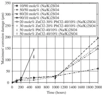
Once deposited, there are significant differences between the effects of the various deposits; described in detail else-where27,28. This is illustrated in Fig. 5 for a ‘deposition flux’
of 5 µg/cm2/h, in which ‘maximum’ corrosion damage
val-ues ( damage with a 4% probability of being exceeded) are plotted as a function of exposure time(data from laboratory
corrosion tests). The samples with this ‘deposition flux’ at 700 °C have a clear incubation period for all the various deposit compositions. However, this incubation period is significantly shorter for the Pb/Zn containing deposits, than the alkali sulphate deposits, though there are still signifi-cant differences in damage with varying Na/K ratios in these ‘deposits’ after 2000 h testing. Similar deposit composi-tion effects were observed at other deposicomposi-tion fluxes27.
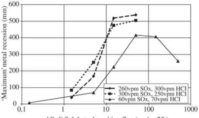
The effect of deposition flux on the maximum corro-sion damage obtained for IN738LC at 700 °C with a de-posit mix of 80/20 mole% (Na/K)2SO4 is illustrated in Fig. 6. This is typical of the response of gas turbine materials, with the dependence of corrosion rate on deposition flux being approximately sigmoidal with three distinct behaviour re-gimes30:
- at low deposition fluxes (< ~1 µg/cm2/h) there were
low corrosion rates;
- at intermediate deposition fluxes (from ~1 to ~30 µg/cm2/h), much higher corrosion rates were
found with a dependence on deposition flux close to linear;
- at high deposition fluxes (> ~30 µg/cm2/h), a thick
scale/deposit layer was found which stabilises or even slightly reduces the corrosion rate with further in-creases in flux.
The effect of varying SOX and HCl concentrations on the hot corrosion damage of IN738LC at 650 and 700 °C were evaluated from a series of tests in which each of these
Figure 4. Dependence of K2SO4 dewpoint on gas pressure, S, Cl and K levels
Figure 5. Effect of different deposit compositions on ‘maximum’
corrosion damage to IN738LC at 700°C (deposition
flux = 5 µg/cm2/h, SO
contaminants such as KCl. But as the gas is cooled substan-tially prior to scrubbing to minimise energy losses and to meet scrubber entry requirements, many of the trace con-taminants may well have condensed onto entrained particulates or component surfaces, before the gas reaches the scrubber. To minimise costs, these systems do not have filters prior to the scrubber as for most large coal-fired IGCC plants, so the dissolved contaminants and the particulates will end up in the scrubber discharge. From the gas turbine perspective, the scrubbed fuel gas should not present any problems as nearly all fuel-borne contaminants should have been removed.
For the higher efficiency, pressurised systems appropri-ate hot, dry gas cleaning schemes are required to avoid the higher costs of scrubbing the high pressure fuel gas. Filtra-tion is the key element, allowing the combinaFiltra-tion of particulate removal with condensed trace contaminants dependent on the filtration temperature. Filtration also al-lows for the use of in-duct injection of sorbents to reduce alkalis and HCl with minimal extra complication. How-ever, because of the need to retain any uncracked residual tars in the vapour phase and the need to avoid condensa-tion of ammonium compounds (both of which would lead to blinding of the filter elements), filtration temperatures cannot be reduced excessively in the drive to limit trace species. In these schemes, costly additional catalytic NOx reduction measures either upstream or downstream of the gas turbine may be needed. The gas turbine in these sys-tems will be passing reduced levels of fuel-borne contami-nants which pass the gas cleaning stages. There is scope to adjust the operation and materials of the turbine to suit the biomass fuel used; while, use of the highest efficiency tur-bine is an attractive option, it may prove uneconomic when the required gas cleaning costs are considered.
References
1. Energy for the Future: Renewable Sources of Energy – Campaign for Take-off - a Community Strategy and Ac-tion Plan, EU Commission Paper, 1998.
1. Bridgwater, A.V. Biomass Gasification for Power Genera-tion’, Fuel, v. 74, n. 5, p. 631-653, 1995.
2. Rensfelt, E. Gasification Technology for Biomass and Other Solid Fuels, Biosolids Energy Recovery Technol-ogy Seminar, IWEX 2001, Birmingham UK, 2001. 3. Stahl, K.; Neergaard, M. IGCC Power Plant for Biomass
Utilisation, Varnamo, Sweden, Biomass and Bioenergy, v. 15, n. 3, 1998.
4. ‘Gas turbines in advanced co-fired energy systems’, ECSC Project 7220-PR/053
5. Takematsu, T.; Maude, C.W. Coal Gasification for IGCC Power Generation, IEACR/37, IEA Coal Research, Lon-don, UK (1991).
Figure 6. Effect of alkali sulphate flux and gaseous reactants on ‘maximum’ metal damage recession of IN738LC at 700 °C29.
contaminants was varied for the same ‘deposit’ composi-tion (80/20 mole % (Na/K)2SO4 ) and a series of ‘deposition fluxes’. It was found that the effect of SOX levels was much more significant than HCl27,30.
From the above, it is clear that great care is required in the control of trace alkali and other contaminants because of their potential to cause excessive corrosion damage to the hot gas path components of a gas turbine or gas engine using a biomass-derived fuel gas. The exact level of dam-age that can be tolerated depends on specific process and operating parameters (e.g. temperatures, materials, repair/ replacement strategy etc.), as well as economic factors. It may be possible to optimise the materials selection and operating conditions of a gas turbine, in combination with a comprehensive maintenance strategy (to allow it to han-dle higher than currently specified contaminant levels) in-stead of bearing the high cost of an elaborate gas cleaning system.
4. Conclusions for biomass combined cycle
systems
From the above, it is clear that care is needed in design-ing the process flowsheets for biomass systems. In particu-lar, those for fuels such as wheat straw, with very high K and Cl levels, require careful consideration of the removal of fuel contaminants so that a reliable and cost effective gas cleaning approach can be adopted.
6. Reed, G.P. Control of Trace Elements in Gasification, Ph.D. Thesis, Imperial College, London (2000). 7. Frandsen, F.; Dam-Johansen, K.; Rasmassen, P. Trace
El-ements from Combustion and Gasification of Coal – an Equilibrium Approach, Prog. Energy Combustion Sci., v. 20, p. 115-138, 1994.
8. Fantom, I.R. An Assessment of Trace Element Concentra-tions in the British Coal Topping Cycle, Power Genera-tion Report, n. 121, CRE, British Coal, 1991.
9. Clarke, L.B.; Sloss, L.L. Trace elements – emissions from coal combustion and gasification, IEACR/49, IEA Coal Research, London, 1992.
10. Kilgallon, P.J.; Simms, N.J.; Oakey, J.E. Fate of Trace Contaminants from Biomass Fuels in Gasification Sys-tems, to be published in Materials for Power Engineer-ing, Liege, 2002.
11. 4th International Conference on Gas Cleaning at High
Temperatures, Karlsruhe, Germany (Sept. 1999). 12. Nieminen, M. et al., Raskasmetallien käyttäytyminen
turpeen ja kivihiilen leijukerros- kaasutuksessa, LIEKKI-Combustion Research Program. Project Report, 1991. 13. Kurkela, E. et al. Pressurized fluidized-bed gasification experiments with biomass, peat and coal at VTT in 1991-1994. Part 3. Gasification of Danish wheat straw and coal, VTT Publication, v. 291, 1996.
14. Kurkela, E. et al. Pressurized fluidized-bed gasification experiments with wood, peat and coal at VTT in 1991-1992. Part 1. Test facilities and gasification experiments with sawdust, VTT Publication, v. 161, 1993.
15. E. Kurkela et al., ‘Pressurized fluidized-bed gasifica-tion experiments with wood, peat and coal at VTT in 1991-1994. Part 2. Experiences from peat and coal gasi-fication and hot gas filtration’. VTT Publication 249, (1995).
16. ‘Integrated hot fuel gas cleaning for advanced gasifica-tion combined cycle processes’. LIEKKI- Combusgasifica-tion and Gasification Research Programme. LIEKKI-vuosikirjat, projekti: 410 (1996).
17. Proc. Corrosion in Advanced Power Plants, Special Is-sue of Materials at High Temperatures, vol.14 (1997). 18. Proc. First International Workshop on Materials for Coal
Gasification Power Plant, Special Issue of Materials at High Temperature, vol. 11 (1993).
19. Mitchell, S.C. Hot gas clean-up of sulphur, nitrogen, minor and trace elements, IEA Coal Research, UK, 1998. 20. Sims, C.T.; Stoloff, N.S.; Hagel, W.C. Superalloys II,
Wiley (1987).
21. ‘Hot Corrosion Standards, Test Procedures and Perform-ance’, High Temperature Technology vol. 7 (4) (1989). 22. ‘Co-gasification of Coal/Biomass and Coal/Waste Mix-tures’, Final Report EC APAS Contract COAL-CT92-0001, University of Stuttgart, Germany (1995). 23. ASTM D2880, Standard Specification for Gas Turbine
Fuel Oils (1990).
24. Decorso, M.; Anson, D.; Newby, R.; Wenglarz, R.; Wright, I.G. Int. Gas Turbine and Aeroengine Congress, Birmingham, UK, ASME Paper 96-GT-76, 1996. 25. Wright, I.G.; Leyens, C.; Pint, B.A. in Proc. ASME
TURBOEXPO 2000, Munich, Germany, ASME Paper 2000-GT-0019, 2000.
26. Simms, N.J.; Encinas-Oropesa, A.; Kilgallon, P.J.; Oakey, J.E. Performance of Gas Turbine Materials in ‘Dirty Fuel’ Environments, to be published in Materials for Power Engineering, Liege, (Oct.2002).
27. Leyens, C.; Wright, I.G.; Pint, B.A. Hot Corrosion of Nickel-based Alloys by Alkali-containing Sulfate De-posits, 5th International Symposium on High Tempera-ture Corrosion and Protection of Materials, Les Embiez, France (May 2000).
28. Simms, N.J.; Smith, P.J.; Encinas-Oropesa, A.; Ryder, S.; Nicholls, J.R.; Oakey, J.E. in Lifetime Modelling of High Temperature Corrosion Processes, Eds M. Schütze et
al, EFC No. 34 (Maney Publishing, London), p.
246-260, 2001.