311
Abstract
Tumbling mills are often taken as the object of optimization studies because they are a type of equipment that consume large amounts of energy. Among the cur-rent available resources to conduct such studies, mathematic modelling presents great eficiency due to its low cost, speed and reliability.
The total charge and grinding media charge are very important variables to conduct modelling exercises that aim at power draw and product size distribution forecasting. However, the common measurement methods require people entering the equipment, which carries a number of adversities related to conined spaces.
In this regard, this paper presents the development of a method and the prototype of a device able to measure tumbling mill charges, quickly, precisely, with low cost and, above all, ensuring safety.
The result of this work is a method that allows equivalent or superior precision in comparison to the existing methods, whose main aspect is to eliminate the require-ment of people entering dangerous environrequire-ments, such as tumbling mills.
Keywords: mills, safety, grinding, charge.
Resumo
Moinhos de bolas são, frequentemente, objeto de estudos de otimização, pois são equipamentos que consomem muita energia. Tais estudos são conduzidos sis-tematicamente sob enfoque de modelagem matemática, pois tal recurso é rápido, eiciente, de alta coniabilidade e de baixo custo.
A carga total e carga de corpos moedores são variáveis muito importantes para exercícios de simulação, que visam a estabelecer previsões de potência de operação e distribuições granulométricas. Entretanto medições de graus de enchimeto requerem medições por pessoas na câmara de moagem, sob condições de risco elevado associa-dos a espaços combinaassocia-dos.
Nesse aspecto, o presente trabalho mostra o desenvolvimento de um método e um protótipo de um dispositivo para medição de cargas em moinhos tubulares, de forma precisa, rápida e com baixo custo e, acima de tudo, que minimiza riscos. O resultado é um método com precisão igual ou maior do que dispositivos semelhantes, cujo principal aspecto é apenas o de eliminar o risco associado a pessoasl entrarem em câmaras internas de moinhos tubulraes.
Palavras-chave:moinhos, moagem, carga.
Eduardo Nozawa Caetano de Araujo
Mining and Mineral Processing Engineer Metso Brazil
Iporanga – Sorocaba – SP [email protected]
Prof. PhD. Homero Delboni Jr.
Mining and Petroleum Engineering Department University of Sao Paulo Brazil
Butantã – Cidade Universitária – São Paulo [email protected]
Development of a Method
to Measure Charges
in Tumbling Mills
Desenvolvimneto de método para medição
de cargas em moinhos tubulares
Mining
Mineração
1. Introduction
sam-312
2. Common Methods to Measure Tumbling Mills Charges
The charge level of a mill can be described as the volume occupied by the grinding media (including empty spaces) as a fraction of the total volume avail-able inside the equipment. Assuming this deinition, other measurements may be taken considering the total charge
that includes the rock charge; in this case, applicable to SAG and AG mills.
The charge level is the variable that most contributes to the power draw. It is completely relevant to know the charge level in sampling campaigns, and during operation, in order to succesfuly
conduct mathematical modelling and simulations.
The common technique to mea-sure the charge level of tumbling mills requires at least two people measuring the charge width (S), as exempliied on the Figure 1.
Figure 1
Charge Geometry description
Under a practical point of view, usually three or four measurements of S are taken. On the other hand, there is an
indirect procedure to obtain other two measurements considering the diagonal of the rectangular surface that describes the
charge level. In this case, S is calculated considering the belly length. Figure 2 ilustrates these diagonals.
Figure 2
Diagonals of the charge surface
Allis Chalmers (apud Napier Munn et al., 1996) proposed the
fol-lowing formula that considers the height between liners on the top position and
the charge surface.
Where:
H = height from top liners and the
charge surface level (m)
D = mill diameter(m), inside liners
Morrell (1994) demonstrated that Equation 1 presents errors when measuring charge levels below 20%, a common situation in SAG mills. In addiction to that, many times there are
practical limitations for measuring the heights of large diameter mills.
Another way, almost not docu-mented, but very oftern praticed, is the counting of exposed liners in order to
ind the equivalent α angle, also ilus-trated in Figure 1. The error, in this case, depends on the interpretation of the fraction of exposed liners that are in contact with the charge.
pling campaigns, which is an essential step in milling circuit optimization studies.
Entering a mill requires the accom-plishment of a number of requirements that several times consumes costly time
for the mining companies due to plant interruptions. These requirements cannot be dismissed as they are closely associated to safety and health, themes that must be taken as priority in an industry historically
known for its hazard environment. Thus, a form of eliminating, or at least reducing some risks, would be for the people to avoid entering the equipment by using a device placed outside the conined space.
MCP Method
Some premises were considered for alternatives to the common methods. However the mathematical treatment of a cloud of points describing the mill’s internal surface presented the most
suit-able solution for the pestablished re-quirements. The main aspects considered were: to avoid people entering the mills and costs.
A prototype was built and named
MCP or Mill Charge Proiler. The instru-ment was designed to measure the position of a number of points within the limits of a conined space, describing these points by spherical coordinates and a laser distance
313
Figure 3 Mill Charge Profiler
After preliminary tests, the device demonstrated successfully that it was able to generate the desired cloud of points. In order to interpret the cloud data, a math-ematical treatment that followed through a number of steps considering vectorial corrections, orthogonal projections, curve
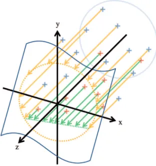
itting and error estimates was developed. In spite of being a 3D problem, the interpretation was built in 2D through the projection of all captured data points onto a plane perpendicular to the mill center line. Figure 4 illustrates the projection of the cloud on the mentioned plane. The
points corresponding to the liners (blue crosses) were projected (orange arrows) to it a circumference (orange dashed circun-ference) and the points corresponding the charge (red crosses) were projected (green arrows) to fit by a polynomial (green dashed line).
Figure 4 Projection of the cloud onto the plane XY
Time could be saved during the placement of the device because it was not necessary to apply any bubble level-ing procedure. The mathematical data treatment was able to determine the posi-tion of the plane, the coordinates of the circumference center and its radius and inally the coeficients that describes the
polynomial that its to the points associ-ates to the charge.
Once found the mathematical de-scriptions of the circumference and the polynomial, the area ocupied by the charge is then calculated.
Later, the fit error is estimated through the deviation of the
circumfer-ence radius with estatistical distribution and conidence interval. Invariably, the average distance among the projected points and the circumference is zero, but the individual distances deviation can be estimated through t-student distribuition due to the limited amount of points, usu-ally fewer than 30
3. Results
Three equipment surfaces were measured. The first equipment was a flotation column not yet installed and stored on the horizontal position. Regardless of not being a mill itself, the internal surface was very similar to the proposed problem and the cell
was considered the base case of the test campaign due to its dimensional conidence. The second equipment was measured during a maintenance stop. It was a ball mill installed in a bauxite processing plant. The third equipment was a SAG mill with 32’ (9.75 m)
di-ameter, installed in a gold and copper plant. The measurements in the SAG mill were conducted after a grind out. Figure 5 illustrates photographs of the equipment and the Figure 6 demon-strates an example of projected points, itted circumference and polynomial. meter. The base of the device was inspired
from an Alt-Azimutal mechanism. Some modiications were adapted in order to allow a wider angular range, suitable
to measure mill’s internal from its feed trunion. The laser distance meter chosen was a Bosch DLE 50, able the measure up to 50 m with precision of 1.5 mm.
314
Figure 5
Measured equipment
Figure 6
Projected points, fit circu-mference and polynomial
For each type of equipment, the charge level was also calculated through
other possible common methods. Table 1 summarizes the results.
Measurement Method Diameter (m) Charge Level (%) charge level Minimum (%)
Maximum charge level (%)
Radius error, CI 98%
Flotation Cell
Height 2.418 38.5 - -
Allis Chalmers 2.418* 38.4 - -
MCP 2.418 38.5 - - 0.25
Ball Mill
S width 3.22* 30.7 27.9 34.2
Height 3.22* 26.0 25.6 26.4
Allis Chalmers 3.22* 25.6 25.2 26.0
Exposed liners counting 3.22* 28.2 24.3 32.3
MCP 3.216 27.0 - - 0.43
SAG Mill
Mill design 9.52 - - -
S width 9.54* 17.9 17.6 18.2
Height 9.54* 18.5 18.4 18.6
Allis Chalmers 9.54* 17.3 17.2 17.3
Exposed liners counting 9.54* 17.5 16.2 18.8
MCP 9.535 18.6 - - 0.37
Table 1
Results Summary
315
4. Discussions
The accuracy estimated for the lo-tation column diameter was considered to be excellent, taking into account that the MCP was designed with an angular precision of 0.5 degrees and distance precision of 1.5 mm. An error of 3.0 mm on the radius within the conidence in-terval of 98% achieved the expectations for this case, and was considered ideal. The calculated relative error was 0.25%. In the ball mill, the estimated error for the radius was calculated as 7.3 mm. Considering that the liners were worn and that it was not possible to ensure that the laser was pointed precisely at the bottom region of the liner waves, this error can be considered very acceptable and consistent with the base case. In this equipment, the relative error was 0.43%. In the SAG mill, the estimated error was 18 mm and the calculated diameter was 9.535 m. Consulting design drawings, the diameter inside liners would be 9.52 m, thus the value calculated with the MCP was very consistent, even consid-ering the liners wear. The relative error for the SAG mill was 0.37%. Among all the studied cases, all the errors pre-sented consistent values, with the same magnitude.
In the lotation column, four direct measurements were taken of its diam-eter, resulting in a very accurate average of 2.418 m. The diameter calculated through the MCP was identical. The “charge” was calculated to be 38.5% with the MCP and through the direct measurement of the “charge” height (true value). Applying the diameter and the height to the Allis Chalmers formula, the result obtained was 38.4%, indicat-ing that the formula was valid for this test that presented a high “charge” level.
In the ball mill, measurement by MCP resulted in a charge level of 27.0%.
The measurements conducted with S width presented a wide variability, with an average of 30.7% that could be between 27.9 and 34.2 with 90% conidence. Considering the heights, the obtained results were 25.6 and 26.4%, and applying the Allis Chalmers formula, the results were 25.2 and 26.0%. Count-ing the exposed liners, the charge value was estimated to be 28.2%
The value of 30.7% obtained through the S width method was super-estimated in comparison to the other methods. The methods that take the height as the main input presented results below 26.5%, but it should be taken into account that the central portion of the charge had a lower level in comparison to the edges in contact with cilinder liners. This observation also explains the higher charge (28.2%) estimated using the method of counting the exposed liners.
The measurement through the S width method presented differences of up to 5 cm, which is very acceptable, considering the charge shape irregularity, the dificulty in establishing a criterion deining the beginning and the end of the measurement, and also the dificulty in keeping a regular stretching on the measurement tape.
When converting the diagonal measurements into the equivalent S width, increased differences between the equivalent S width were observed. The original measurements of the diagonal were 7.10 and 7.14 m and the equivalent S width for these diagonals were 3.03 and 3.12 m. Thus, the difference increased from 4 to 9 cm. The equivalent S width of diagonal resulted in completely distinct charge levels of 29.2 and 35.1%.
In the SAG mill, in addition to the dificulties previously mentioned, the typical pushing environment of the
industrial plants was experienced, due to production demands. Before the ap-plication of the MCP, a survey campaign involving the collection of a number of samples in several points of the plant was conducted with PI data instruments and at the end a crash-stop was followed by a grind out of the SAG mill.
The measurements with the MCP resulted in a charge level of 18.6%. The measurements taken through the S width presented low variability. On the other hand these values were sistematically lower. The average charge level calcu-lated through the S width method was 17.9% that could be between 17.6 and 18.2% within a conidence interval of 90%.
For the calculations solely consid-ering the heights, the obtained results were 18.4 and 18.6%, which were very close to the MCP results and also took into account that the charge presented a lat shape. Applying the Allis Chalmers formula, the obtained value was 17.3%, which is out of the valid range (the formula is valid for charge levels above 20%). Through the counting of exposed liners, the charge level was estimated to be between 16.2 and 18.8%
The S widths presented differences of up to 3 cm on the direct measurements and also on the diagonals, which is very acceptable considering all the irregulari-ties and the internal size of the SAG.
A small increased difference be-tween the equivalent S width calculated from the diagonals measurements was noted. The original measurements were 12.44 m and 12.46 m and the equivalent S width for these diagonals were 8.03 and 8.06 m. These differences did not re-sult in contradictory charge level such as observed in the ball mills. The obtained values were 17.4 and 17.6%.
5. Conclusions
The MCP demonstrated to be a fea-sible, precise and safe alternative to measure the charge of tumbling mills. The MCP avoids the entrance of people into the mills which are conined spaces, frequently char-acterized by inhospitable conditions such as high temperatures and humidity, risks of falling, slipping, explosion and falling balls, presence of toxic gases, among others.
The mathematical treatment demon-strated to be eficient, fast and did not
de-mand the application of any CAD software for the interpretation of results. It did not require the use of equipment bubble leveling or the taking of an origin point. With this concept, about 10 minutes could be saved during the measurements.
A device with a more precise angu-lar resolution could contribute to a more accurate result. In addition, the way of interpreting the calculated errors, it should be taken into account that the liner surfaces
have irregularities that cannot be precisely evaluated while pointing the laser. More-over, there are variations due to liner wear.
Thus, the measurement errors should predictably achieve the magnitude of a few milimeters.
ex-316
6. References
AL-SHARADQAH, A. CHERNOV, N. Error analysis for circle itting algorithms,Electronic Journal of Statistics, 886-911, 2009.
BERALDO, J.L. Moagem de minérios em moinhos tubulares. São Paulo: Editora Edgard Blücher, 1987.
BOND, F.C. Crushing and grinding calculations.Allis Chalmers Publication, n. 07R9235B, 1961
CHAVES, A.P. Teoria e prática de tratamento de minérios, britagem, peneiramento e moagem.
São Paulo: Signus Editora, 1999. v. III.
CHERNOV, N. LESORT, C., Least squares itting of circles. Journal of Mathematical Imaging and Vision, 239-251, 2005.
HUMES, A.F.P. de C. et al. Noções de Cálculo Numérico. São Paulo: McGraw-Hill do Brasil, 1984, p.93-109, 158-174.
LASDON, L.S., WAREN, A.D., Generalized reduced gradient software for linearly and non-linearly constrained problems. in: Greenberg, H.J., (Ed.) Design and implementation of optimization software. Sijthoff and Noordhoff, Holanda, 1978, p.335-362.
MOON P, SPENCER DE. Spherical coordinates (r, θ, ψ). Field theory handbook, including coordinate systems, differential equations, and their solutions. New York: Springer-Verlag. pp. 24–27, 1988. p. 24-27. (2nd and 3rd print corrected)
MORRELL S. Power draw of grinding mills – Its measurement and prediction. 5th Mill Ops
Conf, Roxby Downs, Oct, 109-114 (AusIMM), 1994.
MORRELL S. Power draw of wet tumbling mills and its relationship to charge dynamics. Trans Inst Min Metall, 105, Jan-Apr, 1996.
NAPIER MUNN, T.J., MORRELL, S., MORRISON, R.D., KOJOVIC, T. Mineral commi-nution circuits – their operation and optimisation. Brisbane – AU:Napier Munn, T.J. Ed., JKMRC, 1996.
NR-33 Segurança e Saúde nos Trabalhos em Espaços Coninados, Publicação D.O.U, Portaria SIT n.o 202 22/DEZ/2006.
ROWLAND Jr, C.A. Selection of rod mills, ball mills, pebble mills and regrind mills. Design and installation of comminution circuits (Eds: Mular and Jergernsen), SNE/AIME, New tork, p.393-438, 1982.( Eds.: MULAR and JERGERNSEN)
ROWLAND Jr, C.A., KJOS, D.M. Rod and ball mills. Ch12 in Mineral Processing Plant, SME, 1978. 883p. (Eds.: MULAR and JERGERSEN).
ROBINSON S.M., Fitting spheres by the method of least squares Commun. Assoc. Comput. Mach. 4, 491, 1961.
TAGGART, A.F. Handbook of mineral dressing. New York: Wiley, , 1945.
TAUBIN, G. Estimation of planar curves, surfaces and nonplanarspace curves deined by im-plicit equations, with applications to edge and range image segmentation.IEEE Trans. Pat-tern Analysis Machine Intelligence 13 1115–1138, 1991.
pected to be on the scale of centimeters. The precision of the laser is on the milimeters scale, so it does not make sense to estimate an error for the charge surface.
On the S width method, small direct
measurement differences cause big varia-tions on the charge level estimatives and the trend of such errors is to increase in smaller diameter mills, which is the case of the measured ball mill.
The MCP eliminates vague criterias adopted by people while measuring mill in-ternally by common methods. Among these criteria, the physical limits of the charge and the measuring tape stretch.