Departamento de Electrónica, Telecomunicações e Informática
André
Amaral Costa
AVALIAÇÃO DE UM SISTEMA WIMAX
PARA APLICAÇÕES VEÍCULO-INFRAESTRUTURA
Universidade de Aveiro 2008
Universidade de Aveiro 2008
Departamento de Electrónica, Telecomunicações e Informática
Dissertation presented to the University of Aveiro to fulfill the necessary requirements for obtaining a Master Degree in Electronic and Telecommunications Engineering, written with the scientific orientation of Prof. Paulo Pedreiras, Professor at the Electronic, Telecommunications and Informatics Department at University of Aveiro.
André
Amaral Costa
ASSESSING WIMAX FOR VEHICULAR COMMUNICATIONS
APPLICATIONS
AVALIAÇÃO DE UM SISTEMA WIMAX PARA APLICAÇÕES
VEÍCULO-INFRAESTRUTURA
Júri
Presidente
Dr. António Manuel de Brito Ferrari AlmeidaProfessor Catedrático da Universidade de Aveiro
Vogais
Dr. José Alberto Gouveia Fonseca (Co - Orientador)Professor Associado da Universidade de Aveiro
Dr. Francisco Manuel Madureira e Castro Vasques de Carvalho
Professor Associado do Departamento de Engenharia Mecânica e Gestão Industrial da Faculdade de Engenharia da Universidade do Porto
Prof. Dr. Paulo Bacelar Reis Pedreiras (Orientador)
Acknowledgements
First of all, I would like to express my gratitude to my supervisor and co-supervisor, Prof. Paulo Pedreiras and Prof. José Alberto Fonseca, for their guidance and help during this past year that made possible to perform my study.I would also like to thank my project colleague, Hugo, because without the work that we performed together and help that we gave to each other, this study wouldn't be possible to achieve.
I would also like to show my gratitude to Eng. Álvaro Gomes from PT Inovação because he was always ready to help. Thank you also to my other project colleague, Miguel Pereira, that was always supportive. I would like to thank to the person who helped me the most during this past year. So, I would like to thank my girlfriend, Filipa, for being there, helping me in this past three years and a half always being supportive and always giving me all the affection that I needed.
A special thank to my friends and family for all the moments of support that they give me.
For last, I would like to thank to the Electronic, Telecommunications and Informatics Department of University of Aveiro and to the Institute of Telecommunications at Aveiro.
Palavras-Chave
Segurança, Auxílio Inteligente ao Condutor, Comunicações sem Fios, WiMAXResumo
Os acidentes rodoviários têm um enorme impacto na sociedade, quer devido às perdas humanas daí resultantes quer devido aos custos económicos a si associados. Por todo o mundo, esta situação levou ao estudo de mecanismos que permitem aumentar a segurança nas estradas. Por exemplo, na Europa estão a ser financiados vários projectos para desenvolver estes mecanismos e a maior parte das iniciativas em curso requerem a possibilidade dos veículos comunicarem entre si e/ou com estações que se encontram fixas junto à estrada. Devido aos requisitos de mobilidade dos veículos, as tecnologias de comunicação sem fios têm um papel crucial neste tipo de aplicações. Neste sentido, esta dissertação avalia a adequação da tecnologia de comunicação sem fios WiMAX para a transmissão de serviços de segurança rodoviária e/ou outros, entre os veículos e a infraestrutura, usando para isso os mecanismos integrados de diferenciação de tráfego desta mesma tecnologia de comunicação. Especificamente, o objectivo é avaliar se estes mecanismos são apropriados para fornecer os serviços atrás mencionados tendo em conta os seus requisitos tempo-real (largura de banda, latência, variação da latência, etc.).Keywords
Safety, Intelligent Driver Aids, Wireless Communications, WiMAXAbstract
Road accidents have a huge impact on the society, both because of the resulting human life losses and injuries as well as because of the associated economic costs. This situation fostered the study of mechanisms for increasing road safety all over the world. In Europe, several projects are being funded to develop such mechanisms. Many of the approaches that are being pursued require the ability of the vehicles to communicate with each other and/or with fixed roadside equipments. Due to the mobility constraints, wireless technologies have a crucial role in this kind of applications. This dissertation assesses the suitability of the WiMAX wireless technology for supplying vehicle to infrastructure road safety services and others, using this communication technology integrated quality of service mechanisms that provides traffic differentiation. Specifically, the purpose is to evaluate if these mechanisms are appropriate to provide the referred services taking in account their real-time requirements (bandwidth, latency, jitter, etc.).Table of Contents
Introduction...1
1.1 .Motivation...1
1.2 .Road Safety and Vehicular Communications...2
1.3 .WiMAX as Vehicular Communication Candidate...3
1.4 .Objectives and Document Outline...3
State-of-the-art...5 2.1 .Introduction...5 2.2 .European Projects...6 2.2.1. COMeSafety...6 2.2.2. COOPERS...7 2.2.3. SAFESPOT...8 2.2.4. CVIS...9 2.2.5. COM2REACT...9
2.3 .Other European Projects...10
2.4 .More Initiatives...11
2.5 .Conclusion...11
Overview of WiMAX...13
3.1.Background...13
3.2.Fixed and Mobile WiMAX: Main Features...14
3.3.Basic Topology...15
3.4.Network Layering...17
3.4.1. Physical Layer...17
3.4.2. MAC Security Sub-Layer...19
3.4.3. MAC Common Part Sub-Layer...20
3.4.4. MAC Convergence Sub-Layer...22
3.5.Network Boot and Initialization Process...24
3.6.Summary...25
WiMAX Unit Development Kits...27
4.1.WiMAX Development Platforms...28
4.2.1. ASPEX WiMAX Development Kit...28
4.2.2. FUJITSU WiMAX Reference Kit...29
4.2.3. INTEL WiMAX System-on-Chips's...29
4.2.4. SEQUANS WiMAX Development Boards...30
4.2.5. TELECIS WiMAX Development Board...31
4.2.6. WAVESAT WiMAX Development Solutions...31
4.3.WiMAX Development Tools Comparison...32
4.4.Operability with the AN100-U RedLine BS...34
4.5.Conclusions...34
FUJITSU WiMAX Development Kit...35
5.1.Hardware Architecture...35
5.1.1. Integrated ARM926 Sub-System...36
5.1.2. Integrated ARC-Tangent Sub-System...36
5.1.3. Integrated Baseband processor...37
5.1.4. Integrated Peripherals...37
5.2.Software Architecture...37
5.2.1. RTOS (Operating System)...37
5.2.2. MB87M3550 SS Management...38
5.2.3. TCP/UDP/IP Protocol Stacks...38
5.2.4. 802.16 UMAC Protocol Stack...39
5.2.5. Bridge...39
5.2.6. Device Drivers...39
5.3.FUJITSU Tasks Description...39
5.4.Communication Tasks Analysis...41
5.4.1. Ethernet Data...42
5.4.2. UMAC Data...42
5.4.3. System Network Stack Data...43
5.5.Conclusions...43
WiMAX SS Architecture...45
6.1.SS Software Architecture...45
6.1.1. SS Software Changes Overview...46
6.2.SS Developed Software...46
6.2.1. SS System to RF interface Communication...47
6.2.2. User Applications and Network Protocols...48
6.3.SS System Communication...49
6.3.1. Air Interface...49
6.3.2. Ethernet Interface...50
6.4.System Tasks Description...51
6.4.1. UMAC Tasks...51
6.4.2. VxWorks System Tasks...51
6.4.3. Network Stacks Tasks...52
6.4.4. Ethernet Tasks...53
6.4.5. MAC Bridge Task...53
6.4.6. User Interfaces Tasks...54
6.5.System Tasks Priority Assignment...54
6.6.Conclusions...56
V2I Services Using WiMAX...57
7.1.Introduction ...57
7.2.V2I Services Characteristics...58
7.2.1. Safety Warning / Assisted Driving...58
7.2.2. Traffic Management...59
7.2.3. Commercial Applications...60
7.3.V2I Applications Using WiMAX...60
7.4.Tests Specification...61
7.4.1. Functional Tests...62
7.4.2. Time Analysis Tests...63
7.5.Tests Results...65
7.5.1. Functional Tests...65
7.5.2. Time Analysis Tests...68
7.6.Conclusions...74
Conclusions and Future Work...75
8.1.Conclusions...75
8.2.Future Work...76
List of Figures
Figure 1: Coexistence of V2I and V2V [3]...2
Figure 2: COMeSafety projects Network [9]...7
Figure 3: COOPERS vision [10]...7
Figure 4: CVIS communication concept [12]...9
Figure 5: COM2REACT three level architecture [13]...10
Figure 6: PMP Topology...16
Figure 7: TDD Duplexing...17
Figure 8: IEEE 802.16 Network layer...17
Figure 9: PHY Transmission Chain...18
Figure 10: Downlink sub-frame constitution...19
Figure 11: OFDM Uplink Subframe...19
Figure 12: MAC PDU format...20
Figure 13: Convergence Sub-Layer Service Access Points...23
Figure 14: Aspex WiMAX Development Kit [28]...28
Figure 15: Fujitsu WiMAX Reference Kit...29
Figure 16: SQN1010-RD and SQN2010-RD development boards [33]...30
Figure 17: Wavesat Development boards[36]...32
Figure 18: Fujitsu hardware structure [39]...36
Figure 19: SoC Software Architecture [39]...38
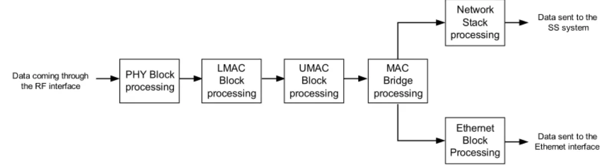
Figure 20: Ethernet Data: processing order...41
Figure 21: RF Data: processing order...42
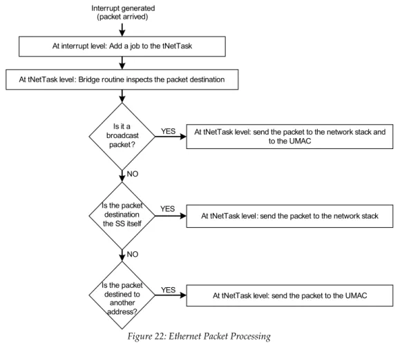
Figure 22: Ethernet Packet Processing...43
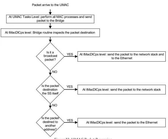
Figure 23: UMAC Packet Processing...44
Figure 24: WiRIA SS Software Architecture...46
Figure 25: MAC Bridge Architecture...47
Figure 26: Air interface: UMAC data...50
Figure 27: Air interface: SS system data to UMAC ...51
Figure 28: Ethernet interface: Data entering the Ethernet...52
Figure 29: Field Tests Testing Scenario...63
Figure 30: Test Scenario for measuring BE Delay alone...64
Figure 31: Test Scenario for measuring rtPS alone...64
Figure 32: Test Scenario for measuring BE Delay with rtPS traffic on the system...65
Figure 33: WiRIA SS Maximum Data Rate for the BE Class...68
Figure 34: WiRIA SS Maximum Data Rate for the rtPS Class...68
Figure 35: Redline SS Maximum Data Rate for the BE class...68
Figure 36: Redline SS Maximum Data Rate for the rtPS Class...68
Figure 37: WiRIA BE and rtPS Maximum Delay...70
Figure 38: WiRIA BE and rtPS Minimum Delay...70
Figure 39: WiRIA BE and rtPS Average Delay...70
Figure 40: WiRIA BE and rtPS Standard Deviation...70
Figure 41: WiRIA BE and rtPS Jitter...70
Figure 42: Redline BE and rtPS Minimum Delay...72
Figure 43: Redline BE and rtPS Maximum Delay...72
Figure 44: Redline BE and rtPS Average Delay...73
Figure 45: Redline BE and rtPS Standard Deviation...73
Table 1: WiMAX development kits comparison...33
Table 2: Fujitsu Software: VxWorks System Tasks...40
Table 3: Fujitsu Software: UMAC Tasks...41
Table 4: Fujitsu Software: User Application Task...41
Table 5: WiMAX SS VxWorks System Tasks...52
Table 6: WiMAX SS Ethernet Task...53
Table 7: WiMAX SS MAC Bridge Task...53
Table 8: Other WiMAX SS Tasks...54
Table 9: RF parameters measured in the Field Fixed Tests...66
Table 10: Throughput measured in the Field Fixed Tests...66
Table 11: BE Delay using the WiRIA SS...69
Table 12: rtPS Delay using the WiRIA SS...69
Table 13: rtPS Delay with 8192 kbps BE traffic load on DL and UL separately...71
Table 14: BE Delay using the Redline SS...72
List of Acronyms
ABS Anti-lock Breaking System
ACK Acknowledgment
AES Advanced Encryption Standard AMC Adaptive Modulation and Coding API Application Programming Interface ARQ Automatic Repeat Request
ASIC Application Specific Integrated Circuit
BE Best Effort
BPSK Binary Phase Shift Keying
BS Base Station
CBC Cipher Block Chaining CID Connection Identifier
CINR Carrier to Interference-plus-Noise Ratio CLI Command Line Interface
COOPERS CO-operative Systems for Intelligent Road Safety
CP Cycle Prefix
CPS Common Part Sub-Layer CRC Cyclic Redundancy Check CS Convergence Sub-Layer
CVIS Cooperative Vehicle-Infrastructure Systems DCD Downlink Channel Descriptor
DES Data Encryption Standard
DHCP Dynamic Host Configuration Protocol DL-MAP Downlink MAP
DSA Dynamic Service Addition DSC Dynamic Service Change DSD Dynamic Service Deletion
DSRC Dedicated Short Range Communication ECU Electronic Control Unit
ertPS Extended Real-Time Polling Service ESP Electronic Stability Program
FCH Frame Control Header FDD Frequency Division Duplex FEC Forward Error Correction FFT Fast Fourier Transform
FTP File Transfer Protocol
GPIO General Purpose Input Output GPS Global Positioning System H-FDD Half Frequency Division Duplex HARQ Hybrid Automatic Repeat Request HCS Header Check Sequence
HTTP Hipertext Transfer Protocol ICMP Internet Control Message Protocol IDE Integrated Development Environment IF Intermediate Frequency
LMAC Lower Medium Access Control LOS Line of Sight
MAC Medium Access Control MSDU MAC Service Data Unit NLOS Non-Line of Sight
nrtPS Non-Real-Time Polling Service
OBU On-Board Unit
OFDM Orthogonal Frequency Division Multiplex OFDMA Orthogonal Frequency Division Multiple Access
OS Operating System
PDU Protocol Data Unit
PHS Payload Header Suppression PHSF Payload Header Suppression Field PHSI Payload Header Suppression Index PHSM Payload Header Suppression Mask PHSS Payload Header Suppression Size PHSV Payload Header Suppression Valid
PHY Physical
PKM Privacy Key Management PMP Point to Multipoint
PS Physical Slot
PSAP Physical Service Access Point QAM Quadrature Amplitude Modulation QoS Quality of Service
QPSK Quadrature Phase Shift Keying RCC Regional Control Center
RF Radio Frequency
RSSI Received-signal-strength-indication
RSP Response
RSU Road Side Unit
RTOS Real-Time Operating System rtPS Real-Time Polling Service SA Security Association SAP Service Access Point SDU Service Data Unit
SF Service Flow
SNMP Simple Network Management Protocol
SoC System on Chip
SPI Serial to Parallel Interface SS Subscriber Station TCS Traction Control System TDD Time Division Duplex TDM Time Division Multiplex TDMA Time Division Multiple Access
TEK Encryption Key
TFTP Trivial File Transfer Protocol
UART Universal Asynchronous Receiver Transmitter UCD Uplink Channel Descriptor
UGS Unsolicited Granted Service
UL Uplink
UL-MAP Uplink MAP
UMAC Upper Medium Access Control URI Uniform Resource Identifier USDOT U.S. Department of Transportation V2I Vehicle to Infrastructure
V2V Vehicle to Vehicle VSC Virtual Sub-Center
Assessing WiMAX for vehicular communications applications
Chapter 1
Introduction
1.1 . Motivation
Nowadays, road safety is a mainstream topic in society all over the world. The number of car accidents in the Portuguese roads in 2006 reached 35,680 and has involved more than 47,000 people, killing 850 [1]. In the European context, in 2005 more than 40,000 people were killed in road accidents [2]. This scenario has a dramatic and unacceptable impact in terms of human life losses and injuries as well as in the economy. In pair with initiatives associated with driver behavior changes, reduction of speed limits, etc., technical aids, supporting active and dynamic prevention of car accidents, are being considered as a decisive way of achieving a reduction on the road accidents as well as on its impact in terms of injuries and fatalities. The development and deployment of such mechanisms can have a positive impact and can help to reduce the road fatalities and injuries.
1.2 . Road Safety and Vehicular Communications
In the last decades, a substantial effort has been devoted to study and develop mechanisms that improve road safety. The initial efforts have been directed mainly to improvements on in-vehicle subsystems and operate entirely based on local sensors and actuators. Examples are the Anti-lock Breaking System (ABS), which avoids the wheel skidding when the driver actuates the breaks, the Traction Control System (TCS), which prevents traction wheel skidding during acceleration, the Electronic Stability Program (ESP), which actively corrects the vehicle path according to the steering wheel input. However, these mechanisms are merely reactive, not being able to foresee potentially dangerous situations beyond their environment, and so, despite being extremely useful, exhibit a limited scope of coverage.
One of the approaches that can achieve a better scope of coverage and then enhance road and traffic safety is improving the sensing capabilities, allowing the drivers to be informed in advance of abnormal and potentially dangerous situations. This scenario becomes possible if drivers and vehicles can communicate with each other and with roadside base stations. Those mechanisms could have a major importance on many common but potentially dangerous daily road situations like reporting accidents, approach of traffic jams or other obstacles in highways, approach of emergency vehicles, lane changes, cross of highway intersections, etc. Consequently the drivers’ radius of perception is effectively enlarged and so knowledge about potentially dangerous situations is anticipated, improving the capability of the driver in carrying out correct maneuvers and avoiding accidents.
Two possible communication architectures can be used to achieve these purposes: Vehicle to Vehicle
communication (V2V) and Vehicle to Infrastructure communication (V2I). The V2V communication
consists on the transmission of road safety information between vehicles on the road and V2I communication consists in using a fixed road side station to communicate with the vehicles in order to transmit safety information (sometimes the I2V term is used to characterize the communication from the infrastructure to vehicles). This document is focused on the V2I communication system that is composed by: the On–Board Unit (OBU) and Road–Side Unit (RSU). The OBU is the unit that resides on each vehicle and that allows the communication with the RSU that is a unit on the side of the road which can send safety related information or other to the OBU (Figure 1).
Figure 1: Coexistence of V2I and V2V [3]
The mobility constrains associated with these two vehicular communication architectures open a door to the usage of wireless technologies. Several of them, like GSM, GPRS, WiFi, BlueTooth,
Introduction
Dedicated Short Range Communications (DSRC) and others can and have been explored to perform V2I communication. The V2I applications require a communication system capable of providing information to the vehicles on the road taking in account requirements such as bandwidth, maximum latency, jitter, timeliness and coverage area.
1.3 . WiMAX as Vehicular Communication Candidate
One of these technologies that, to our best knowledge, was not yet adequately explored in this type of applications is WiMAX, which has promising features (e.g., range, bandwidth and real-time guarantees) for implementing V2I/I2V communication and therefore is a candidate to be evaluated. WiMAX, the Worldwide Interoperability for Microwave Access, is a standards-based wireless technology, based on the IEEE 802.16 [4] standard that allows fixed and mobile access with Non-Line Of Sight (NLOS) reaching data rates of 40 Mbps in a 3Km to 10 Km cell, per channel [5]. With this technology it is possible to have Quality of Service (QoS) in the Medium Access Control (MAC) layer. It is also possible with WiMAX to have bidirectional communication with configurable percentage of transmit/receive time (in time division duplex mode – TDD). So, this technology could be used for some specific vehicular applications like the following ones:
1. Safety Warning : The driver could get messages about dangerous situations that he/she is about to face;
2. Assisted Driving : The driver could be helped and assisted in order to take the correct behavior when facing a potential dangerous situation;
3. Traffic Management : The V2I communication could be used to avoid or solve traffic jams informing drivers not to go along the problematic areas.
4. Commercial Applications : video, music, and others.
1.4 . Objectives and Document Outline
This dissertation introduces WiMAX as a vehicular communication technology, concretely in V2I/I2V communication, and discusses its suitability to support the application domains above identified. It is the main objective to study the timing requirements of several vehicular applications and to understand the impact of the introduction of road safety services on a WiMAX equipment developed on WiRIA project where the author is collaborating. It will be performed a study on the impact of the introduction of these services on the WiMAX equipments scheduling and try to understand which safety services can be addressed by these equipments, taking in account real-time requirements like latency and jitter.
The work that is being performed is related to the WiRIA project that aims to project, develop and test a WiMAX Subscriber Station (SS) to operate with a commercial WiMAX Base Station. This project is funded by TELESAL and is coordinate by Institute of Telecommunication, University of
Aveiro and PT Inovação. The work performed to assess WiMAX as a vehicular communication technology is also funded by BRISA, S.A. A paper, which title is “Assessing WiMAX for vehicular communications”, related with the work performed on this dissertation was already accepted for presentation at the CONTROLO’2008 - The 8th Portuguese Conference on Automatic Control to be held in Vila Real, Portugal from 21 to 23 July 2008.
The remaining of this document is organized as follows: Chapter 2 presents a brief survey on the state-of-the-art of V2I and V2V, with particular focus on European projects; Chapter 3 provides some background information on the WiMAX wireless technology; Chapter 4 shows the WiMAX development platforms that were studied in order to develop the WiMAX SS; Chapter 5 provides a explanation about the hardware/software architecture provided with the WiMAX development kit chosen; Chapter 6 presents the new software architecture developed to create a real WiMAX SS solution; Chapter 7 presents the specific V2I applications studied and their requirements followed by the specification and results obtained from several tests performed using WiMAX technology; Chapter 8 presents the conclusions of the work performed and propose future work to be done in this context.
Assessing WiMAX for vehicular communications applications
Chapter 2
State-of-the-art
The concern of reducing road injuries and fatalities is present all over the world and therefore many initiatives are being developed to pursue this objective. So, a large number of projects related to road safety are currently under way, mainly in the USA, Japan and Europe, and almost all of them use V2V and V2I communications as ways of achieving a road accidents reduction. In this chapter, the focus will be mainly directed to the European projects that are being funded by the European Commission.
2.1 . Introduction
All over the world, many initiatives are being deployed with the purpose of reducing car accidents on the roads. To achieve this objective, it is necessary to supply specific safety services using V2V
and V2I communication architectures. Some of these services can be provided using both V2V and V2I communication systems but others present constrains that require using one specific architecture. Typically, safety services related to static dangerous situations such as narrow curves, tunnels, bridges, work on the road or bad weather conditions can be addressed using V2I communication because the infrastructure intrinsically knows their dangerousness. On the other hand, information about dangerous situations that appears suddenly such as a sudden car break, formation of ice on the road or the approximation of priority vehicles can be shared among vehicles using a V2V architecture to provide safety warnings to the vicinity as soon as possible.
All of the services described above present requirements of mobility, reliability and timeliness in order to be useful and then improve safety on the roads. In the following sections, there are presented some on-going projects that have the objective to fulfill the requirements identified using different approaches to address road safety issues.
2.2 . European Projects
The European Commission and the automotive industry are strongly committed to improve road safety and reduce the number of accidents in European roads. The initiative eSafety [6] reflects this will “eSafety, the first pillar of the Intelligent Car Initiative, is a joint initiative of the European
Commission, industry and other stakeholders and aims to accelerate the development, deployment and use of
Intelligent Integrated Safety Systems” in [6]. Associated with the eSafety initiative is the eSafety
Forum [2], which has the objective of promoting and monitoring the implementation of the recommendations identified by the eSafety Working Group, as well as support the development, deployment and use of new and intelligent integrated road safety systems. Since 2002, this initiative has funded a number of projects, where the V2V and V2I are the base of several of them.
So, as referred before, the European Commission is funding several projects that use information and communication technologies in intelligent solutions, in order to increase road safety [7]. The projects funding is currently (November 2007) done by the Sixth Framework Program (FP6) which has the objective to promote the scientific and technological bases of industry and encourage its international competitiveness while promoting research activities [8].
2.2.1. COMeSafety
The COMeSafety project [9] has been funded with 1.1M€ and supports the eSafety Forum with respect to all issues related to V2V and V2I communications as the basis for cooperative intelligent road transport systems. It is composed by a projects network depicted in Figure 2.
COMeSafety provides a platform that allows the exchange of information and the presentation of results among the entities shown in Figure 2. Regular electronic newsletters and publications at major conferences and press events complement the dissemination efforts. For European and
State-of-the-art
worldwide harmonization, liaisons are established and workshops are organized to bring together the eSafety Forum and all stakeholders. COMeSafety provides an open integrating platform, aiming for the interests of all public and private stakeholders to be represented. [9]
2.2.2. COOPERS
The CO-operative Systems for Intelligent Road Safety (COOPERS) project [10] is funded with 9.8M€ by FP6 and has the ambition to connect vehicles to road infrastructures on motorways. This link will allow the exchange of data and information to increase the safety in specific road segments (Figure 3). The V2I communication in this respect will significantly improve traffic control and safety via effective and reliable transmission of data fully adapted to the local situation of the vehicle (ensemble of vehicles) as depicted in [10].
COOPERS follows a 3-step approach for implementing V2I communication: improvement of road sensor infrastructure and traffic control applications for more precise situation based on traffic information and driver advisement; Establishment of a link between road tolling systems and V2I concept; Development of a communication concept and applications able to cope with the V2I requirements in terms of reliability, real time capability and robustness [10].
Figure 3: COOPERS vision [10] Figure 2: COMeSafety projects Network [9]
So, the mission is to define and develop services and equipment to provide bi-directional links between the infrastructure and vehicles (V2I) using an open standardized wireless communication technology. A stable link needs to be established in order to ensure the transmission of real-time location-based safety related information on the current traffic status [10]. The highest effect of V2I communications will be achieved in areas of dense traffic, where the risk of accidents and traffic jams is extremely high [10].
2.2.3. SAFESPOT
The SAFESPOT project [11] is also funded by FP6 with 20.59M€ and has the purpose of preventing road accidents developing a “Safety Margin Assistant” that detects in advance potentially dangerous situations and extends “in space and time” drivers’ awareness of the surrounding environment. The Safety Margin Assistant will be an Intelligent Cooperative System based on V2V and V2I communication. It proposes an open, flexible and modular architecture and communication platform, where both the infrastructure and the vehicles are sources and destinations of safety-related information and develop a new generation of infrastructure-based sensing techniques.
The specific objectives on SAFESPOT project are to improve the range, quality and reliability of the safety-related information available to 'intelligent vehicles' by providing “extended co-operative awareness” through the real time reconstruction of the driving context and environment, to support drivers preventively to the proper manoeuvres in the different contexts, to optimize the intervention of vehicle controls with respect to critical situations, to manage existing incidents to minimize further negative safety impact, to open the development of new safety applications based on the cooperative approach and to increase the safety for all road users (including pedestrians and cyclists).
SAFESPOT defines two types of test scenarios:
1. Static black spots or "static risky conditions", which are road scenarios intrinsically dangerous, statistically identifiable, such as narrow curves, tunnels and bridges; these road scenarios are typically addressed by V2I communication.
2. Dynamic black spots or "dynamic risky conditions", which are where the driving scenarios may become unexpectedly and suddenly dangerous (like ice conditions, a queue behind a curve, a vehicle that suddenly harshly breaks, presence of vehicles in blind spots, etc.). This type of scenarios are typically addressed using V2V and V2I communication.
The technological challenges faced by this project are the availability of a reliable, fast, secure and potentially low cost protocol for local vehicle to vehicle and vehicle to infrastructure communication. A possible candidate is the radio technology, currently under standardization, IEEE 802.11p.
State-of-the-art
2.2.4. CVIS
The Cooperative Vehicle-Infrastructure Systems [12] project aims to design, develop and test new technologies needed to allow vehicles to communicate with each other and with the nearby roadside infrastructure. The main objective is to create standardized in-vehicle and roadside modules capable of communicating continuously and seamlessly using a wide range of communication media, including mobile cellular and wireless local area networks, short-range microwave (Dedicated Short Range Communications - DSRC) or infrared (Figure 4).
It is also the intent of this project to develop techniques for better vehicle localization and improved local dynamic maps, using for that satellite navigation and state-of-the-art methods for localization referencing. Define and test new systems for cooperative traffic and network monitoring, to use both in vehicle and roadside equipment, as well as detecting incidents instantly and anywhere, are also objectives of CVIS. To achieve these objectives CVIS will build on the latest global communication standards to develop its world.
2.2.5. COM2REACT
Another FP6 funded project with 3M€ is COM2REACT [13]. Its vision is to create a three level architecture in order to improve road efficiency and safety: a low level control that is done inside each vehicle; a middle level control provided by a local center to the vehicles in the area; and a high level control of a metropolitan or urban area provided by a regional center [13].
The main feature of COM2REACT is a virtual traffic control sub-centre (VSC), which controls a moving group of vehicles in close proximity (medium level). This VSC will be inside a car that is moving and uses V2V communication to send and receive information providing safety instructions to the vehicles that are in its vicinity (Figure 5). The VSC uses V2I communication to
send traffic related information to the regional control center (RCC) and also receives from it some data to send to the vehicles that are on the area. The role of VSC is set, unnoticeable by the driver, to one of the vehicles in the group according to rules embedded in all COM2REACT vehicles. It is also wanted to adapt existing communication technologies to perform these communications (ex. WiFi, GPRS) [13].
2.3 . Other European Projects
There are other European projects funded by FP6 that have the purpose of improving road safety and reducing injuries and fatalities. All of them relies on the concept of vehicular communication and accept that V2V and V2I communication will be a central part on the road safety system in the future. For example, one of the objectives of the PReVENT Integrated Project [14] is to develop, demonstrate, test and evaluate preventive safety applications, using advanced sensor, communication and positioning technologies integrated into on-board systems for driver assistance and then communication technologies are needed to improve the detection, location and evaluation of hazards [14]. There are also projects that want to solve security issues in vehicular communications like SEVECOM project [15]. This project has the vision that vehicular communication and inter-vehicular communication bring the promise of improved road safety and optimized road safety and then aims to identify a variety of threats to vehicular network, to specify an architecture, security mechanisms and cryptographic primitives to be used in vehicular networks.
Beside the European projects referred in this document there are much more (some of them funded by FP6 and some don't) currently under way and that want to address road safety. Looking at them we can find a common thought: vehicle to vehicle communication and vehicle to infrastructure communication will be an essential part of the road security systems in the future.
State-of-the-art
2.4 . More Initiatives
The effort of improving road safety is not present only in Europe. There are also a lot of initiatives mainly in the United States of America and in Japan that aims to reduce road injuries and fatalities. For example, in the USA, this promise is being carried out mainly by the U.S. Department of
Transportation (USDOT) and some partners. Projects like VII [16] defines the establishment of V2V
and V2I communication capability nationwide and has the purpose to enable a number of new services that provide significant mobility, safety and commercial benefits.
2.5 . Conclusion
The brief survey on eSafety projects above presented permits concluding that the wireless communication technologies will be at the center of all road security systems in the future. Until now, several research directions have been pursued in this domain. Some projects are addressing the possibility of using standard technologies, such as Wi-Fi, BlueTooth, GSM or UMTS while others are focusing the development of custom technologies, eventually derived from standard ones (DSRC).
The initiatives that are studying standard technologies or derived to perform vehicular communications face several challenges when trying to supply safety vehicular services. These challenges are related to the specific requirements of this type of communication scenario: (1) mobility: the relative position between the vehicles and road fixed station varies during the transmission; (2) timeliness: it is necessary to guarantee that the safety information is delivered to vehicles in appropriate times to not compromise its usefulness; (3) coverage area: with an extended coverage area it is possible for the information transmitted to reach vehicles sooner decreasing the number of RSU's needed and associated costs and (4) bandwidth: it is important to guarantee enough bandwidth to provide several simultaneous safety services to the vehicle in a certain coverage area.
The standard technologies were not projected for this type of application and therefore present some weaknesses in some of the requirements above identified. For example, DSRC (based on WiFi) presents a large available data rate (bandwidth) that can reach 27 Mbps but has a small/medium coverage area (1000m maximum) then increasing the number of RSU's needed and associated costs. BlueTooth present a small coverage area (can reach 100m for class 1) and a low data rate that can only reach 3 Mbps despite of existing new proposals for increasing it. Cellular networks like GSM or UMTS present a large coverage because they are widely deployed, however they present a small available bandwidth that can reach only 10 Mbps (theoretically) in the better case (UMTS).
So, it is possible to see that none of the standard or derived technologies mentioned matches perfectly the V2I applications requirements and that, until now, no clear winner has emerged, and so the assessment of wireless technologies is still an open issue. In this way, WiMAX can also be a candidate to perform V2I communication because some of its features seem to be suitable to supply
this type of applications: the coverage area of WiMAX can reach tens of km in an LOS environment providing data rates of 20 Mbps (using a 7MHz channel bandwidth). However, the characteristic that distinguish the most this technology from the other ones is the fact it has QoS mechanisms implemented in the MAC layer that allow to have traffic differentiation. So, it is possible to prioritize time critical information services without the necessity of implementing further mechanisms. Therefore, WiMAX seems to have the necessary characteristics to be evaluated as a possible solution for V2I communication.
Assessing WiMAX for vehicular communications applications
Chapter 3
Overview of WiMAX
WiMAX, the Worldwide Interoperability for Microwave Access, is a telecommunication technology aimed at providing wireless data over long distances in a variety of ways, from point-to-point links to full mobile cellular type access. This technology has some extremely promising characteristics, such as the support of different QoS levels and traffic classes, including real-time guarantees, high range and bandwidth, and thus it is a strong candidate for V2I communication. The reminder of this section presents a brief characterization of the WiMAX technology and the 802.16 standard in which is based on.
3.1. Background
The IEEE 802.16 [17] group was formed in 1998 to develop an air-interface standard for wireless broadband [18]. This group initial objective was the development of a Line-Of-Sight (LOS)-based
point-to-multipoint (PMP) wireless broadband system for operation in the 10GHz–66GHz, which resulted in the original 802.16 standard, published in December 2001. This standard was based on a single-carrier physical (PHY) layer with a burst time division multiplexed (TDM) MAC layer. Subsequently, the IEEE 802.16 group produced the 802.16a amendment, to include Non-LOS (NLOS) applications in the 2GHz–11GHz band, using an orthogonal frequency division multiplexing (OFDM)-based physical layer. In 2004, a new standard, called IEEE 802.16-2004 [19], replaced all prior versions and formed the basis for the first Fixed WiMAX solution [20]. In December 2005, the IEEE group completed and approved IEEE 802.16e-2005 [21], an amendment to the IEEE 802.16-2004 standard that added mobility support, which forms the basis for the Mobile WiMAX [22].
The WiMAX Forum [23] is an industry-led, non-profit organization formed to certify and promote the compatibility and interoperability of broadband wireless products based upon the harmonized IEEE 802.16/ETSI HiperMAN standard [20]. A WiMAX Forum goal is to accelerate the introduction of these systems into the marketplace [20]. The WiMAX Forum has also established some profiles for certification. There are different profiles for Fixed WiMAX and for Mobile WiMAX. Each profile sets well defined values for the frequency, channel bandwidth, OFDM Fast Fourier Transform (FFT) size and duplexing, to allow equipments from different manufacturers to work together, under the condition of respecting the same profile, achieving then interoperability.
3.2. Fixed and Mobile WiMAX: Main Features
As stated in previous section, WiMAX wireless technology has two different versions: Fixed and Mobile. These two versions are targeted for different applications and despite of having several similarities they present some technical differences. Their features are presented in a brief survey next, mentioning which are the main differences between them when necessary [18]:
● OFDM-based physical layer - scheme that offers a robust behavior in presence of multipath radio signal propagation, allowing WiMAX to operate in NLOS conditions. ● Orthogonal frequency division multiple access (OFDMA) - Mobile WiMAX uses OFDM
as a multiple-access technique, whereby different users can be granted with different subsets of OFDM tones. This is not applicable for fixed WiMAX.
● Support for TDD and FDD - the WiMAX supports time division duplexing (TDD), frequency division duplexing (FDD) and Half-FDD.
● Very high peak data rates - the peak PHY data rate can be as high as 74Mbps when operating using a 20MHz wide spectrum (in both directions, downlink and uplink).
● Scalable bandwidth and data rate support - a scalable physical-layer architecture that allows for the data rate to scale easily with the available channel bandwidth. This scalability is supported in the OFDMA mode (Mobile WiMAX), where the FFT size may be scaled based on the available channel bandwidth. This is not applicable for fixed WiMAX. ● Adaptive modulation and coding (AMC) - the WiMAX supports a number of modulation
Overview of WiMAX
on a per user and per frame basis, based on the instantaneous channel conditions. AMC is an effective mechanism to maximize throughput in a time-varying channel.
● Link-layer retransmissions - for connections that require enhanced reliability, WiMAX supports automatic retransmission requests (ARQ) at the link layer. ARQ-enabled connections require each transmitted packet to be acknowledged by the receiver so unacknowledged packets are retransmitted. The mobile WiMAX optionally supports hybrid-ARQ, which is an effective hybrid between FEC and ARQ.
● Flexible and dynamic per user resource allocation - Both uplink and downlink resource allocation are controlled by a scheduler in the BS. Capacity is shared among multiple users on a demand basis, using a burst TDM scheme. When using the OFDMA-PHY mode, multiplexing is additionally done in the frequency dimension, by allocating different subsets of OFDM subcarriers to different users. The IEEE 802.16 allows broadcast and multicast messages, which optimizes the use of the spectrum.
● Quality-of-service support - The WiMAX MAC layer has a connection-oriented architecture that is designed to support a variety of applications, including voice and multimedia services. The system offers support for constant bit rate, variable bit rate, real-time, and non-real-time traffic flows, in addition to best-effort data traffic.
● Robust security - WiMAX supports strong encryption and has a robust privacy and key-management protocol.
● Support for mobility - The mobile WiMAX variant of the system has mechanisms to support secure seamless handover for delay-tolerant full-mobility applications. The system also has built-in support for power-saving mechanisms that extend the battery life of handheld subscriber devices. Physical-layer enhancements, such as more frequent channel estimation, uplink sub channelization, and power control, are also specified in support of mobile applications.
● IP-based architecture - The WiMAX Forum has defined a reference network architecture that is based on an all-IP platform. All end-to-end services are delivered over an IP architecture relying on IP-based protocols for end-to-end transport, QoS, session management, security, and mobility.
3.3. Basic Topology
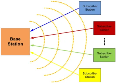
The IEEE 802.16 standard defines two different basic topologies: Point-to-Multipoint (PMP) and Mesh but only the first one is used in the WiMAX technology. This kind of topology consists in two logical entities: the Base Station (BS) and the Subscriber Station (SS) [24]. In this case, the BS and SS are in a master-slave relationship, where the SS must follow the medium access rules defined by the BS (Figure 6). It is important to refer that all the communications are always performed between a BS and SS and vice-versa.
The 802.16-2004 technology is exclusively connection-oriented. Therefore, all transmissions are based on a connection and no packets are allowed to traverse the wireless link without a specific connection being previously allocated. A connection is, by definition, a unidirectional mapping
between the BS and the SS MAC layers for the purpose of transporting service flows traffic. To uniquely identify a connection, a 16-bit Connection Identifier (CID) is used [25].
The transmission performed by the BS (downlink) and by the SS's (uplink) can be done at the same time in different frequencies or at different times in the same frequency. The first one is called
Frequency Division Duplex (FDD) and will be not explored in this study because it brings more
hardware complexity (two radio modules necessary). The second one is Time Division Duplex (TDD) and the transmission done by the BS and SS's are at the same frequencies but occur in different times. Therefore there is always a defined time to the downlink transmission direction (downlink sub-frame) followed by an uplink transmission time (uplink sub-frame) like shown in Figure 7. The downlink sub-frame and uplink sub-frame form the transmission frame and its duration is fixed. However the time duration of the downlink and uplink sub-frames are adaptive.
The BS transmission is done in a Time Division Multiplex (TDM) fashion providing information to each registered SS in different times in the downlink sub-frame. In this type of topology there is only one BS and therefore all SS's registered in this BS receive all transmissions. So, each SS needs to select the information which is directed to it discarding the other. This selection is performed by inspecting the Connection Identifier (CID) of each MAC Protocol Data Unit (PDU) sent. On the other hand, the transmission done by the SS's is performed on a Time Division Multiple Access (TDMA), that is, in each moment only one SS can transmit and those moments are granted by the BS. These BS grants are based on the scheduling service associated to each flow of packets implementing, in this way, service differentiation. This type of communication is commonly known as Master – Slave communication.
In order to perform the communication explained above it is necessary to control the access to the medium (air) by all the network entities defining the rules to be followed on each transmission. It is also necessary to implement mechanisms that make the transmissions reliable, i.e., that give some
Figure 6: PMP Topology Base Station Subscriber Station Subscriber Station Subscriber Station Subscriber Station
Overview of WiMAX
assurance that the information transmitted reaches its destination and that the receiver can understand it. The network layers defined in the IEEE 802.16 address those issues.
3.4. Network Layering
The 802.16 standard in which WiMAX is based defines both the Medium Access Control (MAC) and
Physical (PHY) layers. The protocol stack is depicted in Figure 8. It is possible to see that the MAC
layer is divided in three sub-layers: (1) The Convergence Sub Layer that is responsible for interfacing the MAC layer with the higher network layer performing all operations related to it; (2) The Common Part Sub Layer that performs all the more important MAC functions and (3) the Security Sub Layer that is responsible for all issues related to encryption and authentication. Below the MAC Layer there is the PHY Layer that performs the necessary operations to transmit reliably the information over the air.
3.4.1. Physical Layer
The PHY Layer is responsible for accepting the data bursts from the MAC Layer performing several operations on it like Forward Error Correction (FEC) and modulation and creating the symbols to be sent over the air (it is also responsible to perform the reverse process when receiving data from the air).
Figure 7: TDD Duplexing
Figure 8: IEEE 802.16 Network layer
Physical Layer (PHY)
MAC Security Sub Layer
MAC Common Part Sub Layer
MAC Convergence Sub Layer
MAC
Before explaining some of the processes executed in the PHY it is important to refer that the IEEE 802.16 standard defines four different PHY Layers: (1) WirelessMAN SC (11 – 66 GHz); (2) WirelessMAN SCa (2 – 11 GHz); (3) WirelessMAN OFDM (2 – 11 GHz) and (4) WirelessMAN OFDMA (2 – 11 GHz). However the WiMAX technology uses only two of them: WirelessMAN OFDM for the Fixed WiMAX and WirelessMAN OFDMA for Mobile WiMAX and therefore those are focused on this section.
When the OFDM or OFDMA PHY Layer receives MAC data through the PHY Service Access Point (SAP) it first performs the operations depicted in the transmission chain (Figure 9).
It is possible to see the different processes done by the PHY Layer. The randomization block is useful to avoid long sequences of consecutive ones or zeros. Then the randomized information is sent to the FEC encoder that consists in applying convolutional codes to the information (different mandatory codes for WirelessMAN OFDM and WirelessMAN OFDMA) and after this, the information is sent to the interleaving block that gives protection against long sequences of errors which are difficult to correct in the receiver. Then the repetition block (only present in WirelessMAN OFDMA) increases the signal margin further over the modulation and FEC mechanisms and for last, modulation is performed. The modulation is one of the four digital modulation used in WiMAX (BPSK, QPSK, 16QAM and 64QAM). It is the MAC Layer that controls which modulation should be used for each burst.
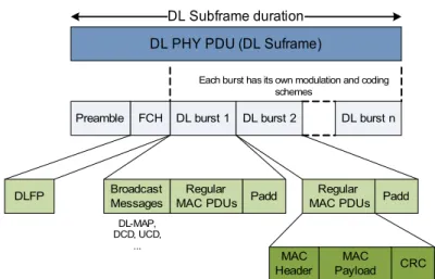
After the modulation block, the information is sent to a stage related to the construction of the OFDM symbols that give protection against multipath transmission problems and then OFDM symbols are grouped to form the frame that will be sent over the air. It is important to say that the basic unit of time is the Physical Slot (PS) and that corresponds to four OFDM symbols. If the duplexing mode used is FDD then there will be a frame for the uplink and another for the downlink having the same time duration. However if TDD duplexing mode is used then there will be only one frame and this one will be divided in two sub-frames: downlink and uplink (see Figure 7). The uplink and downlink sub-frames are different for OFDM and OFDMA. In Figure 10 it is possible to see the OFDM downlink sub-frame constitution.
The preamble is used to synchronize the SS's that want to read the downlink frame. The Frame
Control Header (FCH) is one OFDM symbol long and is transmitted at the more robust profile
(BPSK ½) and then all downlink bursts are transmitted. The broadcast messages are the first to be transmitted followed by the multicast or unicast bursts in a decreasing order of robustness. The uplink sub-frame (Figure 11) is constituted by two contention slots where collisions can happen: initial ranging and bandwidth request. The first is used by the SS's to join the network and the
Figure 9: PHY Transmission Chain
Randomization FEC Encoder(CC, Turbo
Code) Interleaving Repetition Modulation
MAC Data
Overview of WiMAX
second is used by the SS's to send bandwidth requests to the BS. After these two slots, all the uplink bursts are sent to the BS, one for each SS. The two contention slots and uplink bursts are known by the SS's because this information is previously sent by the BS in broadcast messages.
3.4.2. MAC Security Sub-Layer
The MAC Security Sub-Layer provides authentication and data encryption functions. These functions afford privacy to subscribers and protect operators from theft of service. Their purposes are achieved by encrypting the data between the BS and SS using the Privacy Key Management (PKM) protocol.
In the sending entity, the MAC PDU's are mapped to a Security Association (SA) that defines the encryption processing to be done. In the receiving entity the reverse process is done after determining the CID and SA. An SA is a set of security information that is shared between the BS and SS using the PKM protocol. Some of the information included in the SA is the cryptographic suite to use, the encryption keys (TEK's) along with their lifetime. Only the payload of MAC PDU is encrypted.
The standard defines two cryptographic suites to be used: Data Encryption Standard (DES) in Cipher
Block Chaining (CBC) mode and Advanced Encryption Standard (AES) in Counter with CBC – MAC
Figure 10: Downlink sub-frame constitution
DL PHY PDU (DL Suframe) DL Subframe duration
DL burst 1 DL burst 2 DL burst n FCH
Preamble
DLFP BroadcastMessages MAC PDUsRegular Padd MAC PDUsRegular Padd
MAC Header
MAC Payload CRC
Each burst has its own modulation and coding schemes
DL-MAP, DCD, UCD,
...
Figure 11: OFDM Uplink Subframe Intial Ranging Contention Slot Bandwidth Request Contention Slot UL – PHY PDU SS 1 UL – PHY PDU SS N UL Subframe Duration
(CCM) mode. The first one provides a security that is not very strong because the keys are too short to be secure. The second one is considered to be more secure since the keys are longer. There are also processes to perform key management and certain rules need to be followed by SS's and BS's to solve security issues but they will be not explored in this document.
So, the MAC Security Sub-Layer is responsible to encrypt the payload of the MAC PDU's and to provide the mechanisms to manage all the security information shared between the SS and the BS.
3.4.3. MAC Common Part Sub-Layer
The CPS is the second sublayer from the MAC layer. It receives packets arriving from the
Convergence Sub-Layer (CS) and it is responsible for a set of functions, such as addressing,
construction and transmission of the MAC PDU's, implementing the uplink scheduling services, bandwidth allocation, request mechanisms, contention resolution, among others. The 802.16-2004 MAC is connection oriented since all services are mapped to a connection. Associated with each connection is a service flow (SF). Service flows provide a mechanism for uplink and downlink QoS management. [25]
The first concept that needs to be introduced is the 802.16 connection. A connection is an unidirectional mapping between the BS and SS identified by a CID. Therefore all MAC tasks are performed based on a connection except in the initial ranging and authentication processes. In the initialization process, three pairs of management connections (each pair has an uplink and a downlink connection) are established for each SS: (1) the basic connection that is used for short and time critical MAC management messages, (2) the primary connection that provides a way to transport longer and delay tolerant MAC management messages and (3) the secondary management connection to transfer standard-based management messages (optional). Other connections can be established after like broadcast, multicast polling or transport connections. The broadcast connection is used to send management messages to all SS's, the multicast polling connection is used by the SS's to join multicast groups and request bandwidth, and the transport ones are used to users traffic.
The MAC Layer is responsible to construct each MAC PDU associated with a certain connection. The MAC PDU format is depicted in Figure 12. It consists in a fixed-length header, a variable length payload and an optional Cyclic Redundancy Check (CRC) field. The MAC header can assume two different formats defining that way two different types of MAC PDU: (1) Generic MAC Header or (2) Bandwidth Request Header.
Figure 12: MAC PDU format
Overview of WiMAX
The Generic MAC Header is used by MAC PDU's that transport data coming from the CS layer (users data) or MAC management messages and consists in a MAC Header with the payload and a CRC field. When a MAC PDU is built with information coming from the CS layer then a MAC SDU can be divided in several MAC PDU's (fragmentation) or several MAC SDU's can be grouped in one MAC PDU (packing). It is also possible to agglomerate several MAC PDU's to be transmitted in the same burst (concatenation). The Bandwidth Request Header is used by the SS's to request additional bandwidth and shall not have any payload nor CRC field.
The MAC management connections established in the initialization process (broadcast, basic, primary, ...) transmits only MAC management messages. Those messages are transported in the payload of a Generic MAC PDU and consist in a type field followed by MAC management payload field. The standard defines several management messages and next some of the more important are described:
• Downlink Channel Descriptor (DCD) and Uplink Channel Descriptor (UCD) • Downlink MAP (DL-MAP) and Uplink MAP (UL-MAP)
• Dynamic Service Addition Request (DSA-REQ), Response (DSA-RSP) and Acknowledgment (DSA-ACK)
• Dynamic Service Change Request (DSC-REQ), Response (DSC-RSP) and Acknowledgment (DSC-ACK)
• Dynamic Service Deletion Request (DSD-REQ)
The DCD and UCD are sent periodically by the BS to SS's in order to provide the channel downlink and uplink characteristics respectively. The DL-MAP and UL-MAP messages are also sent periodically by the BS to provide information about the access to downlink and uplink information defining the access to the medium. The DSA, DSC and DSD messages are used to create, change or delete service flows (SF) for user's traffic.
Associated with each SF created using DSA messages there is the scheduling service. In the IEEE 802.16-2004 (Fixed WiMAX) there are four different scheduling policies that can be assigned to a SF and that defines its QoS: Unsolicited Granted Service (UGS), real-time Polling Service (rtPS),
non-real-time Polling Service (nrtPS) and Best Effort (BE). The IEEE 802.16e-2005 added one more scheduling
service: extended real-time Polling Service (ertPS).
● The UGS policy is used for fixed length periodic real time data streams. In this type of service, the BS gives data grants at periodic intervals so the SS's do not need to perform a request for bandwidth thus eliminating latency and overhead. The size of the grants is sufficient to hold the fixed-length data associated with the service flow.
● The rtPS scheduling policy is used to real-time streams that have a variable length and are sent at periodic intervals. The BS provides unicast request opportunities for the SS to request data grants of a specific size. This scheduling service has more overhead that UGS and allows to have a variable packet size improving efficiency for services like MPEG.
● The nrtPS is used for streams tolerant to delay and that have a variable data packet size. The BS provides unicast uplink request opportunities on a regular basis (one second or less). This service is also authorized to use contention request opportunities.
● The ertPS service provides an efficiency that relies on the UGS an rtPS services. The BS provides unicast grants like UGS but the allocated grant size is dynamic like the rtPS protocol.
● The last scheduling service is Best Effort. This kind of service is used by the streams that don't have any requirements. The BS has no obligation to issue request opportunities to CID's associated with a BE service so it is possible to pass a long time before getting any bandwidth.
The scheduling services described in the previous paragraph provide service differentiation because they are treated by the BS differently. It is possible to see that the impact of scheduling services is mainly done on the uplink direction because it is the BS that gives bandwidth to the SS's. The main difference between the scheduling services is in the way that they can ask for bandwidth and how this bandwidth is given by the BS (the BS scheduler decides to which SS the bandwidth is granted). For example, SS's that have UGS connections doesn't have to request bandwidth in order to be given time to transmit.
When an SS needs to request more bandwidth to the BS it can use a Bandwidth Request Header described previously or a PiggyBack Request using a special sub-header. Those requests are done on a connection basis. However the bandwidth grants given by the BS are allocated to the SS's. So, the scheduler in the SS needs to decide to which connection the bandwidth will be given. If a connection has done a request and didn't have received any bandwidth then it repeats the request according to a back off algorithm. In order to send bandwidth requests, the SS's are allocated bandwidth. This process is called polling and the bandwidth can be granted to a specific SS (unicast polling) or to several SS's (multicast polling). When the polling is multicast it is necessary to have a contention resolution algorithm since collisions can occur. There is another polling process that is performed when SS's that have UGS connection explicitly ask to be polled in order to request bandwidth for non UGS connections.
The standard doesn't define multicast or broadcast connections to users' traffic, only for polling or management messages. To achieve that, it is necessary that the BS starts to associate and allocate a regular transport connection to a specifics SS and then assign this same connection, identified by its CID, with the SS's that will be part of the multicast group or to all SS's if broadcast. Other processes need to be controlled by the MAC CPS layer like the Automatic Repeat Request (ARQ) that retransmit MAC PDU's if they are not acknowledge by its receiver.
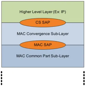
3.4.4. MAC Convergence Sub-Layer
The CS Sub-Layer resides above the MAC CPS Sub-Layer and is responsible to perform all the operations related to higher level protocols. In the transmitter side it should transform a PDU from
Overview of WiMAX
a higher layer protocol into an MAC Service Data Unit (SDU) and assign each MSDU to a particular connection. In the receiver it should perform the inverse operation. It is possible to suppress some header information from the higher layers PDU's in this sub-layer. The IEEE 802.16 standard defines two different CS sub-layers to use: ATM CS and Packet CS. WiMAX technology uses only the Packet CS so this is the one that will be explained next.
As explained before, the CS sub-Layer is responsible for receiving the PDU's from the higher layers through the CS SAP, perform some specific operation creating the MSDU and then deliver it to the MAC CPS Sub-Layer through the MAC SAP like depicted in Figure 13. The main operations performed in this sub-layer are:
– Classification: consists in determining in which MAC connection a particular packet shall be carried;
– Payload Header Suppression (PHS): consists in removing the repetitive part of the higher layer packets header (optional);
Classification is the process in which the MAC SDU's are associated with a connection to exchange traffic between MAC peers. This mapping allows MAC SDU's to be associated with the connection as well as with the service flow and QoS parameters. A classifier is a set of criteria dependent of the higher level protocol (for example IP address), a priority and an associated CID and they are applied to all the packets that enters the 802.16 network. If the packet matches to a criteria then it is delivered to the associated SAP to be sent in the connection identified by the CID. The service flow characteristics in which the connection is associated defines the QoS parameters for the information. The classifier priority is used only to know what classifier should be used when two distinct classifiers can be applied to the same packet. If no criteria could be applied then the packet should be dropped.
Figure 13: Convergence Sub-Layer Service Access Points
MAC Common Part Sub-Layer MAC Convergence Sub-Layer Higher Level Layer (Ex: IP)
CS SAP
![Figure 5: COM2REACT three level architecture [13]](https://thumb-eu.123doks.com/thumbv2/123dok_br/15812153.1080615/30.892.226.644.327.592/figure-com-react-three-level-architecture.webp)
![Figure 16: SQN1010-RD and SQN2010-RD development boards [33]](https://thumb-eu.123doks.com/thumbv2/123dok_br/15812153.1080615/50.892.219.652.726.879/figure-sqn-rd-and-sqn-rd-development-boards.webp)
![Figure 17: Wavesat Development boards[36]](https://thumb-eu.123doks.com/thumbv2/123dok_br/15812153.1080615/52.892.196.673.562.745/figure-wavesat-development-boards.webp)
![Figure 18: Fujitsu hardware structure [39]](https://thumb-eu.123doks.com/thumbv2/123dok_br/15812153.1080615/56.892.192.681.192.512/figure-fujitsu-hardware-structure.webp)