Code Generation for Embedded Software for
Modeling Clear Box Structures
Prof. V. Chandra Prakash,
Department of Information Technology, K L University, Vaddeswaram, Guntur district 522502 Email: [email protected]
Dr. Sastry JKR,
Department of Information Technology, K L University, Vaddeswaram, Guntur district 522502 Email: [email protected]
Mr. D. Bala Krishna Kamesh,
Department of Freshmen Engineering, K L University, Vaddeswaram, Guntur district 522502 Email: [email protected]
--- ABSTRACT---
Cleanroom software Engineering (CRSE) recommended that the code related to the Application systems be generated either manually or through code generation models or represents the same as a hierarchy of clear box structures. CRSE has even advocated that the code be developed using the State models that models the internal behavior of the systems. No framework has been recommended by any Author using which the Clear boxes are designed using the code generation methods. Code Generation is one of the important quality issues addressed in cleanroom software engineering. It has been investigated that CRSE can be used for life cycle management of the embedded systems when the hardware-software co-design is in-built as part and parcel of CRSE by way of adding suitable models to CRSE and redefining the same. The design of Embedded Systems involves code generation in respect of hardware and Embedded Software. In this paper, a framework is proposed using which the embedded software is generated. The method is unique that it considers various aspects of the code generation which includes Code Segments, Code Functions, Classes, Globalization, Variable propagation etc. The proposed Framework has been applied to a Pilot project and the experimental results are presented.
Key words: Embedded Systems, Sate Box, Clean Room Software Engineering, Verification and Validation, UML models, clear box, Embedded Software
--- Paper submitted: June 15, 2011 Accepted Date: July 29, 2011 ---
I. INTRODUCTION:
CRSE (Clean room Software Engineering) methodology recommended that the code be developed/generated as Clear box structures using standard structures such as If -Then-Else with the help of State model built for designing the internal behavioral of a system. [1] Have presented the internal behavioral modeling of the embedded systems trough state box structures and presented the refined CRSE methodology which is shown in the Figure 1.1. They have also presented the methods [2] using which the state models presented by them can be verified and validated. An embedded system shall be transiting from one state to other in order to realize the user defined functions. The states include both hardware and software. The next step in CRSE is the design of Clear Box which mostly includes the modeling of code generation.
An embedded system shall be transiting from one state to other in order to realize the user defined functions. The states include both hardware and software. The next step in CRSE is the design of Clear Box which mostly includes the modeling of code generation.
When an embedded system is in a particular state, either the processing is being done within the Hardware or execution is being done within the Micro controller or interaction is taking place with hardware through execution of the software. The state model that incorporated the Co design of hardware and software must be split into HW behavior and software behavior so that the same can be individually optimized, tested and then integrated to present the final solution.
Two code generation frameworks are necessary that include code generation for Hardware to facilitate selection, integration and displaying the layout and code generation related to Embedded Software. Many frameworks have been presented in the past to generate code relating to presentation of foot print. [3] have presented a method of generating the code meant for modeling the Hardware for facilitating the selection of the hardware, integration of the hardware and displaying the layout of the Hardware diagram. The method proposed by them can be used for conducting different kinds of analysis/Testing that include signal balancing, Latency computations, Signal overloading, matching of the signals etc.
CRSE has recommended that the code be developed by using the standard structures like if-then-else but no formal framework has been presented for generation of the code related to the Hardware CRSE as such has not addressed the issue of generating the code related to HW either for foot print or selection, integration and layout design of the Hardware. Numbers of authors have presented the Code Generation methods. Most of them related to generation of HW foot print.
Code is required for two purposes. Code is required for designing of the hardware which includes selection, integration and display. The internal functioning of each of the hardware component can also be represented in terms of the code but when it comes to embedded systems, since hardware chips are selected as modules, the code related to selection, integration and display is more important. Designing and representing the internal functioning of each of the Hardware device is not under the scope of this paper.
CRSE advocates that code be generated using state model. The state model includes both Hardware and Software states. When a system is in a hardware state other than the Micro Controller state, no code is executed. Some electronic function is being processed. Most of the code is
executed when the embedded system is in software state at which time code is executed within the micro controller. The hardware states are not that important for generating the code related to embedded software. Code in respect of HW, however is required to select, integrate and layout the hardware diagram using which different types of modeling can be carried such as signal loading, signal conversion, power balancing etc. Even the timing of the signals can also be analyzed and designed using the Hardware Layout Diagram.
In this paper, a formal framework is proposed using which code related to hardware for selection, integration and presenting the layout has been presented. The framework has been applied to the pilot project described in section 3.0
II. RELATED WORK
[4] Have presented a model based code generation framework for embedded real time system considering multiple operating systems, communication mechanisms, different hardware sizes and dynamic structures of the software. [5] A number of design and code generation approaches have been presented in the literature for development of embedded systems that require implementation of concurrency. [6] have presented Framework called StreamIT which is based on dataflow formalism. [7], Real time workshop (RTW) from mathwork considered code generation based control system modeling and time has been considered as integral part of the model development. [8] [9] have proposed partial evaluation methods that help automating the designing and code generation process.
[12] Have investigated the fitness criteria for a programming language that can be used to generate the Embedded Software Code from model based specifications. They have checked the fitness of Java language from the point of object oriented semantics and the ability to support the issues related to concurrency. [13] have used SDL (Specification Description Language) for modeling complex real-time embedded system. SDL is a Graphic and formal language. User can interact with SDL and build the embedded system from the scratch. [[14] Have proposed building a system not necessarily the embedded systems using the Colored Petri net models (CPN). The model is debugged and verified for its exactness suiting to the application. 15] have explained that an embedded system can be developed in terms of UML Artifacts. They have proposed that SystemC code can be generated by way of establishing the SystemC equivalents to UML notations. They have added some standard extensions to UML so that the UML notations can be mapped to SystemC constructs. [16] have recommended a method to generate code given a set of Hierarchical state Charts. They have also explained the way the Hierarchical or concurrent processing state charts can be developed.
Most of the methods discussed above lacks in many of the respects which include inability to generate the code related to Embedded Software considering many of the intricate aspects. Very few models are available that help generating the embedded software. In the literature while some strategies have been explained to generate the embedded software, no specific Framework as such has been recommended as of now. Again no common language is used to model the software and the hardware as a result becomes necessary to use too many tools and frequent translations leading to inefficient methods for generating either the Hardware or Software related code. The performance and scheduling issues are never addressed especially when the embedded software has to run under the influence of real time operating system.
III. PILOT PROJECT – TEMPERATURE MONITORING AND
CONTROLLING OF NUCLEAR REACTOR SYSTEM (TMCNRS)
The block diagram at Figure 3.1 shows various hardware components and the integration between them related to TMCNRS. The mechanical setups that simulate the Nuclear reactors are connected with sensing devices such as Temperature sensors, and actuating devices such as heaters and pumps. Both the sensing and actuating devices are connected to the embedded system (TARGET) and the embedded system is connected to a remote computer (HOST) through which the operator monitors and controls the operation of the nuclear reactor.
The temperature sensors are connected to signal conditioners and the outputs of signal conditioners are connected to A/D converter which communicates with Micro Controller using I2C Communication protocol. The output devices which include LCD interface to HOST, and Relays to actuate pumps are connected to the Micro Controller through its output ports. The access to the embedded system is controlled through a password entered through the key board which in connected to A/D converter. The application running in the embedded system captures the key board strokes and verifies the validity of the password. The rest of the application is invoked when the password is valid.
Figure 3.1 TMCNRS Hardware Integration diagram
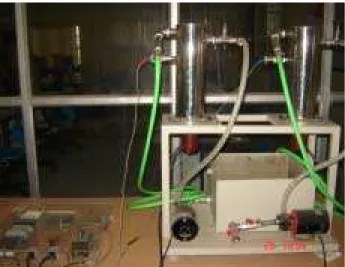
Figure 3.2 Mechanical setup of the TMCNRS
The Embedded application that runs within the Micro Controller has the following tasks:
1. Read Key Board input 2. Validate the Password
3. Read Reference Temperatures from the HOST 4. Write Initialization output to LCD
5. Write actual outputs to LCD 6. Read the sensed Temperatures 7. Compare the Temperatures 8. Actuate the buzzer
9. Set and reset the relays to control the pumps
10. Communicate with HOST to transmit the sensed Temperatures
IV. REQUIREMENTS OF CODE GENERATION FRAMEWORK FOR
GENERATING EMBEDDED SOFTWARE
The following are the requirements that must be addressed for designing the framework for Embedded Software related code generation.
1. Identification and maintaining the standard code segments dully identifying the variables used as Global, instance, return, local or arguments to the functions. A convention to refer to the kind of variables and include elements must be designed and used. The code segments may also refer to some standard functions.
2. Identification and maintaining standard functions constructed out of the standard code segments and other functions. The variables to be used in the functions must be projected as Global, Local, instance, return or functional out of the definitions included in the code segments
3. Mapping the standard functions as non member functions and defining them as friend functions within the classes where the functions are required
4. Mapping the member functions to the respective classes. While doing so define the variables as Instance or local and the global variables be declared right in the beginning of the program file 5. Recognize every software state in the state
diagram and include the methods of the classes as the entry procedures. The methods should be executed whenever a transition is made to a software state due to occurrence of either an internal or external event.
6. Generate the code
a. Include all the Global variables in the beginning of the program file
b. Include all the classes as defined in the class diagrams duly including instance variables, methods, local variables and the code
c. Develop a non member main method by tracing all the logical paths in the state diagrams and include code that facilitates the execution of the logical paths. The higher level state diagram shall be used for scheduling the tasks that are repetitive in Nature (Self loop states) and the lower level state diagrams are used for code control within the main method. Initiate the RTOS and include the RTOS functions that schedules the tasks and start the RTOS for commencement of the execution of the embedded application
d. Include all the non member functions which are declared as friends within the classes.
V. CODE GENERATION FRAMEWORK FOR EMBEDDED SOFTWARE
MODELING
CRSE has advocated that the code be developed using the state box specification. Procedures are to be executed when a system enters into a state or leaves the state or while in the state. Entering into a state happens when state transition takes place. Since every state is a snapshot of an object of a class, the procedures are the functions that are encapsulated into the classes. Code generation therefore implies that the code related to the functions be developed either manually or by some automated means. Manually coding is always erroneous and it is important that the code be generated automatically so that high quality reliable code can be obtained. Code generation is one of the essential requirements of the Embedded Systems.
It has been recommended that generation of code for the embedded system in a very structured manner and using a particular architecture will lead to delivery of high quality Embedded Systems. One of the design principles of Embedded System is that the code be developed using a standard and structured methods based on the foundations of the Frameworks.
It has been recognized that it is possible to determine standard code structures related to embedded systems. The standard code segments use global or local input and produces output again either local or Global. The standard code segments are in different files and can be included wherever necessary. The standard code segments can be stored as library and the library can be grown every time a new code segments suiting to the embedded systems are identified, the same can be included into the library. Even clean room software engineering also advocated that standard control structures be used for delivering high quality code.
The standard code functions can be identified by way of including the standard code structures and other standard code functions. Even a standard code structure can also include a standard code function. The code structures and the functions are included in the sequence such that standard logic is implemented. The standard code functions are then mapped to the classes based on the expected responsibilities of the classes. The main control logic is implemented by way of taking the instances of the classes and calling for the functions through object references.
The sequence in which the code contained in various classes gets executed based on the sequence flows that are built into the sate Diagrams. Thus the state diagrams and class diagrams used for modeling the internal behavior of the embedded systems will be the foundations using which code generation Framework can be defined and used for generating the code related to any of the embedded systems.
The code generation method proposed in this paper is primarily based on the library management which helps in reusing the library elements to construct code segments, code functions and functional modules. The framework for code generation involves several steps. A code function is a whole unit of execution generally involving one or more number of code segments. A set of code segments together with some other functions form a code function. The function units that are related to communicating with the hardware devices and the code functions units that are used as non member functions are recognized and identified as the code functions. The code functions are either general purpose functions such as converting ASCII to HEX or specific member functions that processes and communicate
with a peripheral device. The code functions will be defined with various types of variables based on the code segments included in them. Some more variables that are specific to the code functions are defined within the code functions. Every code segment will clearly recognize variables, their types and location where the variables must have been declared including the details of locations which include, Global, instance, local, functional arguments and return variables. This way of categorizing the variables will clearly help in mapping and constructing code functions and the class modules in which the code segments are placed.
The code segments are pre identified and developed as a library over a period of time. The library is maintained and more number of code segments are added to the library as when needed especially when a ES application is analyzed and designed. The code segments identified in respect of TMCNRS are placed in a library of Code Segments. A code segment may include many other code segments or may even call code functions.
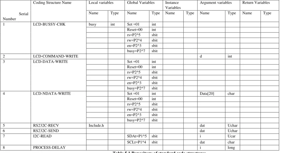
A repository of code segments can be maintained which will be used latter for resolving and placing the variables in appropriate locations. The details of the repository constructed for locating and maintaining the standard code structures that help generating the code for TMCNRS is shown in the Table 5.1. The Framework is implemented through several steps of execution
Step #1 Construct a Library of the code segments
A code segment is a unit of execution that is required quite frequently. The code units that are related to communicating with the hardware devices and the code units that are used in non member functions are recognized and identified as the code segments. Every code segment will clearly recognize variables, their types and location where the variables must have been declared including the details of locations which include, Global, instance, local, functional arguments and return variables. This way of categorizing the variables will clearly help in mapping and constructing code functions and the class modules in which the code segments are placed.
The code segments are pre identified and developed as a library over a period of time. The library is maintained and more number of code segments is added to the library as when needed especially when a ES application is analyzed and designed. The code segments identified in respect of TMCNRS are placed in a library of Code Segments. A code segment may include many other code segments or may even call code functions.
appropriate locations. The details of the repository constructed for locating and maintaining the standard code structures that help generating the code for TMCNRS is shown in the Table 5.1. The contents of the Code Segments Library designed for TMCNRS systems are placed below:
Step #2 Construct a Library of Non-member functions
Code functions may be member functions or member functions. The functions that are mapped to the classes shall be the member functions and the remaining functions shall be non member functions but shall be declared as friend functions with the classes wherever needed. When non member functions are mapped to the classes the same will be defined as non member functions.
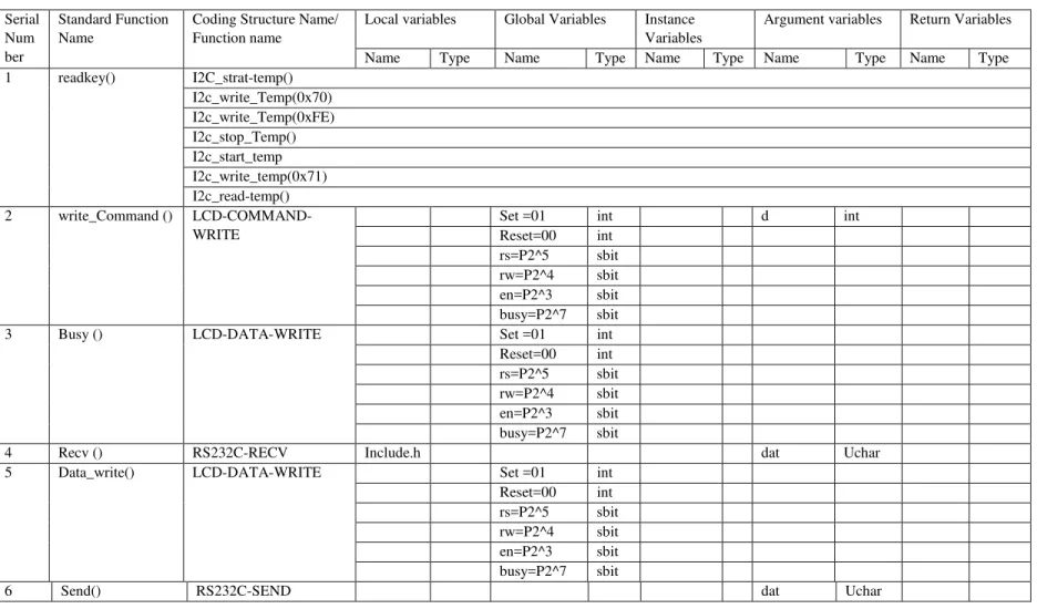
A library of standard non member functions are identified and maintained as shown in the Table 5.2. The Mapping of the code segments to the Non Member functions is also shown in the Table 5.2. When code segments are included into a function, the variable declarations as instance, global local, and return or functional shall be automatically got projected and maintained.
Step #3 Construct a Library of Hardware related Code functions
Some of the Code functions are member functions of the classes that are related to Hardware Devices. A library of standard member functions that are related to hardware are identified and maintained as shown in the Table 5.3. The Mapping of the code segments to the Member functions of the Hardware classes is also shown in the table 5.3. When code segments are included into a function, the variable declarations as instance, global local, and return or functional shall be automatically get projected and maintained.
Step #4 Map the Non member functions to the Classes
The non member functions are mapped to various classes as friend functions as necessary. The mapping of the Non member functions to the classes has been shown in the
Table 5.4. When non member functions are mapped to the classes the Global variables and instant variables will be located at global declarations or instance declarations as the case may be. When functions are mapped, the variable declarations shown in the function definition will be automatically located either as Global or instance variables
Step #5 Map the Hardware dependent functions to the classes that are related to the Hardware
The hardware dependent functions are mapped to the classes that implement the interface with the hardware devices. The data repository showing the mapping is shown
in the Table 5.5. The following are the classes related to Hardware. When functions are mapped, the variable declarations shown in the function definition will be automatically located either as Global or instance variables
Step #6 Map the Hardware dependent variables to the classes that are related to the Hardware
Some of the classes that are related to the Hardware just have variables that are defined to map to the PINS and ports of the Micro controller to which the hardware devices are connected. Signals are asserted on the PINS of the micro controller by way of setting the memory variables with appropriate values. Data variables which are mapped to the PINS are inserted to the classes based on the Connectivity details.
Step #7 Maps the Support oriented functions to the supporting Classes
Some of the functions are supporting functions that are necessary for undertaking specialized activities. Such functions are mapped to the classes that provide supporting services to other classes. The mapping of supporting functions to the supporting classes is shown at the Table
5.6. When supporting functions are mapped, the variable declarations shown in the function definition will be automatically located either as Global or instance variables
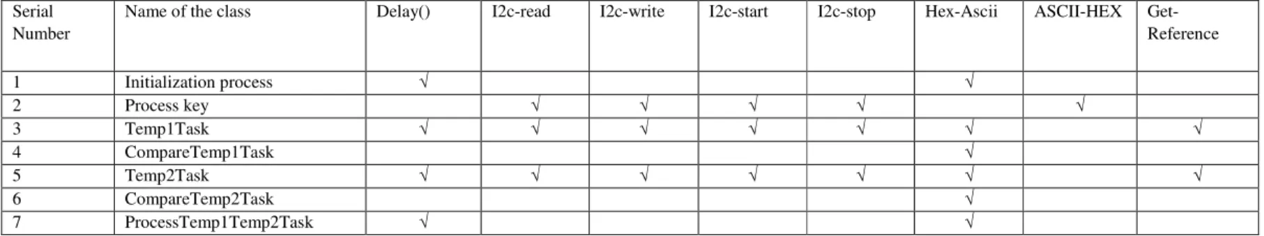
Step #8 Maps Task oriented functions to the classes that are self looped
Some of the functions are Task oriented functions that are necessary for undertaking Task oriented activities. Such functions are mapped to the classes that provide Task execution services to other classes. The mapping of task oriented functions to the Task oriented classes is shown at the Table 5.7. When task oriented functions are mapped, the variable declarations shown in the function definition will be automatically located either as Global or instance variables
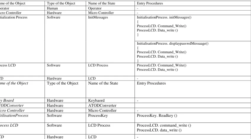
Step #9 Maps the class functions as the entry procedures of system states.
objects and each of the objects be in different states and execute procedures when the system enters into a particular state. Table 5.8 shows various objects and states into which the objects undergo transitions and the kind of procedures executed for realizing a user requirement.
Step #10 Generate Main Control of execution
The following procedure helps building the main function in which central control logic is situated.
1. Consider the Top Level State diagram shown at the figure at Figure 5.1.
2. The procedures that are mapped to the super states which are self looping states shall be recognized as the task that must be scheduled within the real time operating system.
3. Crate a buffer of such schedulable tasks. For each of the tasks crate a stack as character arrays of a default length 3000 Bytes
4. For each of the Non schedulable super state, find sub state chart as shown in the Figure 5.2. 5. Find all the State flows in sub-state chart by
following Right to left and top to bottom rule 6. For each of the sub state flow find all the entry
procedures and include them in the main function. 7. If any of the sub state is self looping in nature,
include infinite while loop and enclose the code within the scope of the while loop or create a finite looping through a for statement or while statement using the finiteness as the controlling parameter. 8. If a class is associated with the function/
procedure to be executed as a part of entry procedure for the first time, an instance of the class is included before the method is called 9. Include code to start the operating system
10. Consider each of the self looping super states and for each of the self looping super state, create objects that are related the entry procedures of the self looping super state
11. Include an RTOS statement for creating a task representing the entry procedure of self looping super state, under the control of RTOS including the reference to stack buffer that is created earlier 12. Include statements to start RTOS
Step #11 Generate Total codes
The generation of total code thus involves the following steps
1. Construct Library of standard code segments duly identifying the various types of variables
2. Construct library of the standard Non member functions through code segments and while doing so, consolidate types of variables especially the
global and instance variable. The local, return and functional variables are absorbed within the functions
3. Construct library of the standard Hardware related functions through code segments and while doing so consolidate types of variables especially the global and instance variable. The local, return and functional variables are absorbed within the functions
4. Create hardware dependent variable in the classes related to Hardware devices duly mapping the PINS of micro controller to the memory address variables
5. Construct library of the standard Member functions through code segments and while doing so consolidate types of variables especially the global and instance variable. The local, return and functional variables are absorbed within the functions
Figure 5. 1 Top Level State Diagrams
6. Map the Non member functions to the respective classes
7. Map hardware dependent functions to hardware processing classes
8. Map support functions to the support classes 9. Map the task oriented function to task oriented
classes
10. Include into entry procedures of each state the functions related to various types of classes.
Initialisation and Main Control
Temp-1 Process Temp-2 Process
Compare Temp1 and Temp2 Process
Reset
11. Build a main method by tracing the super state sub state charts.
Figure 5.2 Elementary level State Diagram for the Top Level State: Initialization
VI.REFINED CRSEMETHODOLOGY
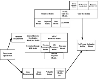
In the Figure 1.1, the refined CRSE methodology as a consequence of implementing formalism and automation for modeling the internal behavior of the embedded system has been presented. Further refinement of CRSE has been presented as shown in the Figure 6.1. The refinements are made by way of introducing the code Generation and performance optimization models. The Refined CRSE model fully satisfies the requirements of development of Embedded Systems.
VI. CONCLUSIONS
Hardware software co design requires that state models be built considering both the hardware and software states of the embedded systems. Code has to be generated using the state models. Hardware states are the instances of the classes that relate to the HW devices. Code related to ES software can be generated using Framework presented in this paper. The code generation models primarily are developed on the premises that defect free software can be developed using the standard code structures and the standard code functions built from the code segments. A repository of such standard code functions can be maintained after thoroughly testing the same. The code generation processes help is generating the high quality
software. The effort for developing code segments and code function library is one time, the segments and the function modules can be used several times whenever newer applications are to be developed.
The models presented in these chapters formalize and automate the process of modeling the clear boxes primarily through code generation
Fig 6.1 Refined Clean Room software Engineering Model after CB Stage
REFERENCES
[1] Chandra Prakash, Dr Sastry, JKR, D Bala Krishna Kamesh, “On Verification and Validation of State based Internal Behavioral Models of Embedded Systems”, International Journal of Communication Engineering Applications-IJCEA, Vol 02, Issue 02; June 2011. 73-85
[2] Chandra Prakash, Dr Sastry, JKR, D Bala Krishna Kamesh, Internal Behavioral Modeling of Embedded Systems through State Box Structures, Int. J. Advanced Networking and Applications , Volume: 02, Issue: 06, Pages: 887-899 (2011)
[3] Dr. Sastry JKR Chandra Prakash, D, Balakrishna kamesh, “Code Generation for Hardware Modeling through Clear Box Structures”, Paper communicated for publication in the forth coming issue of International Journal of Communication Engineering Application
[4] Dionision de Niz, Raj Rajkumar, “Glue Code generation: Closing the Loop Hole in Model Based Development”, IEEE Real-Time and Embedded Technology and Application Symposium (RTAS2004) [5] Gang Zhou, Man-Kit Leung and Edward A. Lee, “A
Code Generation Framework for Actor-Oriented Init
Messages
Process Key
Validate Password
Read Reference1
Process Host
LCD Process
LCD
HOST
Invalid Passwd Mesg
M1 M2
key value KeyBaord
Reset Micro Controlle ATODConverter
Init reference
Read Reference 2
Models with Partial Evaluation”, ICESS2007, 2007, Springer-Verlag Berlin Heidelberg, 786-799
[6] W. Thies, M. Karczmarek, and S. Amarasinghe, StreamIt, “A Language for Streaming Applications”, Proceedings of the 2002 International Conference on Compiler Construction, 2002, 2002 "Springer-Verlag LNCS, Grenoble, France
[7] http://www.mathworks.com/product/simulink
[8] E. Kohler, R. Morris, and B. Chen, “Programming language optimizations for modular router configurations”, Proceedings of the Architectural Support for Programming Languages and Operating Systems (ASPLOS, 2002October, 251-263
[9] N. D. Jones, C. K. Gomard, and P. Sestoft, "Partial Evaluation and Automatic Program Generation Prentice-Hall, 1993 June
[10] Chen Xi Lu Jian Hua Zhou ZuCheng and Shang YaoHui, “Modeling SystemC Design in UML and Automatic Code Generation”, ASP-DAC 2005 [11] Felix Lindlar and Armin Zimmermann, “A code generation tool for embedded automotive systems based on finite state machines”, IEEE international Conference on Industrial Informatics (INDIN 2008) Korea2008, July 13-16
[12] Matteo Bordin and Tullio Vardanega, “Real- Time Java from an automated code generation perspective", JTRES'07, Vienna, Austria" 2007 Sept, 26-88 [13]Marko Hannikainen,Jarno Knuutila, Antti Takko, Timo
Hamalainen and Jukka Saarinen, “Automatic C-Code generation from SDL for a wireless MAC PROTOCOL”, IEEE International Symposium on Intelligent Signal Processing and Communication System (ISPACS 2000) Honolulu, Vol. 1 PP 533-538, 2000
[14] Kjeld H. Mortensen,”Automatic Code Generation from Colored Petri Nets for an Access Control System”, Proceedings of 2nd workshop on practical use of Colored Petri nets and Design / CPN 1999 [15] Kathy Dang Nguyen, Zhenxin Sun, P.S. Thiagarajan
and Weng -Fai Wong, “Model-driven SoC Design via Executable UML to SystemC, Real-Time Systems Symposium, 2004. Proceedings 25th IEEE International, 2004, 5-8 Dec.459-468
[16] Luis Gomes and Aniko Costa, “From Use cases to system implementation: State chart Based Co-Design”, proceedings of the first ACM and IEEE International Conference on Formal Methods and Models for Co-Design (MEMOCODE '03)2003
Biographies
Dr JKR Sastry is presently working as Professor of Computer Science and Engineering at K L University, vaddeswaram and has 35 Years of experience in the field of Information Technology. Has served the IT industry for 25 years worldwide and has been serving the Educational Institutes for the last 9 years. Has published 55 papers in the fields of Embedded Systems, Data warehousing, Data Mining, Software Engineering and Wireless Communication in the International Journals and Conferences. Has been the reviewer for several IEEE sponsored International and National Conferences. Has Chaired 2 International Conferences. Has directed 4 Ph.D. programs and has been directing 8 Ph.D. programs concurrently.
Prof. V. Chandra Prakash is presently working in the department of Computer Science and Engineering at K L University, Vaddeswaram and has 35 years of experience spanning across the Industry and Educational institutes. He has so far published 16 papers in the International Journals and Conferences in the field of Software Engineering and Embedded systems.
Serial Number
Coding Structure Name Local variables Global Variables Instance
Variables
Argument variables Return Variables
Name Type Name Type Name Type Name Type Name Type
1 LCD-BUSSY-CHK busy int Set =01 int
Reset=00 int
rs=P2^5 sbit
rw=P2^4 sbit
en=P2^3 sbit
busy=P2^7 sbit
2 LCD-COMMAND-WRITE d int
3 LCD-DATA-WRITE Set =01 int
Reset=00 int
rs=P2^5 sbit
rw=P2^4 sbit
en=P2^3 sbit
busy=P2^7 sbit
4 LCD-NDATA-WRITE Set =01 int Data[20] char
Reset=00 int
rs=P2^5 sbit
rw=P2^4 sbit
en=P2^3 sbit
busy=P2^7 sbit
5 RS232C-RECV Include.h dat Uchar
6 RS232C-SEND dat Uchar
7 I2C-READ SDAt=P1^5 sbit i Ucar
SCLt=P1^4 sbit dat char
8 PROCESS-DELAY i long
Serial Number
Standard Code Function
Coding Structure Name
Local variables Global Variables Instance
Variables
Argument variables Return Variables
Name Type Name Type Name Type Name Type Name Type
1 I2C_read-Temp() I2C-READ i Char SDAt=P1^5 sbit i Ucar
dat char SCLt=P1^4 sbit dat char
2 Dealy() PROCESS-DELAY i long
3 I2C_write_Temp() I2C-WRITE i Char SDAt=P1^5 sbit i uchar
dat char SCLt=P1^4 sbit dat char
4 I2c_start-temp() I2C-START SDAt=P1^5 sbit
SCLt=P1^4 sbit
HIGH=1 Int
LOW=1 int
5 I2c_stop_Temp() I2C-STOP SDAt=P1^5 sbit
SCLt=P1^4 sbit
HIGH=1 int
LOW=1 int
6 asciiToHex() ASCII-TO-HEX Digit0 Char value char dat unsigned
Digit1 Char
Ascii0 Char
Ascii1 Char
Ref1 Int
Ref2 int
7 HexToAscii() HEX-TO-ASCII temp usgin
ed
Digit0 Char value char
Digit1 Char
value char dat usigned
Serial Num ber
Standard Function Name
Coding Structure Name/ Function name
Local variables Global Variables Instance
Variables
Argument variables Return Variables
Name Type Name Type Name Type Name Type Name Type
1 readkey() I2C_strat-temp()
I2c_write_Temp(0x70) I2c_write_Temp(0xFE) I2c_stop_Temp() I2c_start_temp I2c_write_temp(0x71) I2c_read-temp()
2 write_Command ()
LCD-COMMAND-WRITE
Set =01 int d int
Reset=00 int
rs=P2^5 sbit
rw=P2^4 sbit
en=P2^3 sbit
busy=P2^7 sbit
3 Busy () LCD-DATA-WRITE Set =01 int
Reset=00 int
rs=P2^5 sbit
rw=P2^4 sbit
en=P2^3 sbit
busy=P2^7 sbit
4 Recv () RS232C-RECV Include.h dat Uchar
5 Data_write() LCD-DATA-WRITE Set =01 int
Reset=00 int
rs=P2^5 sbit
rw=P2^4 sbit
en=P2^3 sbit
busy=P2^7 sbit
6 Send() RS232C-SEND dat Uchar
Serial Number
Name of the class Delay() I2c-read I2c-write I2c-start I2c-stop Hex-Ascii ASCII-HEX
Get-Reference
1 Initialization process √ √
2 Process key √ √ √ √ √
3 Temp1Task √ √ √ √ √ √ √
4 CompareTemp1Task √
5 Temp2Task √ √ √ √ √ √ √
6 CompareTemp2Task √
7 ProcessTemp1Temp2Task √ √
Table 5.4 Mapping Non member functions to the Classes
Serial Number
Name of the class Readkey ()
Command-write()
Data-write() Busycheck () Send() Receive()
1 ProcessKey √
2 ProcessLCD √ √ √
3 ProcessHOST √ √
Table 5.5 Mapping Member Functions to the Hardware classes
Serial Number
Name of the class ComparePasswd CompareTemp1withRef CompareTemp1withRef
1 ValidatePasswd √
2 CompareTask1 √
3 CompareTeask2 √
Table 5.6 Mapping Supporting Functions to the supporting classes
Serial Number
Name of the class displayInitMessage displayEnterpasswd Message
readRefTemp ConvertrefrenceDi gits
Temp1Processi ng Task
Temp2process Task
comapreTem p1Temp2Tas k
1 InitialisationProcess √ √ √ √
2 Temp1Task √
3 Temp2Task √
4 ProcessTemp1Temp2Task √
Name of the Sequence Name of the Object Type of the Object Name of the State Entry Procedures
Display Init Messages based on the reset button
Operator Human Operator -
Micro Controller Hardware Micro Controller -
Initialization Process Software InitMessages InitialisationProcess. initMessages()
{
ProcessLCD. Command_Write() ProcessLCD. Data_write () }
InitialisationProcess. displaypasswdMessaage() {
ProcessLCD. Command_Write() ProcessLCD. Data_write () }
Process LCD Software LCD Process ProcessLCD. Command_Write()
ProcessLCD. Data_write ()
LCD Hardware LCD -
Read password through Key strokes
Name of the Object Type of the Object Name of the State Entry Procedures
Key Board Hardware Keybaord -
ATODConverter Hardware ATODConverter
Micro Controller Hardware Micro Controller -
InitilisationProcess Software ProcessKey ProcessKey. Readkey ()
Process LCD Software LCD Process ProcessLCD. command_write () ProcessLCD. data_write ()
LCD Hardware LCD -