STEREO VISION IN BLIND NAVIGATION ASSISTANCE
F
ERNANDES,
H.
1,
C
OSTA,
P.
3,
F
ILIPE,
V.
1,
H
ADJILEONTIADIS,
L.
4,
B
ARROSO,
J.
1,2 1University of Trás-os-Montes e Alto Douro, 5001-801 Vila Real, Portugal
2Knowledge Engineering and Decision Support Research Group, ISEP, 4200-072 Porto, Portugal 3Polytechnic Institute of Leiria, Department of Informatics Engineering, Leiria, Portugal 4
Department of Electrical and Computer Engineering, Aristotle University of Thessaloniki, Greece ABSTRACT
Visual impairment and blindness caused by infectious diseases has been greatly reduced, but increasing numbers of people are at risk of age-related visual impairment. Visual information is the basis for most navigational tasks, so visually impaired individuals are at disadvantage because appropriate information about the surrounding environment is not available. With the recent advances in inclusive technology it is possible to extend the support given to people with visual impairment during their mobility. In this context we propose a system, named SmartVision, whose global objective is to give blind users the ability to move around in unfamiliar environments, whether indoor or outdoor, through a user friendly interface. This paper is focused mainly in the development of the computer vision module of the SmartVision system.
Key Words: Blind Navigation, Accessibility, Computer Vision, Hough Transform, GIS
1. INTRODUCTION
According to the World Health Organization (WHO), global trends since the early 1990s show reduced rates of visual impairment and a shift in the causes. Visual impairment and blindness caused by infectious diseases has been greatly reduced, but increasing numbers of people are at risk of age-related visual impairment as the global population grows and demographics shift to a higher proportion of older people, even in developing countries [1]. Statistically, about 314 million people are visually impaired worldwide, 14.3% of which are completely blind (45 million people).
Visual information is the basis for most navigational tasks, so visually impaired individuals are at disadvantage because appropriate information about the environment is not available [2]. Two low technology aids for blind people are commonly used: the white cane and the guide dog [3]. These two aids are sufficiently functional and have been adopted for many years. But they only give information regarding near objects or obstacles, failing to provide support for orientation/navigation and leaving the blind restricted to navigation in familiar environments. Thus comes the necessity of developing systems that support the visually impaired in having reliable information at their disposal, so they can move around without any constraints or difficulties.
With the recent advances in inclusive technology it is possible to extend the support given to people with visual impairment during their mobility. Recent research efforts are being directed to produce new navigational systems in which digital video cameras are used as vision sensors. Computer vision systems are undergoing a great development, which may allow visually impaired people to have access to better information of the surrounding environment, such as detect the presence of obstacles or points of interest and calculate how far the user is from them [4].
In this context we propose a system, named SmartVision, whose global objective is to give blind users the ability to move around in unfamiliar environments with contextual information, whether indoor or outdoor, provide geographic decision making capability based on data stored on, and fed by, a Geographic Information System (GIS), complemented by the use of a stereo vision system to help keeping the blind user on course, making the navigation/orientation safe and accurate. This system provides outputs through a user friendly interface. This paper is focused mainly in the development of the computer vision module of the SmartVision system.
This document consists of 5 sections. Section 2 presents an overview of related works within this area of research. In section 3 we describe the global architecture of the SmartVision system prototype and its different supporting technologies. Section 4 presents the computer vision system used and exposes the techniques and their implementation in the SmartVision computer vision module, as well as some tests and results. Finally, in section 5, we present conclusions about steps done so far, as well as discuss some features that can be developed as future work.
2. RELATED WORK
Some systems that use vision sensors to help blind user to get information about the surrounding environment have already been developed. In vOICe [5], the image is captured using single video camera mounted on a headgear and the captured image is scanned from left to right direction for sound generation. The top portion of the image is converted into high frequency tones and the bottom portion
into low frequency tones. The loudness of sound depends on the brightness of the pixel. Similar work has been carried out in NAVI [6]. In this system the captured image is resized to 32 X 32 and the gray scale of the image is reduced to 4 levels, representing 4 distance categories. With the help of image processing techniques, the image is differentiated into objects and background according to the 4 distance categories previously established, being that brighter pixels represent closer objects. This way objects are assigned with high intensity values and the background is suppressed to low intensity values. The processed image is then converted into stereo sound where the amplitude of the sound is directly proportional to intensity of image pixels, and the sound frequency is inversely proportional to vertical orientation of pixels.
Distance is one of the most important aspects for collision free navigation. The way human beings use two eyes to see and perceive the three-dimensional world has inspired the use of two cameras to model the world in three dimensions. The different perspectives of an object, as seen by two cameras, results in a relative displacement of the object in each view (disparity). The size and direction of these disparities can be used for depth estimation.
The use of stereo vision for blind navigation application is in early stages and only limited research efforts has been reported in it. In Optophone [7], to obtain a depth map, an edge detection routine is applied to images from two cameras. Disparity is calculated using the edge features of both the images. The depth map is then converted into sound using the method applied in the vOICe system and the loudness of sound is directly proportional to the intensity of the pixel. In Optophone the disparity map of all the edge features in the images is obtained. With only the edge information, it will be difficult to identify the object properly, since unwanted edge features will also exist.
Another important work reported in this area is the visual support system developed by Yoshihiro Kawai and Fumiaki Tomita [8]. The prototype system has a computer, three small cameras, an headset with a microphone, an headphone and a sound processor. The images captured by the small stereo cameras are analyzed to obtain a 3D structure representing the environment in front of the user, and object recognition is performed. The results are then converted and provided to user via 3D virtual sound. Although the information retrieved by this system is much more accurate than other systems, the prototype developed has big dimensions and it’s not portable.
The use of haptic devices to provide the system’s outputs to the user is very convenient because, usually, blind people rely very much in the hearing sense for safe navigation and environment recognition. A pioneering work by Zelek et. al., involving stereo vision systems, was designed to provide information about the environment through tactile (haptic) feedback to the blind user [9]. In this work the cameras capture the images, and the disparity is calculated from the two relative views. The depth information is provided to the user by stimulating the fingers and no image processing efforts are undertaken to highlight the object information in the output.
Although it is clear that efforts have been made to use stereo vision to help blind people in the task of navigating safely and accurately, there is still a lack of contextual information given to the user during the navigation.
3. SMARTVISION PROJECT
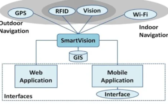
A system to assist the navigation of blind or visually impaired people is currently being developed at the University of Trás-os-Montes and Alto Douro (UTAD). This project is named SmartVision and its main objective is to develop a system that helps visually impaired people to navigate, providing ways to get to a desired location and, while doing so, giving information about obstacles and various points-of-interest (POI) like zebra-crossings, building entrances, etc. The system is built in a modular structure, combining several technologies, as seen in Figure 1.
The SmartVision Module is responsible for managing and establishing communication between all the available modules. This module also receives inputs from the user and makes decisions on what information the user should get from the system.
The Location Module is responsible for providing regular updates on the user’s current geographic coordinates to the SmartVision Module. To provide this information both in indoor and outdoor environments, this module makes use of different technologies: Global Positioning System (GPS) for outdoor environments and Wi-Fi for indoor environments. Radio-Frequency Identification (RFID) and Computer Vision are common to both indoor and outdoor environments and are based on the detection of landmarks placed in the ground. Each location technology has a specific accuracy and the Location Module always chooses the one with the best accuracy from the ones available in each moment. In terms of hardware, the RFID reader is placed in the white cane and the camera is chest-mounted. The GPS antenna is connected via Bluetooth and the Wi-Fi antenna is a built-in component of the mobile computer. The Navigation Module is responsible for route planning and providing information about surrounding points-of-interest (POI). It connects to the SmartVision Module and requests two different data inputs: GIS data and location data. To get the GIS data, the SmartVision Module queries the GIS
server in order to get maps and POIs. The user location is fed from the Location Module. After analyzing the requested data, the Navigation Module feeds back the SmartVision Module with navigation instructions. The amount and accuracy of the GIS data stored in the GIS server is critical in order to feed the blind user with the most appropriate instructions.
The Computer Vision Module provides orientation instructions by detecting known landmarks in the ground and keeping the user within safe routes. Using a stereo vision system, disparity information is extracted from the captured image frames and can be used to create a depth map. This information is useful to know the distance between the user and detected landmarks. So, in addition to giving orientation instructions to the SmartVision Module, with this distance information, the Computer Vision Module has the possibility to feed the Location Module with location information.
Finally, the Interface Module provides user interface using two outputs and one input. The two outputs are text-to-speech software and vibration actuators. Since the hearing sense is very important to blind users, the vibration actuators are used for navigation guidance and the voice interface is used for menu interaction and to provide POI information. The user gives inputs to the system by using a small four-button device to scroll between the menus, apply the options and go back to the previous menus.
Figure 1 – SmartVision’s modular structure
The user interacts directly with the SmartVision Module through the Interface Module and all other modules are independent. This way, the user can get information even when some modules are not available, or cannot provide information. For example, if GPS is not available or if the user is in an indoor environment, the Location Module can get information from the RFID tags, Wi-Fi or Computer Vision Module. Redundancy is, therefore a very important factor to increase the reliability of the system.
4. COMPUTER VISION MODULE
The image data can assume different forms, but typically stands as a 2D representation of the original 3D world. Therefore the depth information is usually lost. Some techniques have been developed to recover the depth information after image capture, namely, stereo vision, analysis of movement, shading and texture gradient.
With two cameras it is possible to generate images suitable to extract both the position and distance of objects according to their relative brightness. These images are known as depth maps. Finding a perfect disparity map is impossible in the general case because many points that appear in one image may not appear in the other for various reasons such as occlusions, reflections, or poor texture. Although this process increases the computation time, it greatly decreases the information disorder in the image as well as the chance of information overload to the user [7].
Figure 2(a) represents two images of the same area acquired simultaneously by a stereo vision system. The images look similar; however they have a small displacement. Based on that displacement, the system is capable of determining the distance of the objects present in the scene to the cameras.
(a) (b)
Figure 2 - (a) two different views of the same scene and (b) corresponding disparity map.
Distance is inversely proportional to disparity. So, as seen in Figure 2(b), pixels with higher intensity values (brighter) represent objects closer to the cameras and lower intensity values (darker) represent objects far from the cameras.
The stereo vision system used in this work is the Bumblebee 2 developed by Point Grey Research. The Bumblebee is a packaged system that includes two pre-calibrated digital progressive scan Sony ICX084 CCD cameras with a baseline (the distance between cameras) of 12cm, and a C/C++ Software Development Kit [PGR 2003], and a 400 Mbps IEEE-1394 Firewire interface for high speed communication of the digital video signal. Gain and shutter control can be set to automatic or adjustable manually. The calibration information is preloaded into the camera allowing the computer software to retrieve it for XYZ coordinate calculations and image correction.
The FlyCapture SDK was used for image capture and camera control. The image size used in this work is 512 by 384 pixels. For the calculation of the disparity and the correction of the images we used the Triclops SDK. Both this SDKs are provided together with the Bumblebee 2 stereo vision system.
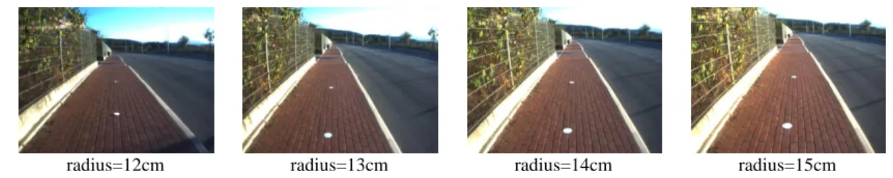
Since the main objective of this work is to provide navigation assistance to blind people, the vision system must be able to detect relevant features in the scene and help the user to keep safe courses, like street walks or zebra crossings. To achieve this, these features must have specific and constant characteristics that help the system to detect the correct path to be taken and provide corrective indications to the user in cases where he starts getting out of course. To simplify the feature detection in the captured scene we decided to use white circular markers in the ground representing safe paths that must be followed by the user. Due to the size of the captured image different radius of the circle were experimented and the chosen radius was 15cm, as seen in the last image of Figure 3.
radius=12cm radius=13cm radius=14cm radius=15cm
Figure 3 – Examples of acquired images, containing circles of different radius.
The image processing underwent the following steps: pre-processing, circle detection, calculation of the correction angle and, finally, output of correction instructions to the blind user.
4.1. Pre-processing
Since feature detection algorithms, in most cases, has several recursive and/or cyclic steps, unwanted elements in the image may cause many cause performance drawbacks. So, before applying feature detection algorithms, pre-processing is made to select a region of interest, enhancing the performance of the system and guaranteeing that the information extracted is reliable. Another measure taken to increase performance is that we don’t analyze all the pixels in the image, but only a portion of the image closer to the user. Figure 4 shows the pre-processing sequence applied to a captured image.
Figure 4 - Pre-processing applied to the captured images: crop, binarization and edge detection. The color of the circles present in the ground is white so, after capturing the images, the circles are separated from the background through binarization. This reduces the amount of irrelevant information present in the image. After this process, a Canny edge detection filter is applied. This procedure maintains the geometric information in the image, while discarding all the un-needed and redundant information.
4.2. Circle detection
Finding geometric features in images is a common task in a large number of image processing applications. Several algorithms have been developed to detect the presence of features with specific characteristics. In the case of circles, Hough Transform for circle detection (HCT) is a very robust and reliable method of achieving this goal [10].
(1)
(2)
When the angle sweeps through the full 360 degree range, the points (x, y) trace the perimeter of a circle. If an image contains many points, some of which fall on perimeters of circles, then the job of the search program is to find parameter triplets (a, b, R) to describe each circle. If the circles present in the image are of known radius R, then the search can be reduced to 2D. The problem is simplified to find the (a, b) coordinates of the centers. The locus of (a, b) points in the parameter space fall on a circle of radius R centered at (x, y). The true center point will be common to all parameter circles, and can be found with a Hough accumulation array.
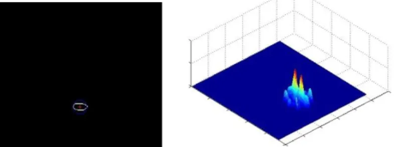
Figure 5 presents the results (detected circle and accumulation array) of the application of the HCT algorithm by the Computer Vision Module.
Figure 5 - Results of the Hough Transform for circle detection (HCT).
From the circles detected in the image, the blind user must go in the direction of the nearest circle. This ensures that he will not get out of course.
In this system, the cameras are chest mounted and, by being so, the user is not present in the image. Assuming that the user position is located in the center of the bottom line of the image and knowing the coordinates of both the user (
x
u,y
u) and the destination landmark (x
c,y
c) it is possible to calculate the correction angle ( ) that the blind user must use to correct his trajectory. This is done by simple a geometric analysis, expressed by the following equations:(3)
(4)
(5)
The first step is to calculate the slope (m value) of the straight line that connects the user to the destination landmark using equation 3. Then, from that slope value we calculate the angle of the trajectory that the user must take, as defined in equation 4. The resulting angle must be in the interval between 0 and 180 degrees. The correction angle, which represents the final indication to be given to the user, is found just by subtracting the trajectory angle from the normal vector that represents the current camera heading angle, as defined in equation 5. In the specific case of the example presented in Figure 5 the correction angle calculated is 7.5481 degrees. Safe navigation is achieved by keeping this correction value under a defined, or definable, threshold.
4.3. Output instructions
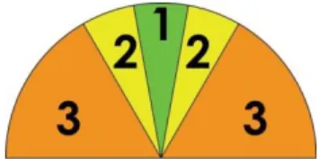
Rather than providing correction indications in absolute values, more difficult to be understood by users without sight, we chose to give the outputs according to angle intervals. Thus, for a specific correction angle value, an indication of whether this is a high or low value is given to the user. If this value is under a small threshold value, no indication is made at all. Figure 6 represents graphically the angle intervals that define the amount of correction that the user must apply. The correction indications fall under three categories, as follows:
- Zone 1 (from 0° to 10°): no correction is needed; - Zone 2 (from 11° to 30°): small correction is needed; - Zone 3 (from 31° to 90°): large correction is needed;
This is done to simplify the outputs given to the user and, at the same time, prevent information overload. An assistive system mustn’t be an obstacle itself.
Figure 6 - Correction angle intervals.
Respecting the architecture defined in the SmartVision system, represented in Figure 1, this corrective information is sent to the user via the Interface Module, specifically the haptic devices (vibration actuators).
5. CONCLUSIONS
The main objective of this work was to create a system that detects specific landmarks in the environment, provide orientation/navigation instructions and give distance information to the blind user.
With the use of circular landmarks there is no need to take into account rotation problems caused by the different viewing angles. In addition, since the area analyzed in the images is the portion closer to the user we also reduce circle deformation caused by perspective and lens distortion, while, increasing performance. With this specifications and the use of the robust Hough Transform for circle detection, the system has proven to be able to detect the defined landmarks and provide valid and simple instructions to the blind user, assisting his navigation in a non intrusive manner.
Since this is a work in progress, not all has been done yet. At the moment the disparity information (depth maps) is not being used to provide distance information together with the correction indications. Since each pixel of the depth map represents the distance of the user to the objects in the corresponding pixel of the captured image, adding the distance information to the correction outputs is a close step.
The SmartVision prototype is also composed by other modules, as seen in section 3, and, at the moment, they are all being integrated. A set of tests done to the assembled system by blind users will be performed in order to validate and improve the system.
In the future, we envisage the development of a standalone prototype to assist the navigation of blind people in the UTAD campus.
ACKNOWLEDGMENT
This research was supported by the Portuguese Foundation for Science and Technology (FCT), through the project PTDC/EIA/73633/2006 - SmartVision: active vision for the blind.
6. REFERENCES
1. World Health Organization, Webpage,
http://www.who.int/mediacentre/factsheets/fs282/en/, last visited on February 23th, 2010
2. G. Balakrishnan, G. Sainarayanan, R. Nagarajan and S. Yaacob, “Wearable Real-Time Stereo Vision for the Visually Impaired”, Engineering Letters, International Association of Engineers, 2007, pp. 6-14
3. F. Wong, R. Nagarajan, S. Yaacob and A. Chekima, “Electronic travel aids for visually impaired – A guided tour”, Proceedings of Conference in Engineering in Sarawak, 2000, pp. 377-382
4. J.D. Anderson, D.J. Lee and J.K. Archibald, “Embedded Stereo Vision System Providing Visual Guidance to the Visually Impaired”, The Third IEEE/NIH Life Science Systems and Application Workshop (LISSA), 2007, pp. 229-232
5. P. Meijer, “An Experimental System for Auditory Image Representations”, IEEE Transactions on Biomedical Engineering, 1991, pp.112-121.
6. G. Sainarayanan, “On Intelligent Image Processing Methodologies Applied to Navigation Assistance for Visually Impaired”, Ph.D. Thesis, University Malaysia Sabah, 2002.
7. M. Capp and P. Picton, “The Optophone: an electronic blind aid”, Engineering Science and Education Journal, 2000, pp. 137-143.
8. Y. Kawai and F. Tomita, “A support system for visually impaired persons to understand three-dimensional visual information using acoustic interface”, IEEE 16th conference on Pattern Recognition, 2002, pp. 974 – 977.
9. J. Zelek, S. Bromley, D. Aamar and D. Thompson, “A haptic glove as a tactile vision sensory substitution for way finding”, Journal of Visual Impairment and Blindness, 2003, pp. 621–632. 10. L. Shapiro and G. Stockman, "Computer Vision", Prentice-Hall, Inc. 2001.