A cross-system approach for multimedia
services with IP multicast in 4G networks
Diogo Gomes, Rui L. Aguiar, Susana Sargento
Instituto de Telecomunicações, University of Aveiro, Aveiro, Portugal
Abstract
The increased demand for multimedia services by mobile end users in recent years have driven both Broadcast and Wireless Network operators to develop new systems and architectures for the deployment of such services. The proposed solutions are nonetheless limited either in terms of QoS or Capabilities to deliver new interactive services. This paper highlights strengths and drawbacks of the existing technologies in terms of QoS, Security and Mobility. In order to fill the gap between current solutions we propose a new architecture that builds itself on the synergies created by a heterogeneous network made of existing delivering technologies, such as 3GPP/MBMS and DVB, where services can be delivered to end-users in the most appropriate way for end-users and operators alike. A prototype implementation is further described.
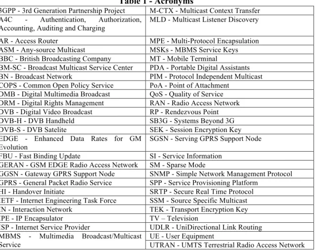
Table 1 - Acronyms
3GPP - 3rd Generation Partnership Project M-CTX - Multicast Context Transfer A4C - Authentication, Authorization,
Accounting, Auditing and Charging
MLD - Multicast Listener Discovery AR - Access Router MPE - Multi-Protocol Encapsulation ASM - Any-source Multicast MSKs - MBMS Service Keys BBC - British Broadcasting Company MT - Mobile Terminal
BM-SC - Broadcast Multicast Service Center PDA - Portable Digital Assistants BN - Broadcast Network PIM - Protocol Independent Multicast COPS - Common Open Policy Service PoA - Point of Attachment
DMB - Digital Multimedia Broadcast QoS - Quality of Service DRM - Digital Rights Management RAN - Radio Access Network DVB - Digital Video Broadcast RP - Rendezvous Point DVB-H - DVB Handheld SB3G - Systems Beyond 3G DVB-S - DVB Satelite SEK - Session Encryption Key EDGE - Enhanced Data Rates for GM
Evolution
SGSN - Serving GPRS Support Node FBU - Fast Binding Update SI - Service Information
GERAN - GSM EDGE Radio Access Network SM - Sparse Mode
GGSN - Gateway GPRS Support Node SNMP - Simple Network Management Protocol GPRS - General Packet Radio Service SPP - Service Provisioning Platform
HI - Handover Initiate SRTP - Secure Real Time Protocol IETF - Internet Engineering Task Force SSM - Source Specific Multicast IN - Interaction Network TEK - Transport Encryption Key IPE - IP Encapsulator TV – Television
ISP - Internet Service Provider UDLR - UniDirectional Link Routing MBMS - Multimedia Broadcast/Multicast
Service
UE - User Equipment
1. Introduction
The SB3G vision is tending towards a diverse wireless networking world that inherently will support any service, at any time delivered in a transparent optimized way. The demand for multimedia services delivered “anywhere and anyhow” has increased tremendously over the last few years. It is thus natural that mass entertainment markets, such as entertainment TV, become of interest for wireless operators. Such markets have always been controlled by broadcast operators, which saw in Wireless Operators a new channel for delivery of contents without jeopardizing their core business. In their view Broadcast operators would provide higher quality formats to subscribers, and Wireless operators would provide lower quality mobile contents.
This basic synergy at the content level has nonetheless been more profitable for wireless operators - that now seek to encompass the mainstream broadcast operators market into their own. Two technology trends are sustaining this. On one hand, with subscribers becoming increasingly more mobile, Broadcast Operators have developed new broadcast technologies in order to reach mobile subscribers (Such as DMB and DVB-H). On the other hand, the widespread usage of cellular networks, and the deployment of novel technologies and more powerful terminals associated to 3G networks has enabled Wireless Operators to offer higher quality contents. We have therefore a situation where operators, wireless and broadcast, may both aim to distribute quality contents like music and video, preferably to selected premium subscribers [1], and through the same type of device.
For wireless networks, a technical problem still remains: radio resource usage for broadcasting a news bulletin or a major sports event is quite expensive for the scarce radio resources. Naturally, optimizations of these resources became a major issue for wireless cellular operators: mechanisms such as 3GPP MBMS (Multimedia Broadcast/Multicast Service) [2] tried to solve this problem. Nevertheless, this approach cannot compete with the broadband solutions coming from the world of the traditional broadcast operators. Broadcast operators have long provided multimedia services for many end users in an efficient way, using radio broadcast technologies. Unfortunately these operators have large difficulties in providing interaction to end-users, and in providing services under specific customer requests.
Both types of operators, exploiting different types of media, have some competitive advantages. In a global integrated communications society, a synergy of these technologies and services for multi-user service provision is desirable, allowing a user to receive multimedia content across different technologies, regardless of his main operator. Some cross-system abstraction, allowing optimal delivery of multimedia entertainment service, any time, anywhere, any technology, is thus required.
This paper discusses an evolutionary heterogeneous scenario where cross-system design has been applied between Wireless and Broadcast Operators/Systems in order to provide better services to subscribers. The paper describes the use of IP Multicast based techniques for the efficient provisioning of multicast content in section 2, a key technology for our cross-system solution. In section 3 we analyze current cellular operator models, the 3GPP MBMS is summarized as an approach to the integration of broadcast delivery channels in the wireless infrastructure. In section 4, we present a proposal to extend the MBMS concept to any broadcast technology capable of supporting IP (such as Digital Video Broadcasting, DVB [3]), discussing aspects as security, QoS, mobility. We further present implementation details of our prototype (developed under the scope of the Daidalos project [4]) in section 5. The paper concludes with a discussion on these broadcast architectures and on possible synergies between broadcast and Telecom operators made possible by our cross-system design.
2. IP Multicast
With IP becoming a central technology for heterogeneous network integration, it is natural for IP multicast [5] to be seen as the stepping-stone for reliably providing data to several end terminals scattered around several networks. In its essence, IP multicast enables a source to transmit to several destinations using a single communication stream; the network has then the responsibility to duplicate the stream in the necessary network elements (routers) along the path, to make it reach the multiple end-users. It is also a task of the network to manage end-user changes, in terms of interest and mobility, and optimize the (variable) routes taken by the stream to reach all the end-users.
IP multicast presents obvious bandwidth advantages, since it requires fewer resources to support a large number of users, both from the point of view of the network and of the servers. Nonetheless, multicast is not as widespread as would seem obvious. Most ISP IP routers need to be upgraded to be able to support IP multicast, and given the low costs of upgrading physical networks to new technologies, and the (until now) few services able to exploit multicast, operators have steadily invested in improving their bandwidth, and not in optimizing their resources. IP multicast was then kept out of the commercial mainstream, although much development and maturing occurred in these years. It is interesting to notice that BBC[6] has since 2006 transmitted in IP multicast inside the UK in partnership with a limited number of ISP’s.
The development of IPv6 associated to mobile networking has rekindled the interest in IP multicast. IPv6 was developed from the start taking into consideration IP multicast. IPv6 multicast is supported by several fields and protocols: a 128 bits group address space, a scope identifier for domain control of the multicast group, a new version of the protocol-independent routing protocol, designated by Protocol Independent Multicast (PIM), and group membership mechanisms, designated by Multicast Listener Discovery (version 2, MLDv2[7]), which aims to enable hosts to communicate the multicast group they wish to subscribe.
Multicast routing uses PIM and its variants Sparse Mode (SM), Source Specific Multicast (SSM) and Any Source Multicast (ASM), to construct the multicast tree used to forward the multicast packets from the source to the terminals. These trees can be based in two different approaches. PIM-SM employs a special configured router, denoted by Rendezvous Point (RP), which serves as a meeting (common) point for multicast senders and listeners. Leaf routers that detect multicast listeners via MLDv2 generate join messages and send them in unicast to the RP. Multicast senders forward their packets to the RP, which places them on the shared tree for distribution to joining networks. This combination of source unicast and group multicast addresses (S,G) identifies a channel in the SSM model. Broadcast media applications are thus easily supported by the SSM model.
IPv6 multicast is now mature enough to be used as a tool for cross-system distribution of multimedia content: a mechanism for efficient content delivery to end-users, while sparing resources in the operator networks and reducing load on the content provider’s servers. These advantages of IPv6 multicast are the reasons that made interesting its usage inside the 3GPP MBMS sub-system.
3. MBMS
The Multimedia Broadcast/Multicast Service (MBMS) was initially specified in 3GPP Release 6 [8]. It is a point-to-multipoint service in which data is transmitted from a single entity to multiple recipients sharing the same radio resources, thus providing a more efficient use of resources. To support MBMS (see Figure 1) existing packet
switched domain functional entities, such as the GPRS Gateway Support Node (GGSN), Serving GPRS Support Node (SGSN), UMTS Terrestrial Radio Access Network (UTRAN), GSM EDGE Radio Access Network (GERAN), and the User Equipment (UE) need to be enhanced. Moreover, a new functional entity needs to be added to the 3G architecture: the Broadcast-Multicast Service Centre (BM-SC).
UE UTRAN SGSN GGSN BM-SC GERAN UE Uu Um Iu/Gb Iu Gn/Gp Gmb/Gi IP IP Content Provider / Multicast Broadcast Source Content Provider / Multicast Broadcast Source Figure 1 MBMS Architecture MBMS Architecture
MBMS provides delivery of IP multicast datagram’s from the Gi reference point (see Figure 1) to UEs with a specified QoS. On the control plane, it manages the MBMS bearer service activation status of the UEs, outsources authorization decisions to the BM-SC, provides control of session initiation/termination by the MBMS user service, and manages bearer resources for the distribution of MBMS data. IP plays a key point role in MBMS, being used to identify the particular instance of the bearer service (which is composed by an IP multicast address and an access point name - network identifier) and to manage all MBMS multicast services.
The BM-SC is the element in MBMS that bridges the IP and the UTRAN domains, interfacing in one side with the IP content provider and in the other with the GGSN. As such, it includes functionalities for user service provisioning and delivery, authorization and initiation of MBMS bearer services, charging and service announcements, and can further be used to schedule and deliver MBMS transmissions. On the service side, the BM-SC provides the UE with information on the MBMS user service, such as the codec’s used, the multicast service identification, addressing and timing. In all these processes, the BM-SC uses IPv6-based protocols for multicast, session description and service announcement.
The GGSN serves as the entry point of IP multicast traffic as MBMS data. Upon notification from the BM-SC, the GGSN is responsible for setting up the required radio resources for the MBMS transmission.
The UTRAN/GERAN is the responsible for efficient delivery of MBMS data to the designated MBMS service area. This includes the function of choosing the appropriate radio bearer based on the number of users within a cell.
The UE also needs to be enhanced to be able to activate and deactivate MBMS bearer services. Moreover, the UE may include features such as Digital Rights Management (DRM), security features, service announcement processing, service paging, and capabilities to cope with losses in the reception process (such as buffers and caches).
MBMS can operate in two modes: broadcast mode, where all terminals receive the information; and multicast mode, where only the terminals that subscribe to a specific service receive the information. These phases make a clean service provision concept, regardless of the specific supporting technology. Although both modes use the same resources, they differ on the subscription and management process.
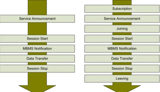
i) MBMS Broadcast Mode
Broadcast mode is its basic mode, since it does not involve subscriptions management, mostly targeting non-controlled multimedia delivery. It is composed by 5 phases: service announcement, session start, MBMS notification, data transfer and session stop. The service announcement provides the UE with information on available MBMS services, either operator specific or from the outside. The announced information includes parameters required for the service activation, such as IP multicast addresses and service start time, and content information.
Service Announcement Session Start MBMS Notification Data Transfer Session Stop Service Announcement Session Start MBMS Notification Data Transfer Session Stop Subscription Joining Leaving
Figure 2 Phases of MBMS Broadcast (left) and Multicast (right) service provision
ii) MBMS Multicast Mode
Multicast mode is similar to broadcast mode, but targeting controlled access services. Thus some higher level mechanisms for subscription management need to be considered (Figure 2). For this purpose, the multicast mode contains 3 more phases: Subscription, Joining and Leaving.
QoS Support
In the MBMS architecture, the network has the ability to control QoS parameters for sessions of multicast and broadcast MBMS bearer services. MBMS only supports two traffic classes, background and streaming. MBMS bearer services of background class are best suited for the transport of messaging or downloading services. MBMS bearer services of streaming class are best suited for the transport of multimedia streaming services, since the network here minimizes the packet transfer delay. A key difference between background and streaming classes in MBMS is the support of a guaranteed bit-rate in the streaming case. Moreover, the allocation and retention priority of the MBMS bearer service allow for prioritization between MBMS and non MBMS bearer services. When considering the whole distribution tree, the same QoS has to be made available for all its branches: it is not possible to have a new branch impacting the QoS of the
already established branches (there is no QoS value negotiation between UMTS network elements). This implies that some UEs may not be serviced if their QoS requirements cannot be accepted.
Security
Security in MBMS is achieved through a scheme of security keys. The protection is applied end-to-end between the BM-SC and the UEs, and is based on a symmetric key shared between the BM-SC and the UEs currently accessing the service. The BM-SC controls the use of the MBMS Service Keys (MSKs) to secure the different MBMS streaming/download sessions that build the MBMS user services. The MSKs are not directly used to secure the MBMS sessions: they are used to protect the delivery of MBMS Transport Keys (MTKs), which then are used to secure the MBMS sessions. MSKs and MTKs are managed at the MBMS user service level and are requested by the UE to the BM-SC by means of an authenticated HTTP procedure. The MSKs are transported in a specific message over UDP; the MTK delivery is performed over the same stream as the data.
4. A Cross-System Approach to Multimedia Delivery
MBMS is considered a large step towards integration of broadcast services into telecom operators’ networks. Nonetheless, the MBMS architecture is designed on top of a well defined access technology. The trends of next-generation architectures comprise the integration of other current broadcast technologies, such as DVB [3] and WiMax [9]. To support these technologies, operators need to rely in a homogeneous architecture able to integrate them all. A cross-system approach is thus required, providing an integrated behavior for the whole multimedia delivery, regardless of the technology being exploited at that instant. Note that if such an integrated approach is deployed, then the door is open for synergies between not only technologies but operators as well, using Federation mechanisms [11]. This will potentiate a smoother evolution path for both types of operators into the upcoming integrated communications society.Taking these aspects and requirements into account, the Daidalos project [10] addressed the delivery of multimedia services in a 4G (next generation) operator architecture capable of deploying MBMS a-like services in a heterogeneous environment, where unicast and broadcast technologies share a common provisioning platform. Our cross-system solution is then able to address this heterogeneous integration problem, both in terms of technologies and services.
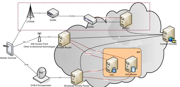
Figure 3 depicts a simplified view of the proposed 4G IPv6 operator-oriented network architecture, which includes only the entities involved in the direct support of multicast and broadcast. The legacy MBMS sub-system is clearly depicted in this figure in order to present an integrated view of the heterogeneous architecture, and also to highlight the main changes and solutions that need to be applied to cope with this heterogeneity. The heterogeneity of the access technologies imply the existence of an environment where several small operators controlling a single technology (WiFi operator, DVB-S operator, etc) are aggregated by a larger operator that controls the core network and key services, such as A4C (Authentication, Authorization, Accounting, Auditing and Charging) and end-to-end QoS. These operators will have special contracts between each other and/or federation mechanisms, enabling an integrated service delivery to the end-user. IPv6 is used as the common denominator to control all entities and to transport data over all available technologies, fully replacing the UTRAN/GERAN layers, and presenting a smooth evolution path from 3G architectures.
IP
SPP
DVB-S Encapsulator Mobile Terminal
Wifi Access Point Other bi-direcional technologies
IP IP DVB 802.11 Diameter COPS COPS Diameter IP UTRAN SGSN GGSN BM-SC Uu Iu Gn/Gp Gmb IP Gi Content Provider
Broadcast Access Router
A4C QoS Broker
Access Router
Figure 3 - 4G Network architecture including the MBMS architecture.
The core network contains a Service Provisioning Platform (SPP), composed by several enabling servers, such as the A4C and QoS Broker. The A4C server authenticates and authorizes users and services, and charges users for the accessed services. QoS Brokers manage overall network resources, providing admission control and triggering resource reservation. Mobile Terminals (MT), such as Laptops and Portable Digital Assistants (PDA), are connected to the network through the Access Routers (AR), or through the legacy UTRAN network. Each AR, connected to a different access technology, has the functionality to accept, authorize, and enforce per-flow QoS on the access links to the users. Although not clearly represented in the picture, cellular technologies are also controlled directly by an AR, in a similar way to a WiFi Access Point. Mobility requirements led to the usage of Mobile IPv6, and the inclusion of fast transfer mechanisms [18]. Furthermore, for multicast session state information, context transfer support [17] is required in the ARs.
On the access link between the MT and the AR, tight resource management is enforced by the QoS Broker, controlling the admission and policing of flows in a per-session basis, taking into account the profile of the users and network resources (this is assisted by a set of active measurements on the network). This profile is sent from the A4C to the QoS Broker on terminal registration, and has information on the set of network level services (classes of service) that may be provided to the user, essentially reflecting the user’s contract.
In this architecture, control functionalities (QoS, authentication and authorization) are distributed along the network. This allows the architecture to be free from the BM-SC control functions and the Gmb interface. These functionalities can now be assumed by the SPP and supported by IETF protocols, such as COPS (Common Open Policy Service)[13]. This distribution is very advantageous, since it avoids the requirements of an extra control plane entity (essentially removing the UTRAN/GERAN specificities), as the QoS Broker and A4C are already present in the 4G architecture for supporting unicast services [14].
To support IP multicast services, the functionalities of the routers and QoS Brokers need to be extended, compared to the ones required for the support of unicast services. The routers are in charge of all routing mechanisms involved in the establishment, maintenance and management of the multicast network, while the QoS Brokers are in charge of managing the resources associated with the use of multicast in the network.
Agents in the routers provide the necessary mechanisms for the remote control of the routing daemon by the QoS Brokers, using management protocols such as COPS or Simple Network Management Protocol (SNMP). Multicast IP routing is performed using PIM, and mobile terminals subscribe to multicast services by means of MLDv2 reports.
QoS Support and Resource Optimization
The support of QoS in the proposed 4G network follows IETF-based approaches. In the wired access and core networks, DiffServ architecture is used to support QoS, achieving scalability and performance. In the wireless link, IntServ-alike resource management is used to provide better QoS resource control in the wireless part [14]. In both cases, a QoS Broker is the element responsible for the resource reservation and management. In multicast communications with QoS support, QoS is achieved in a per group basis. Each IPv6 multicast group corresponds to a specific QoS level that has been previously negotiated with the QoS Broker, either through a resource negotiation mechanism, or by a written Service Level Agreement between content provider and network operator. QoS Brokers need to be aware of multicast routing in order to predict the paths used by the flows. The availability of the information on the user terminals capabilities and authorized services provided by the A4C enables the QoS Brokers to take decisions on the best interests of both users and operator, maximizing network resources. Extensions to the unicast mechanisms of the QoS Brokers are nevertheless required, including the maintenance of the available multicast groups and respective QoS, and the necessary procedures to unroll a multicast tree in a series of unicast point-to-point links representing each of the tree branches. This remote control of the transport path enables the effective separation of the control plane from the transport plane. This is the opposite of the MBMS solution, where these two planes are coupled in the BM-SC. Although this separation in the presented architecture might introduce some decrease in the efficiency, this solution is much more flexible, appropriate in a heterogeneous environment, where the same entities in the control plane can effectively control several access technologies. (In fact, this architecture could operate with a MBMS environment, by exploiting an adequate interface between the SPP and the BM-SC.)
The QoS Broker is then responsible for the installation of the filters in the routers, and the configuration of the packet remarking on the network edge, connecting to the content provider. With this mechanism, the content provider packets are delivered with the contracted QoS.
A further resource optimization aspect relies on the QoS Brokers. When a multimedia session starts, the QoS Broker is the responsible for deciding what kind of logical bearer will be reserved in the radio link. If this session corresponds, e.g., to a content which is popular, a broadcast radio bearer can be used. Otherwise, a unicast bearer may be the best choice in terms of radio resources. Note that our architecture allows a dynamic switching across bearer types [11].
Security
The proposed group security solution tightly follows the proposed solution for MBMS. Two keys are used, the Transport Encryption Key (TEK) and the Session Encryption Key (SEK). The first plays a similar role to the MBMS MTK, as it is used to encrypt the Secure Real Time Protocol (SRTP) stream, while the second key is used to provide per user access control to contents. The SEK is also used for charging purposes. Since the key is personal and needs to be updated periodically, it is used as a content charging mechanism.
Interactivity Channel to support broadcast-oriented technologies
The integration of broadcast networks in this architecture, relying in IP multicast, requires the simultaneous existence of an interaction network to provide bidirectional connectivity. This assumption follows the MBMS ideas, which correctly assume that there is always a unicast channel besides the broadcast one. The integration of broadcast-oriented technologies, such as DVB, is then achieved by encapsulating the particularities of these technologies under a single abstraction layer, and then considering this as yet another IP-supported technology. Under this abstraction layer concept, broadcast media can be regarded as any other technology: mobility, security and QoS can now be solved at the IP layer, as discussed above.
Our approach follows a model similar to the one described by UDLR[15], creating a return channel. However, in our approach this channel is created at the network layer. The return channel provides an upstream connection between the mobile terminal and the AR in the broadcast network where the IPE (IP Encapsulator) resides. The setup of an IP over IP tunnel introduces an interaction medium to the unidirectional broadcast channel (Figure 4).
Unicast Access
Router Over Unicast NetworkIP over IP Tunnels Broadcast Access Router
IP over Broadcast Network
Figure 4 Interactive channel set over an IP tunnel to the broadcast access router.
By creating a tunnel at the IP layer instead of layer 2 (as in UDLR), our architecture supports business scenarios where Wireless and Broadcast operators are separate entities that simply join synergies in order to provide better services to subscribers. Another important reason for the layer 3 tunnel is the requirement for mobility support across heterogeneous technologies. Since the IP tunnel constitutes a generic IP service supported by mobile IP, the terminal can move between networks in the interactive interface, while maintaining its connection in the virtual bidirectional broadcast interface with no synchronization effort.
Multicast Session Setup over DVB Network
To illustrate the behavior of our network, we describe the complete process of multicast session setup over a DVB asymmetric bearer. The MT is necessarily multimode, with at
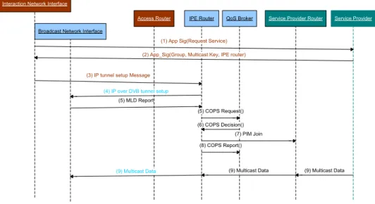
least two interfaces: one connected to the interaction network (MT IN) and another connected to the broadcast network (MT BN). In this scenario the MT requests the content provider a service that needs to be deployed over the broadcast network, either because of the nature of the service (e.g. Live TV Service) or because of service provider preferences (e.g. Stock Market Quotes). The signaling required for this scenario is schematically described in Figure 5. Note that the description below can be reinterpreted under the concepts depicted in Figure 2, showing the similarities of concepts, and supporting our evolutionary approach to the service provision problems. The MT starts by issuing a generic App_Sig Initiation message (this message can be, as an example, a HTTP GET message) to the content provider. This message contains a request for multicast service, and information on the interactive channel type and content to be received. The content provider replies back with an App_Sig Reply message (which can be a HTTP DATA), informing the MT on the availability of the service on a broadcast network. This message may also contain information on the broadcast network covering the MT and its configuration.
The MT can then contact the IPE router (AR with an attached IPE) through the interaction channel and establish an IP over IP tunnel enabling the interactive channel between both. For this purpose, the MT issues an IP tunnel Setup message to the IPE router, and upon the tunnel establishment, the IPE router answers with an IP over DVB tunnel Setup message, sent through the broadcast network. This tunnel represents a virtual interface in each of the elements forwarding the packets: the packets from the MT to the AR are sent using the IP over IP tunnel; the ones from the AR to the MT are sent using the broadcast interface. The upper services will only consider this virtual interface, and will not be aware of the complexity of the unidirectional broadcast platform. With this procedure, the broadcast infrastructure becomes completely transparent.
Interaction Network Interface
QoS Broker Service Provider Router Service Provider IPE Router
Access Router Broadcast Network Interface
(1) App Sig(Request Service)
(2) App_Sig(Group, Multicast Key, IPE router)
(3) IP tunnel setup Message
(4) IP over DVB tunnel setup
(5) MLD Report
(5) COPS Request()
(7) PIM Join (6) COPS Decision()
(8) COPS Report()
(9) Multicast Data (9) Multicast Data
(9) Multicast Data
Figure 5 - Multicast scenario over a DVB network
In such a bidirectional environment (after the tunnel establishment), the MT sends an MLD report to join a multicast tree. This request is sent through the tunnel and reaches the designated router within the broadcast network (IPE). In the broadcast network, the router sends a COPS Request message to the QoS Broker to authorize the multicast session. The QoS Broker checks the user profile (sent by the A4C) to decide if the user can have access to the requested service with its characteristics. It also checks if the available resources are sufficient to setup the required tree and to receive the service
with the requested QoS. The QoS Broker sends back a COPS Decision message with information on the service authorization. If the answer is positive, the IPE router sends a PIM Join message to the SP router, requesting the respective content. At this stage, the MT is able to properly receive the multicast stream through the unidirectional broadcast access link, with the ability to reply and interact through the IP tunnel established. This mechanism can also be extended to support IP layer service discovery mechanism, sending to the terminal the information on the broadcast network technology available and respective channels (or in alternative to exploit DVB specific information tables during a migration stage). With this information, the MT can then configure itself to attach to the new network as fast as possible, sparing time searching for the proper configurations of the broadcast interface.
Multicast Session mobility
Mobility aspects in the proposed architecture take into consideration the fact that we might be handling different types of mobility, such as: i) mobility between return channel points of attachment (POA) without change in the downlink POA; or ii) mobility of both return channel and downlink channel PoA’s. Each of these scenarios is to be handled differently as they involve different entities and services.
i) Considering the first scenario, and according to the previous section where the interactive channel was described as an IP over IP service, multicast mobility is undistinguishable from the common unicast mobility (see e.g. [19]). As the return channel is a point-to-point service over IP with the Multicast router, the return channel session is seamlessly transfered from the old POA to the new POA without any need to update any multicast context in the Multicast Router.
ii) In the second scenario, the end point of the return channel service will change, requiring the transferral of multicast subscription information to the new POA. This scenario therefore requires the definition of a mobility strategy with support for multicast services. 3GPP-MBMS provides a solution to similar problems, which we can expand for our heterogeneous context. In MBMS the existence of the “MBMS UE Context” and “MBMS Bearer Context” [2] enables the network to track terminals and bearers involved in multicast/broadcast service. A mobility event triggers the transfer of such context amongst the involved network entities (be it the SGSN’s, GGSN’s or BM-SC) enabling the proper allocation resources and provisioning of services. In 3GPP-MBMS these context transfers are done using 3GPP specific interfaces and protocols, and are therefore not appropriate for heterogeneous networks.
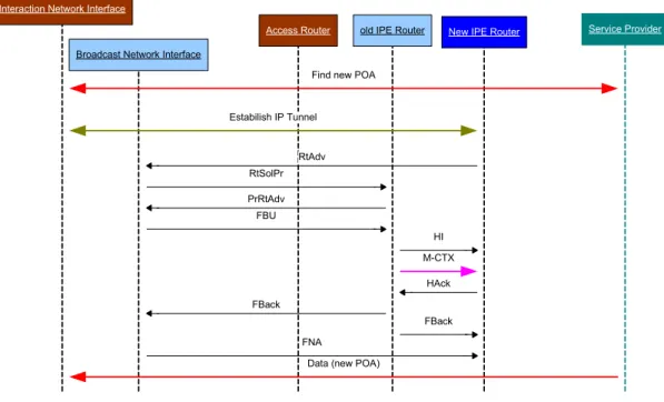
In our cross-system approach, relying in IP based interfaces and protocols, we explored the Context Transfer Protocol [17] to thus support seamless handover of any information between two nodes, therefore able to transfer the required multicast subscription information between the old POA and the new POA. This multicast context transfer re-establishes the listening and routing states for the active multicast groups and sources of the mobile node, when the node selects a new access router. Note that in our architecture, multicast group management is based on the Multicast Listener Discovery Protocol version 2 - MLDv2 [7] protocol, which creates a context in the multicast router located in the POA. Such information can then be transferred in advance from the old POA to the new POA if properly triggered by the Fast Mobile IPv6 [18], used for improving handover performance. Figure 6 summarizes such signalling scenario.
Interaction Network Interface
Service Provider New IPE Router
old IPE Router
Access Router
Broadcast Network Interface
Find new POA
RtAdv Estabilish IP Tunnel RtSolPr PrRtAdv FBU M-CTX HI FBack FBack FNA
Data (new POA)
HAck
Figure 6 - Multicast mobility via context transfer
The first message assumes that the Service Provider is responsible for informing the UE of which operators are serving the desired service, and through directory mechanisms the UE is able to find the new POA. (In the case of DVB technologies, this can be done recurring to the SI Tables which already transport this kind of information.) After discovering the new POA the UE establishes the new interaction channel while maintaining the old connection in a procedure classified as a soft-handover. Upon receiving the Fast Binding Update (FBU) and sending the Handover Initiate (HI) messages the old POA sends a Multicast Context Transfer (M-CTX) to the new POA in order for this to re-setup the multicast session. The Handover Acknowledgement (Hack) signals back the old POA that the transfer occurred successfully and that the UE can therefore start receiving the multicast stream over the new POA.
5. Implementation and Results
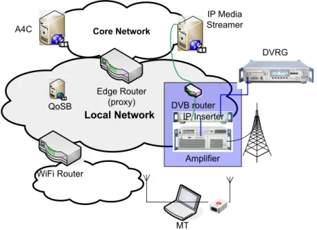
This architecture was developed and trialed in our test site in Aveiro. All functional entities were developed, including ARs, QoSB, and A4C servers [14]. Multicast routing daemons were also developed, for routing integration with the control place. A simplified representation of the testbed is presented in Figure 7.
The DVB router is in fact an AR coupled with an Encapsulator/Inserter. The functional purpose of such a device is to introduce the IP frames into the technology specific frames. DVB encapsulates IP into MPEG-2 TS (Transport Streams). The equipment which supports this feature usually is enabled with some processing capabilities. In the framework of the implementation of this architecture, an inserter was further developed to perform Multi-Protocol Encapsulation (MPE) of IP packets received from a DVB-AR, into MPEG2 transmission streams. This is performed using a specific PID filtered by the DVB network interface at the receiver. Signaling, such as router advertisements, are also encapsulated to enable the configuration of the mobile terminals. The IP inserter (Rohde & Schwarz DTV Data Inserter DIP 010) acts as a multiplexer for the IP contents provided by an IP enabled device with an Ethernet connection. The DVB Recorder and Generator (DVRG) acts like an MPEG-2 carrousel. The multiplexed
frames are then forwarded to the Amplifier (Rohde and Schwarz amplifier R&S SV8000 with enhanced firmware), which broadcasts the signal to a DVB enabled Laptop that receives it and de-encapsulates the IP frames, or simply delivers the MPEG-2 contents to the end user. The DVB signal is modulated using the Pro Television Technologies DVB-T Modulator (PT 5780) and the software runs on Linux machines (P4 2.4 MHz CPU). Local Network Core Network Edge Router (proxy) MT WiFi Router IP Inserter Amplifier DVRG IP Media Streamer QoSB DVB router A4C
Figure 7 – Partial representation of the testbed
The software for the terminals and routers was also developed on Linux (kernel version 2.6.10), as it provides good compatibility for the software used in the tests. On the mobile terminal a Technotrend TT-DVB-T USB Budget receiver was used, as well as U.S. Robotics 11 Mbps PCMCIA Cards based on Prism2 chipset. Other interfaces have also been trialed, with less success.
DVB integration performance
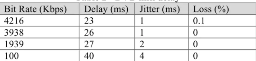
The Round Trip Time (RTT) observed with DVB and WiFi varies as the uplink channel varies according to the bandwidth. This happens due to the buffers at the DVB Inserter (used immediately after the IPE), which inserts the IP packets into the MPEG-2 TS when the stack buffer reaches a certain degree of occupation. Table 2 shows the delay for the DVB link according to the bit rate in use. This delay was obtained after synchronizing both machines: the MPE, which is providing the service, and the MN with the DVB receiver. Also, for the conditions indicated above, the maximum throughput was of 4216 Kbps.
Delay and jitter increase with the decrease of the bit rate. Their variance also increases, as the system behaves according to bursts. For a 64B/s flow, the first packets would suffer a delay up to 2 seconds, but the latest packets would have a much-reduced delay to complete the burst, as they would stay less time in the buffers of the Inserter. The following results were obtained by generating a 4Mbps traffic flow with the MGEN tool [20]. Since the AR (using wifi set to 11 Mbps) has a throughput of 5.4Mbps; the reasoning for this particular choice of bitrates is to assure the minimum delay on the Inserter, when there are still no losses in both links (DVB and WiFi).
Table 2 - DVB link delay
Bit Rate (Kbps) Delay (ms) Jitter (ms) Loss (%)
4216 23 1 0.1
3938 26 1 0
1939 27 2 0
100 40 4 0
Session setup
The session setup time of a multicast session is set around 65ms and is mostly related to the Delay of the DVB link. Results obtained [21] under the same architecture for unicast services show setup times of 25ms. The added setup time is not a problem for normal operation.
Mobility
As previously mentioned multicast mobility is undistinguishable from the common unicast mobility use case. Results presented in [19] are in accordance to the results obtained for a handover of the return channel. Due to the lack of additional DVB equipment results on the handover between IPE routers are not presented in this paper and are considered future work. Nonetheless one can predict that results should only be impacted by the delay of the DVB receiver in changing between channels.
Overall, the system performs functionally, with mobility and context transfer times on the order of some dozen milliseconds, but several details on software integration, namely driver, link abstraction and mobile IP stack issues had to be sorted out to achieve these results. In fact, the tunnel encapsulation abstraction proved to be critical to the whole process, and its integration with the mobility stack was complex in terms of software development.
6. Conclusions
This paper presented a new heterogeneous architecture capable of supporting, in the same infrastructure, unicast and broadcast technologies, including unidirectional broadcast networks, enabling the convergence of Internet and broadcast systems. Under this proposed architecture, both unicast and multicast scenarios over heterogeneous technologies are integrated. We have developed and trialed successfully such an architecture.
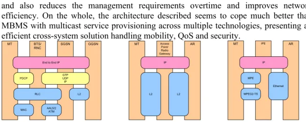
Our vision is that, in the near future, synergies between Wireless and Broadcast Operators can lead to new services and therefore new markets. Wireless and Broadcast operators are complementary and not necessarily competitors in the next generation networks market. Common service platforms for IP based network as the one described previously could potentiate synergies across services and operators, cutting cost in terms of infrastructure for Wireless Operators. Mobility will then become associated with streaming services, and interactivity – or user-dependent services – will allow for a multitude of new ways of facing traditional broadcast services, such as Mobile-TV. From the start, our 4G architecture already enables the simplification of the protocol stacks: IP is deployed directly on top of the layer 2 access technologies, as depicted in Figure 8. In this protocol stack, only the lower radio layers remain (besides IP), providing a more efficient use of the channel to transport information in both unicast and broadcast scenarios. Our 4G architecture proposal when compared with 3GPP MBMS requires less entities and layers making sole use of the 3GPP link technology instead of the overall 3GPP platform. This simplifies deployment and associated cost,
and also reduces the management requirements overtime and improves network efficiency. On the whole, the architecture described seems to cope much better than MBMS with multicast service provisioning across multiple technologies, presenting an efficient cross-system solution handling mobility, QoS and security.
MT BTS/ SGSN GGSN RNC GTP UDP IP RLC L2
MAC AAL5/2ATM
MT Access AR Point/ Radio Gateway IP L2 End to End IP PDCP L2 MT IPE AR IP MPE Ethernet MPEG2-TS
Figure 8 Comparison between 3GPP stack (left) and proposed 4G network stack (center) with its DVB realization (right), IP Datacast alike
This all-IP based architecture makes a better candidate for creating synergies between Wireless and Broadcast Operators, than any possible enhancement to already existing architectures. Their interoperation becomes simple through the usage of a common technology, with similar service provision concepts. Note that our architecture concepts are very similar to MBMS, from the point of view of the user and of the service provider, but quite different in terms of network support. Migration from current 3GPP networks to this 4G network will not be impaired by the MBMS service concepts, but only by the specific issues surrounding the UTRAN evolution into an IP-oriented technology [16].
Thus our architecture can be discussed as an evolution of the trends present in MBMS. More specifically, MBMS is one step forward on the integration of broadcast into unicast technologies, but is still missing the heterogeneous technology integration requested by 4G networks. The usage of the IP protocol brings a unifying cross-system paradigm that allows the exploitation of efficient streaming provision while supporting increased interactivity, even in broadcast-oriented technologies.
ACKNOWLEDGMENT
The work presented in this paper was partially funded by the EU project IST-2002-506997 Daidalos II, and thanks are due to several partners that contributed to its development
References
[1] Elsen, I.; Hartung, F.; Horn, U.; Kampmann, M.; Peters, L., “Streaming technology in 3G mobile communication systems”; Computer, Volume 34, Issue 9, Sept. 2001 Page(s):46 – 52
[2] 3GPP TS 23.246. Multimedia Broadcast/Multicast Service (MBMS); Architecture and functional description (Release 8)
[3] Reimers, U., Digital video broadcasting, Communications Magazine, IEEE, Volume 36, Issue 6, June 1998 Page(s):104 – 110
[4] Rui L. Aguiar, Amardeo Sarma, Dennis Bijwaard, Loris Marchetti, Piotr Pacyna, Riccardo Pascotto, “Pervasiveness in a competitive multi-operator environment: the Daidalos project”, IEEE Communications Magazine, Large Projects section, vol 45 n.10, pp 22-26, Oct 2007.
[5] Deering, S. et al, “The PIM architecture for wide-area multicast routing”, IEEE/ACM Transactions on Networking, Vol. 4, N. 2, April 1996
[6] “Multicast | TV & Radio”, http://www.bbc.co.uk/multicast/, October 2007. [7] R. Vida, L. Costa, “Multicast Listener Discovery Version 2 (MLDv2) for IPv6”,
Internet Eng. Task Force RFC3810, June 2004,
http://www.ietf.org/rfc/rfc3810.txt
[8] 3GPP TR 23.846. Multimedia Broadcast/Multicast Service (MBMS); Stage 2 (Release 6)
[9] Vaughan-Nichols, S.J., Achieving wireless broadband with WiMax, , Computer, Volume 37, Issue 6, June 2004 Page(s):10 - 13
[10] R. Aguiar, et al, “Designing Networks for the Delivery of Advanced Flexible Personal Services: the Daidalos approach“, IST Mobile & Wireless Communications Summit 2004, Lyon, France, June 2004.
[11] Diogo Gomes, Rui L. Aguiar, IP Multicast Dynnamic Mapping in Heterogeneous Environments, PIMRC 2007, 18th IEEE International Symposium on Personal, Indoor and Mobile Radio Communications, Athens, Sep 2007
[12] Chow, E. et al; “Secured Advanced Federated Environment (SAFE): a NASA solution for secure cross-organization collaboration”, WET ICE 2003. Proceedings, Juno 2003.
[13] D. Durham, Ed., et al, “The COPS (Common Open Policy Service) Protocol”, Internet Eng. Task Force, RFC 2748, January 2000; http://www.ietf.org/rfc/rfc2748.txt
[14] Susana Sargento, Diogo Gomes, Alfredo Matos, Rui L. Aguiar, “QoS Signalling in 4G Scenarios”, 15th IST Mobile Communications Summit 2006, Myconos, Jun 2006.
[15] E. Duros, et al, “A Link-Layer Tunneling Mechanism for Unidirectional Links”, Internet Eng. Task Force RFC3077, March 2001; http://www.ietf.org/rfc/rfc3077.txt Etoh, M.; Yoshimura, T., Wireless video applications in 3G and beyond, Wireless Communications, IEEE, Volume 12, Issue 4, Aug. 2005 Page(s):66 – 72.
[16] Patel, G.; Dennett, S.; “The 3GPP and 3GPP2 movements toward an all-IP mobile network”, Personal Communications, IEEE [see also IEEE Wireless Communications], Volume 7, Issue 4, Aug. 2000 Page(s):62 – 64
[17] J. Loughney, M. Nakhjiri, C. Perkins, R. Koodli: "Context Transfer Protocol (CXTP)", RFC 4067, July 2005.
[18] R. Koodli: “Fast Handovers for Mobile IPv6”, IETF RFC 4068, July 2005 [19] Justino Santos, Nuno Sénica, Susana Sargento, Rui L. Aguiar, “Mobility
Between Heterogeneous Networks: Integration and Evaluation”, The Mediterranean Journal of Computers and Networks, Special Issue on Mobile and Ubiquitous Computing, Vol. 3, No 1, 2007, pp. 31-42.
[20] MGEN, The Multi-Generator Toolset WebSite:
http://pf.itd.nrl.navy.mil/mgen/ as in Jun 2006
[21] Susana Sargento; Diogo Gomes; Alfredo Matos; Rui L. Aguiar; "QoS Signalling in 4G Scenarios 2006", Proc. IST - Mobile Summit, Myconos, Greece, Jun 2006