Universidade do Minho
Escola de Engenharia
Departamento de Eletr´onica Industrial
Ricardo Jo˜ao Rei Roriz
Enabling System Survival
Across Hypervisor Failures
Universidade do Minho
Escola de Engenharia
Departamento de Eletr´onica Industrial
Ricardo Jo˜ao Rei Roriz
Enabling System Survival
Across Hypervisor Failures
Dissertac¸˜ao de Mestrado em Engenharia Eletr´onica Industrial e Computadores
Trabalho efectuado sob a orientac¸˜ao do
Professor Doutor Sandro Pinto
Declaração do Autor
Nome: Ricardo João Rei Roriz
Correio Eletrónico: [email protected] Cartão de Cidadão: 14655239
Titulo da dissertação: Enabling System Survival Across Hypervisor Failures Ano de conclusão: 2018
Orientador: Professor Doutor Sandro Pinto
Designação do Mestrado: Ciclo de Estudos Integrados Conducentes ao Grau
de Mestre em Engenharia Eletrónica Industrial e Computadores
Área de Especialização: Sistemas Embebidos e Computadores Escola de Engenharia
Departamento de Eletrónica Industrial
De acordo com a legislação em vigor, não é permitida a reprodução de qualquer parte desta dissertação.
Universidade do Minho, 26/10/2018 Assinatura: Ricardo João Rei Roriz
Acknowledgements
This dissertation consecrates the culmination of my academic journey carried out over these six years. Thus, there are many people whom I want to thank that without their time, expertise, patience and support, I would not have completed this journey.
Firstly, I would like to thank my thesis advisor Dr. Sandro Pinto for the advices and independence, though always steering me in the right direction.
I wish to express my sincere thanks to Dr. Adriano Tavares for transforming this "pedreiro" into an embedded system engineer by sharing his knowledge. Thank you for showing me the beauty of this area.
I would also like to thank my "ESRGianos" colleagues: Ailton Lopes, Ângelo Ribeiro, Franciso Petrucci, Hugo Araújo, José Martins, José Ribeiro, José Silva, Miguel Silva, Nuno Silva, Pedro Machado and Sérgio Pereira for their feedback,
cooperation and of course friendship. I also take this opportunity to express
gratitude to all my friends, for their help and support.
Finally, I must express my very profound thankfulness to my mom, dad, sis-ter, and my beloved Ariana Bezerra for providing me with unfailing support and continuous encouragement throughout my years of study, researching and writing this thesis. This accomplishment would not have been possible without your love. Thank you.
Abstract
Embedded system’s evolution is notorious and due to the complexity growth, these systems possess more general purpose behaviour instead of its original sin-gle purpose features. Naturally, virtualization started to impact this matter. This technology decreases the hardware costs since it allows to run several software components on the same hardware. Although virtualization begun as a pure soft-ware layer, many companies started to provide hardsoft-ware solutions to assist it.
Despite ARM TrustZone technology being a security extension, many devel-opers realized that it was possible to use this extension to support development of hypervisors. With TrustZone, hypervisors can ensure one of the most impor-tant features in virtualization: isolation between guests. However, this hardware technology revealed some vulnerabilities and since the whole system is TrustZone dependent, the virtualization can be compromised.
To address this problem, this thesis proposes an hybrid software/hardware mechanism to handle failures of TrustZone-based hypervisors. By using the pro-cessor’s abort exceptions and hash keys, this project detects system malfunctions caused by imperfect designs or even deliberate attacks. Additionally, it provides a restoration model by checkpoints which allows a system recovery without major throwbacks. The implemented solution was deployed on TrustZone-based LTZVi-sor, an open-source and in-house hyperviLTZVi-sor, and the revealed results are appeal-ing. With a 6.5% memory footprint increase and in the worst case scenario, an increment of 23% in context switching time, it is possible to detect secure memory invasions and recover the system. Despite of the hypervisor memory footprint increment and latency addition, the reliability and availability that the system bring to the LTZVisor are unquestionable.
Resumo
A evolução dos sistemas embebidos é notória e, devido ao aumento da sua com-plexidade, estes sistemas cada vez mais possuem um comportamento de propósito geral, em vez das suas características originais de propósito único. Naturalmente, a virtualização começou a ter impacto sobre este meio, uma vez que permite execu-tar vários componentes de software no mesmo hardware, diminuindo os custos de hardware. Embora a virtualização tenha começado como uma camada de software pura, muitas empresas começaram a fornecer soluções de hardware para auxiliá-lo. Apesar da TrustZone ter sido projetada pela ARM para ser uma extensão de segurança, muitos desenvolvedores perceberam que era possível usá-la para suporte ao desenvolvimento de hipervisores. Com a TrustZone, os hipervisores podem garantir uma das premissas mais importantes da virtualização: isolamento entre hóspedes. No entanto, esta tecnologia de hardware revelou algumas vulner-abilidades e, sendo todo o sistema dependente da TrustZone, a virtualização pode ficar comprometida.
Para solucionar o problema, esta tese propõe um mecanismo híbrido de soft-ware/hardware para lidar com as falhas em hipervisores baseados em TrustZone. Usando as excepções do processador e chaves de hash, este projecto detecta defeitos no sistema causados por imperfeições no design e também ataques intencionais. Além disso, este fornece um modelo de restauração por pontos de verificação, permitindo uma recuperação do sistema sem grandes retrocessos. A solução foi implementada no LTZVisor, um hipervisor em código aberto e desenvolvido no ESRG, sendo que os resultados revelados são satisfatórios. Com um aumento de 6,5% da memória usada e um incremento, no pior caso, de 23% no tempo de troca de contexto, é possível detectar invasões de memória segura e recuperar o sistema. Apesar do incremento de memória do hypervisor e da adição de latên-cia, a confiabilidade e a disponibilidade que o sistema oferece ao LTZVisor são inquestionáveis.
Contents
List of Figures xviii
List of Tables xix
List of Listings xxi
Glossary xxiii
1 Introduction 1
1.1 Motivation . . . 2
1.2 Goals . . . 3
1.3 Document Structure . . . 4
2 Background, Context and State of the Art 7 2.1 Virtualization . . . 7
2.2 ARM Architecture . . . 9
2.2.1 ARM TrustZone . . . 10
2.2.2 Exceptions in ARMv7 with TrustZone . . . 12
2.3 Hypervisors Implementations . . . 15 2.3.1 LTZVisor . . . 15 2.3.2 Jailhouse . . . 16 2.3.3 SafeG . . . 17 2.3.4 VOSYSmonitor . . . 18 2.3.5 Discussion . . . 19 2.4 Exception Handling . . . 19
2.4.1 Exception Handling Implementations . . . 20
2.5 Fault tolerance concepts and Health-monitor . . . 21
2.5.1 Basic techniques in error handling . . . 22
2.5.2 Hypervisor’s Health-monitors and Recovery mechanisms . . 23
2.6 Non-Encrypted Hash functions and Checksums . . . 24
2.6.1 FNV-1 and FNV-1a . . . 25 2.6.2 SDBM . . . 26 2.6.3 DJB2 . . . 27 2.6.4 Murmur . . . 27 2.6.5 CRC32 Checksum . . . 29 2.6.6 Discussion . . . 30
3 Platforms and Tools 31 3.1 ZYBO Zynq-7000 SoC . . . 31
3.1.1 Zynq-7000 family . . . 31
3.1.2 AMBA Advanced eXtensible Interface . . . 33
3.1.3 AXI Direct Memory Access . . . 36
3.1.4 TrustZone Architecture on the Xilinx Zynq-7000 . . . 37
3.2 LTZVisor . . . 39
3.2.1 Virtual CPU . . . 39
3.2.2 Scheduler . . . 40
3.2.3 Memory Partition . . . 40
3.2.4 MMU and Cache Management . . . 41
3.2.5 Device Partition . . . 41 3.2.6 Interrupt Management . . . 42 3.2.7 Time Management . . . 43 3.2.8 Exception Model . . . 43 4 Implementation 45 4.1 Exception Handling . . . 45
4.1.1 Secure Supervisor Data abort and Prefetch abort exceptions 46 4.1.2 Monitor Data abort and Prefetch abort exceptions . . . 49
4.2 Health-Monitor . . . 51
4.2.1 Detection Module . . . 52
4.2.2 Memory module . . . 53
4.2.3 Checkpoint Module . . . 55
4.2.4 Health-monitor Mechanism Controller . . . 58
4.3 LTZVisor Integration and Health-monitor interface . . . 60
4.4 Intruder Module . . . 63
5 Evaluation and results 65 5.1 Memory footprint . . . 65
5.2 Context switching performance . . . 66
5.3 Hashes and CRCs Evaluation tests . . . 67 5.4 Hardware Costs . . . 69 5.5 Case study . . . 70 5.5.1 Exception Handling . . . 70 5.5.2 Health-monitor . . . 74 6 Conclusion 79 6.1 Future work . . . 80 References 83 xv
List of Figures
1.1 Motivational execution flow. . . 3
2.1 Hypervisor types. . . 9
2.2 ARM-v7 with Security Extensions Exception Model . . . 12
2.3 LTZVisor General Architecture . . . 15
2.4 Jailhouse hypervisor Overview . . . 17
2.5 SafeG scheduler. . . 18
2.6 SafeG hypervisor Exception Handling Overview . . . 21
2.7 FNV-1a and FNV-1 algorithms flowchart. . . 25
2.8 SDBM algorithm flowchart . . . 26
2.9 DJB2 algorithm flowchart. . . 27
2.10 Murmur algorithm flowchart. . . 28
2.11 CRC32 and respective lookup table flowcharts algorithms. . . 29
3.1 Zynq-7000 SoC overview [XI18a]. . . 32
3.2 AXI communication overview. . . 33
3.3 VALID/READY handshake. . . 33
3.4 Typical AXI DMA system configuration. . . 37
3.5 Memory partition in Zybo platform. . . 41
3.6 Interruption model in LTZVisor. . . 42
3.7 LTZVisor Exception Model. . . 44
4.1 LTZVisor Exception Handling Overview. . . 46
4.2 Fault Status register masked bits. . . 47
4.3 SPSR register masked bits. . . 48
4.4 Handler decider flowchart. . . 49
4.5 Non secure guest Execution flow. . . 51
4.6 Health-Monitor Overview. . . 51
4.7 Detection module overview. . . 52
4.8 Memory module overview. . . 54
4.9 Memory module sequence diagram. . . 55
4.10 Checkpoint module overview. . . 56
4.11 RAM swap. . . 57
4.12 Control Unit State Machine . . . 59
4.13 Control Unit actions and states overview. . . 60
4.14 Intruder Module Overview . . . 64
5.1 Algorithms Box-and-Whisker Plot. . . 68
5.2 LTZVisor Hypervisor Data Abort output. . . 71
5.3 LTZVisor Secure Guest Data Abort output. . . 72
5.4 LTZVisor Secure Guest External Data Abort output. . . 73
5.5 LTZVisor Non-Secure Guest External Data Abort output. . . 74
5.6 LTZVisor without Health-monitor output. . . 75
5.7 LTZVisor with Health-monitor output. . . 76
5.8 Health-monitor information output. . . 76
List of Tables
2.1 Fault Status encoding table . . . 13
2.2 Suggested values for FNV constants . . . 26
3.1 AXI-Lite Address Write Channel Signals. . . 34
3.2 AXI-Lite Address Read Channel Signals. . . 34
3.3 AXI-Lite Data Write Channel Signals. . . 35
3.4 AXI-Lite Data Read Channel Signals. . . 35
3.5 AXI-Lite Write Response Channel Signals. . . 35
3.6 AXI-Stream Signals. . . 36
4.1 SPSR.M bit value interpretation. . . 48
5.1 Memory footprint (bytes). . . 66
5.2 Performance values: Switching from SGuest to NSGuest. . . 67
5.3 Performance values: Switching from NSGuest to SGuest. . . 67
5.4 Algorithms evaluation result. . . 68
5.5 Resource utilization. . . 70
List of Listings
4.1 Exception handle instructions to get the FSR and FAR registers. . . 47
4.2 Exception handle instructions to get the SPSR and NS bit. . . 48
4.3 Hypervisor Linker script with the new non-secure monitor section. . 50
4.4 Code to stop the non-secure guest execution. . . 50
4.5 Health-monitor trigger code. . . 61
4.6 Health-monitor error checker. . . 61
4.7 Healthmonitor Configuration APIs. . . 62
4.8 Healthmonitor Informative APIs. . . 63
Glossary
ACTLR Auxiliary Control Register
AMP Asymmetric Multiprocessing
APB Advanced Peripheral Bus
API Application Programming Interface
AXI Advanced eXtensible Interface
BRAM Block RAM
CFI Control Flow Integrity
CPSR Current Program Status Register
CRC Cyclic Redundancy Checks
DFAR Data Fault Address Register
DFI Data Flow Integrity
DFSR Data Fault Status Register
DJB2 DJB2 algorithm
DMA Direct Memory Access
DRAM Dynamic Random-Access Memory
ESRG Embedded Sistem R
ExT External bit
FF Flip-Flop
FIQ Fast Interrupt Request
FNV Fowler–Noll–Vo
FPGA Field-Programmable Gate Array
FS Fault status bits
GIC Generic Interrupt Controller
GP General Purpose
GPOS General Purpose Operating System
IDE Integrated Development Environment
IFAR Instruction Fault Address Register
IFSR Instruction Fault Status Register
IoT Internet of Things
IP Intelectual Proprety
IRQ Interrupt Request
ISR The Interrupt Status Register
LCG Linear Congruential Generator
LPAE Large Physical Address Extension
LR Link Register
LTZVisor Lightweight TrustZone-assisted hypervisor
LUT Look Up Table
MMU Memory Management Unit
MVBAR Monitor Vector Base Address Register
NS Non Secure
NSACR Non-secure Access Control Register
OS Operative System
OSs Operative Systems
PC Program Counter
PL Programmable Logic
PMU Performance Monitoring Unit
PS Processing System
QSPI Quad Serial Peripheral Interface
RAM Random Access memory
ROM Read Only Memory
RTOS Real Time Operating System
SCR Secure Configuration Register
SCTLR System Control Register
SDBM SDBM database library
SDER Secure Debug Enable Register
SDIO Secure Digital Input/Output interface
SDK Software Development Kit
SE Security Extensions
SMC Secure Monitor Call
SoC System-on-Chip
SP Stack Pointer
SPSR Saved Program Status Register
SRAM Static Random Access Memory
TTBR Translation Table Base Register
TZASC TrustZone Address Space Controller
TZMA TrustZone Memory Adopter
TZPC TrustZone Protection Controller
VBAR Vector Base Address Register
VE Virtualization Extensions
VM Virtual Machine
VMCB Virtual Machine Control Block
VMs Virtual Machines
VT Virtualization Technology
XSDK Xilinx Software Design Kit
1. Introduction
The accentuated growth of the industry has been forcing embedded systems towards more complex solutions. Nowadays, there is a wide range of embedded sys-tems applications and domains, from basic consumer electronics [ABK09] and IoT
solutions [PGP+17, OGP18], to aerospace control systems [HHY+12, PPG+17a].
Although the traditional definition is characterized by limited hardware with tim-ing constraints, the functionality is increastim-ingly maktim-ing these systems tacktim-ing characteristics towards general-purpose. Also, with the processing power pro-vided by the modern processors, the old idea of single-purpose is extinguished. By implementing multiple subsystems in the same platform, the resources sharing is possible, reducing significantly the cost. However, in addition to the increasing complexity is the security problem which became an important issue to solve in this area.
Due to these characteristics and the need for support heterogeneous operating systems (Real Time Operating Systems (RTOS) and General Purpose Operat-ing System (GPOS), the virtualization technology arrived naturally as the best solution [Hei08, Kai09, AH10]. This technology consists of the encapsulation of each embedded subsystem in its own virtual machine, allowing isolation and fault-containment. Although the hardware is shared among various subsystems, each virtualized partition has its own virtualized resources. By creating this layer it is possible to define a hierarchy hardware resource accesses as well as pure vir-tualized resources. To monitor the VMs (Virtual Machines) actions, a hypervi-sor is required. It not only controls the layer between hardware and virtualized worlds, but also the information shared among them [SML10]. With Inter Par-tition Communication (IPC) mechanisms, virtualization offers cooperation tools
between environments but without changing the demanded isolation [OMC+18] .
In the beginning of embedded system’s virtualization, software-based solutions were exclusive, but due to strict timing requirements and constraints imposed by the real-time nature of such applications [ZMH15], companies like ARM and Intel have begun to provide hardware to support virtualization. Intel introduced
2 Chapter 1. Introduction Intel Virtualization Technology (VT) [SK10], ARM presented ARM Virtualization Extensions (VE) and recently Imagination/MIPS released MIPS Virtualization and OmniShield technology [ZMH15]. However, due to the ubiquitous adoption of ARM-based processors in the embedded market, ARM solutions are more popular among the remaining ones. Despite not being design to assist virtualization, ARM also provides a security extension (ARM TrustZone [Lim09]) to its processors. It allows to run different security environments in the same processor at lower cost comparing with VE-enabled processors [PS18]. Interpreting the growth of TrustZone technology, several virtualization developers and newcomers provided monitor hardware-based solutions: low print hypervisors assisted by TrustZone security features.
The TrustZone-based hypervisors rely on extra security bits to virtualize worlds
(33rd ARM processor bit) [PPG+17b]. Since they are processor bits, these
hyper-visors frequently create the illusion of a perfect virtualization solution. However, projects like CLKSCREW [TSS17] demonstrate that hardware-based hypervisors can also be vulnerable. By exploiting the processor’s frequency, this project proves that it is possible to change the secure/non-secure bit of ARM-TrustZone regis-ters, obliterating the isolation between worlds and eliminating the secure world control over non-secure world.
In software applications, fault tolerance mechanisms to detect, prevent and solve the problems are discussed from the very beginning [Ran75]. Various software
mechanisms are developed to hypervisors like Xen [BDF+03], oriented to general
purpose computing, and despite incrementing overhead they provide survivability to the system. The key difference between this type of hypervisor and embedded hypervisors is the abundance of hardware resources. Although general purpose hypervisors are designed with performance and footprint taken into consideration, the latter is not the main metric. On the other hand, embedded hypervisors are designed to provide virtualization with the lowest foot print possible. In this scenario, the most common mechanisms are limited to physical fault tolerance mechanisms (electrical faults e.g). To increase the mechanism complexity without increasing system overhead, dedicated hardware with health-monitoring purposes is the most desired approach.
1.1
Motivation
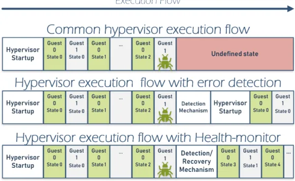
As Figure 1.1 exposes, there are three different hypervisor execution flows. The first one is the most common in TrustZone-based hypervisors. Due to its minimal
Chapter 1. Introduction 3 approach, the security is only based on error prevention.
Figure 1.1: Motivational execution flow.
The other two types imply extra mechanisms: error detection and recovery. In an implementation with error detection only, the hypervisor detects the error but the only feasible action is the full restart of the system. Although not ideal, this implementation already prevents the malfunction of the system for indeterminable time. With the addiction of the recovery mechanism, the system keeps the same but the throwback produced is reduced since it allows to recover from an healthy state closer to the current state of the system.
This thesis intent to provide a hybrid hardware/software fault tolerance mecha-nism with an Health-monitor, on an open source and an in-house TrustZone-based hypervisor, the Light-weight TrustZone-assisted hypervisor (LTZVisor).
1.2
Goals
The project reported on this thesis aims to achieve three primary goals decom-posable in more detailed sub goals:
1. Provide an exception handling to the LTZVisor. With this tool, the hypervi-sor user will know which part of the software is causing problems making the development more productive. The design of this feature needs to provide the following information:
4 Chapter 1. Introduction (a) Faulted World - If a fault occurs on the secure world or thenon-secure
World;
(b) Faulted processor mode - If the fault occur in Monitor mode or Super-visor.
(c) Fault type - If it is Data Abort or Prefetch Abort;
(d) Faulted subtype - If it is an alignment fault, cache maintenance, access fault, permission fault, and so on;
(e) Faulted address - The address that causes the fault.
2. Create a mechanism to detect secure memory evasive attacks. As the CLK-SCREW’s project [TSS17] shows, it is possible to change secure memory from non-secure side masking the ARM’s secure/non-secure bit, so the de-tection mechanism needs to:
(a) Distinguish a legitimate secure memory access from non legitimate se-cure access;
(b) Introduce the minimum of deterioration relative to the LTZVisor native performance.
3. Create a recovery mechanism responsible for recovering the hypervisor from memory failures with a minimum system throwback and completely LTZVi-sor independence, since the secure world is compromised. Although memory errors occur less often, they can be more disastrous and without an inde-pendent mechanism it cannot be handled without a full system reset. In order to be LTZVisor independent and not introduce any overhead, these mech-anisms should be hardware-based components making possible to run parallel mechanisms to detect non-legitimate memory accesses and full recover in case of failure.
1.3
Document Structure
This document structure serves the following order: Chapter 2 begins with an overview of the basic virtualization concepts, ARM Architecture and Trustzone technology, exception handling and Health-Monitors. It then proceeds by survey-ing existsurvey-ing hypervisors as well as their exception handlsurvey-ing and health-monitor implementations. This chapter ends with an introduction to hashes and checksum
Chapter 1. Introduction 5 algorithms, being these possible Health-Monitor mechanisms to detect memory faults.
Chapter 3 provides a more detailed description about the platforms: the board ZYBO Zynq-7000, with more indepth information about the DMA and AXI fea-tures, and the target hypervisor, the LTZVisor. Chapter 4 addresses the design and implementation of this project. Chapter 5 exposes the system evaluation and the discussion of the results. Lastly, Chapter 6 provides a summary of this the-sis, revealing the system limitations and from them outline solutions to future improvements.
2. Background, Context and State
of the Art
As the main theme of this thesis is error recovery on embedded systems’ hy-pervisors, this chapter will first expose a general definition of virtualization and hypervisors, ARM Architecture and TrustZone, exception handling and health-monitor, followed by some work done in this area. Even though there are many hypervisors, the focus will be on hypervisors that use hardware to assist
virtualiza-tion, i.e. LTZVisor, SafeG [saf], Jailhouse [Tec13] and VOSYSmonitor [LCP+17].
In fault tolerance and health-monitor section, the basic terminology and concepts are explained to better understand the project’s Health-Monitor implementation. Since the detection mechanism uses key comparison as sanity checker, the final part of this chapter will describe hash functions and checksums algorithms with the potential to be used.
2.1
Virtualization
The digital evolution is so accentuated that it is impossible to implement a modern system based on a simple Flip-Flop mindset due to the complexity re-quired. So to convert an high complex design into a compound of electrical sig-nals, the system needs to be analyzed as a hierarchy arrangement of abstraction layers and a well-defined interface between them [SN05]. At lower level, there is almost no abstraction since it is an electronic level. As we go up in the layers spectrum, the abstraction rise to the point that the layers become software based implementations such as code to run in the microcontroller, drivers to control the hardware or even Operating Systems (OS). They use the hardware infrastructure (communicating with the layers below) but in a such encapsulated way that they are unaware about how the hardware works.
The virtualization layer is responsible not only for hardware abstraction, but also enhances its features by creating unique virtual replicas of the hardware.
8 Chapter 2. Background, Context and State of the Art Thus, each software component has its own virtual replica. This makes possible to share the same hardware with different applications, run the same application on a different platform without large engineer efforts, or even distribute the same
application for different platforms [POP+17]. In some cases, the virtualization
layer also creates pure virtual components to meet the hardware requirements of the system. These replicas, also known as Virtual Machines (VMs), are described by Popek and Goldberg as an efficient and isolated replica of the real machine [PG74]. In the virtualization environment, two different terms, "host" and "guest" are used to distinguish where the software runs. The software that runs on the physical machine is called host software, and guest symbolises software that runs in a virtual world. The software responsible to create and monitor virtual machines on the host hardware is called a hypervisor or Virtual Machine Monitor. Popek and Goldberg [PG74] also describe this VMM as "a piece of software" with "three essential characteristics":
1. Equivalence: the provided virtualized environment should be essentially identical to the original machine. With this characteristic, guests OSs are directly used in VMs without any modification, minimizing costs of porting guest software to the VM.
2. Efficiency: It is a requirement that the virtual processor’s main instructions be executed directly by the real processor without intervention of the virtu-alization software in order to not substantially reduce the guest’ performance in relation to its native performance.
3. Resource Control: the VMM must have the full control of all system re-sources being impossible for a guest to monopolize or manipulate them. Only with a full resource control is possible to have the temporal and logical isolation between the machines.
Although the first hypervisor’s designs were bare metal hypervisors, there are currently two types of hypervisors described in figure 2.1: bare-metal hypervisors that run directly on the native hardware and hosted hypervisors that run on top of an OS. An example of hosted hypervisors are software as Oracle Virtual Box [ora] or Java Virtual Machine (JVM) [JVM] that enables different systems to run Java programs. Nonetheless, due to rigorous timing and low footprint systems, embedded systems demand bare-metal hypervisors.
Chapter 2. Background, Context and State of the Art 9
Figure 2.1: Hypervisor types. The hypervisors that run directly on
hardware are defined as Bare metal hypervisors (left) and the ones that run on top of OSs are Hosted hypervisors (right).
2.2
ARM Architecture
The ARM architecture is well suited for embedded systems due to simplicity that it present comparing other architectures. Consequently, simple implementa-tions lead to small implementaimplementa-tions, thus providing devices with low power con-sumption. The ARM architecture is a Reduced Instruction Set Computer (RISC) architecture, as it incorporates the following features [Lim12]:
• A large uniform register file;
• Load/store architecture, where data-processing operations only operate on register contents, not directly on memory contents;
• Simple addressing modes, with all load/store addresses being determined from register contents and instruction fields only.
Also, this architecture provides enrichments that supply a good balance between high performance and low resources demand like: instructions that combine a shift with an arithmetic or logical operation, auto-increment and auto-decrement addressing modes to optimize program loops, load and store multiple instructions to maximize data throughput and conditional execution of many instructions to maximize execution throughput.
ARMv7 is the seventh version of the ARM architecture and it provides three different profiles: A (Application), R (Real-time) and ARMv7-M (ARMv7-Microcontroller). They present different features in terms of memory. The
10 Chapter 2. Background, Context and State of the Art ARMv7-A supports a Virtual Memory System Architecture (VMSA) based on a Memory Management Unit (MMU). Contrary, ARMv7-R supports a Protected Memory System Architecture (PMSA) based on a Memory Protection Unit (MPU). Althought both architectures afford mechanisms to split memory into different regions, specifying memory types and attributes, the MMU provides a virtual memory system. This feature abstracts memory for different processes, allowing dynamic memory allocation by operating systems.
Depending on the desired application, the ARMv7 instruction set can be ex-panded with extensions in order to provide extra features:
• Security Extensions (SE) - Also known as Trustzone. This extension pro-vides a set of security features that facilitate the development of secure applications.
• Multiprocessing Extensions - This extension provides a set of features that enhance multiprocessing functionality. However, this is restrict to profiles ARMv7-A and ARMv7-R.
• Large Physical Address Extension (LPAE) - This extension provides an ad-dress translation system supporting physical adad-dresses up to 40 bits. The LPAE is restrict to ARMv7-A profiles with Multiprocessing Extensions en-able.
• Virtualization Extensions (VE) - This extension provides hardware support for virtualization with a virtual machine monitor, also called a hypervisor, to switch Guest operating systems. The VE requires the Secure Extensions extension.
2.2.1
ARM TrustZone
TrustZone is an hardware technology that allows the execution of guests with different levels of security in the same platform. On processors where VE is not available, TrustZone is considered the only hardware-based deployable approach in terms of virtualization. The TrustZone expansion to the new generation of
Cortex-M processors [WFM+07] proves that the technology is even spreading to
processors with limited resources.
With ARM TrustZone it is possible to separate the execution environment into two isolated worlds [Tru], allowing to run secure and non-secure applications in the same hardware. The 33rd processor bit (Non-Secure NS-bit) indicates the currently executing world. Also, some registers are baked for each specific world,
Chapter 2. Background, Context and State of the Art 11 which expedites the transitions between two worlds without compromise their isolation.
In terms of architecture, the main features of the Security extensions are: 1. Monitor mode - This extra processor mode is implemented with the purpose
of context switching between the Secure and Non-secure security states. Regardless the The Secure Configuration Register (SCR) secure bit, the software running in Monitor mode has access to both the Secure and Non-secure resources, even to system registers. Due to the high privileges, this mode only can be triggered by exceptions and by a special instruction named Secure Monitor Call (SMC).
2. Security Registers:
• Secure Configuration Register (SCR)- The SCR is the register responsi-ble to specify the security related parts of the system: the security state of the processor (Secure or Non-secure), for which mode the processor branches to if an IRQ, FIQ or external abort occurs (Abort mode or Monitor), and whether the Current Program Status Register (CPSR) F and A bits can be modified by the non-secure world.
• Secure Debug Enable Register (SDER) - The SDER enables secure invasive and non-invasive debug.
• Non-secure Access Control Register NSACR - The NSACR defines the Non-secure access permission to coprocessors.
• Vector Base Address Register (VBAR) - The VBAR holds the exception base address for exceptions that are not taken to Monitor mode. • Monitor Vector Base Address Register (MVBAR) - The MVBAR holds
the exception base address for all exceptions that are taken to Monitor. • Interrupt Status Register(ISR) - The ISR shows whether an IRQ, FIQ,
or external abort is pending.
3. Secure Monitor Call (SMC) - The only way that the non-secure world ac-cesses the secure world, which can be an access to data or routines, is through a special instruction called SMC. This instruction triggers an exception with predefined routines that run in monitor mode.
4. Exception model - With the addition of the monitor mode, two slightly different exceptions models are available that will be described on the next section.
12 Chapter 2. Background, Context and State of the Art
2.2.2
Exceptions in ARMv7 with TrustZone
There are eleven exceptions in ARMv7 with Trustzone: the common six of the ARMv7 architecture 1) Reset, 2) Data Abort, 3) Prefetch Abort, 4) Fast Interrupt (FIQ), 5) Interrupt Results (IRQ), 6) Undefined instructions; plus the 7) Secure Monitor Call (SMC), 8)/9) banked data aborts and 10)/11) banked prefetch aborts, for monitor and for non secure-side.
A data abort exception occurs when a data transfer instruction attempts to load or store data at an illegal address [Lin12] which can be unmapped memory, unaligned memory or inaccessible memory. Additionally, this exception takes place for errors related with paging and translation on virtual memory environments.
Although the prefetch exception also occurs on memory accessing errors, it
arises when the processor fetches an instruction from an illegal address. If a
pipeline architecture is present, the instructions already in the pipeline continue to execute until the invalid instruction is reached and then a prefetch abort is generated [Lin12].
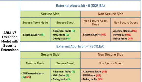
Figure 2.2 describes the two possible models that differ from each other in how external aborts are handled. In the first model (SCR.EA bit set to 0), external aborts are handled by an abort mode and each world is responsible to handle its own aborts. In the second model (SCR.EA bit set to 1), the Monitor is responsible to handle all external aborts regardless of the origin.
Figure 2.2: ARM-v7 with Security Extensions Exception Model. Two
models are described on the figure. At the model on the top, each world has an abort mode for itself. On the bottom model, the these exceptions are forced into the monitor despite the origin. Both modules share the
Chapter 2. Background, Context and State of the Art 13 As defined in ARMv7 Arquitecture Reference manual [Lim12], external aborts are "errors that occur in the memory system, other than those detected by the MMU or Debug hardware. External aborts include parity errors detected by the caches or other parts of the memory system." On other hand, the other aborts are more usual and by ARM design, they are handled by the respective supervisor (Guest OS) of each world in both models.
Despite some of the register are not dedicated only to interpret exceptions, the architecture provides five registers in order to understand the aborts’ origin:
• Saved Program Status Register (SPSR) has the purpose of saving the pre-exception value of the Current Program Status Register (CPSR), saving the processor status and control information that causes the exception. Since there is an SPSR for each processor mode, the CPSR is copied to the SPSR of the mode to which the exception is taken.
• Instruction Fault Status Register (IFSR) has the purpose of holding the status information about the last instruction fault. This register has two important parts: External bit (ExT), a bit that describes if it was an external abort or not; and Fault status bits (FS), five bits that describe the abort source. The valid encodings of these bits are present in the table 2.1. • The Data Fault Status Register (DFSR) is similar to IFSR but its purpose is
holding status information about the last data fault. Due to the similarity, the DFSR and IFSR share the same register structure and FS enconding values.
• The Instruction Fault Address Register (IFAR) has the purpose of holding the address of the access that caused a prefetch abort exception. Depending on the prefect abort source, this register can be invalid.
• The Data Fault Address Register (DFAR) is the data fault version of the IFAR.
Table 2.1: Fault Status encoding table. It is exposing the FS
encod-ing and correspondencod-ing exception source. On the column Abort type is expressed which aborts types are enable for each source. The DF means
Data fault and IF means Instruction fault.
Fault Status Source Abort type Note 00001 Alignment fault DF
-14 Chapter 2. Background, Context and State of the Art
00100 Fault on instruction cache
maintenance
DF
-01100 Synchronous external abort on
translation table walk - First level
DF & IF
-01110 Synchronous external abort on
translation table walk - Second level
DF & IF
11100 Synchronous parity error on
translation table walk - First level
DF & IF
-11110 Synchronous parity error on
translation table walk - Second level
DF & IF
-00101 Translation fault - First level DF & IF MMU Fault
00111 Translation fault - Second level DF & IF MMU Fault
00011 Access flag fault - First level DF & IF MMU Fault
00110 Access flag fault - Second level DF & IF MMU Fault
01001 Domain fault - First level DF & IF MMU Fault
01011 Domain fault - Second level DF & IF MMU Fault
01101 Permission fault - First level DF & IF MMU Fault
01111 Permission fault - Second level DF & IF MMU Fault
00010 Debug event DF & IF
-01000 Synchronous external abort DF & IF
-10000 TLB conflict abort DF & IF
-10100 Implementation defined DF & IF Lockdown
11010 Implementation defined DF & IF Coprocessor
abort
11001 Synchronous parity error DF & IF
-10110 Asynchronous external abort DF
-11000 Asynchronous parity error on
memory access
-Chapter 2. Background, Context and State of the Art 15
2.3
Hypervisors Implementations
This section describes some hardware-assisted hypervisors implementations, exposing its characteristics. After analysing the hypervisors, the section ends with a discussion of its similarities and differences.
2.3.1
LTZVisor
The Lightweight TrustZone assisted Hypervisor (LTZVisor) is an open-source hypervisor developed to seek the benefits and limitations of using TrustZone hard-ware to assist virtualization [LTZ]. The LTZVisor provides a virtualization solu-tion based on the two virtual execusolu-tion environments, Secure VM and Non-Secure VM. In the Monitor mode, this hypervisor provides software tools for virtualiza-tion like scheduler and an Inter-VM Communicavirtualiza-tion. Figure 2.3 describes these three main software components of LTZVisor’s architecture (the hypervisor, the secure VM and the non-secure VM).
Figure 2.3: LTZVisor General Architecture [PPG+17b]. The LTZVisor
hypervisor is a bare metal hypervisor and through TrusZone technology, it allows the concurrent execution of a GPOS and RTOS without violate
the isolation between both.
The design of this hypervisor is based on three principles [PPG+17b]:
• Minimal implementation - LTZVisor assures it by thoroughly relying on the hardware support of TrustZone technology since it reduces the software components needed to create a fully functional hypervisor without loosing the features.
16 Chapter 2. Background, Context and State of the Art • Least privilege - Access to the resources (e.g., I/O devices, system services, etc) is only allowed if absolutely necessary. This principle is guaranteed by ARM TrustZone design itself. As described in the Trustzone chapter, two different worlds are implemented in terms of privileges, allowing resources to be confined at one or both worlds at the same time.
• Asymmetric scheduling - The adoption of an asymmetric scheduling policy, where the secure environment has a higher privilege of execution than the non-secure one, will ensure that timing requirements are met, even while executing real-time tasks.
This hypervisor does not only guarantee processing and memory isolation, but also pledge the devices through Device Partition. The technology allows for the devices to be configured as secure or non-secure, as well as ensures isolation when the device is shared between the two worlds. Being the receptacle of this thesis, this hypervisor will be described more in depth in the next chapter.
2.3.2
Jailhouse
Jailhouse is an open-source, real-time, non-scheduling, fully functioning and Linux-based hypervisor. It combines the operating system Linux with isolated purpose components, minimising the hypervisor’s activity. Jailhouse was first developed by Jan Kiszka [Sin15] and later released to the public as open-source software. Despite this hypervisor is not TrustZone-based, it uses hardware to support virtualization.
The Jailhouse hypervisor’s core acts as a Virtual Machine Monitor (VMM), but due to its design, it implements resource access control rather than resource virtualization. Instead of virtually isolated worlds, the system reserves real cores. As Figure 2.4 shows, the resources are split in root cells and non-root cells. The difference between them are the privileges of cell management, offering cell cre-ation/destruction and hypervisor disabling tools to the root cells.
Although the GPOS in most cases are considerer non-privileged by other hy-pervisors, in this case the Linux is the root cell guest since it cooperates closely with Jailhouse. The other cells can be baremetal applications or RTOSs. In-stead of sharing symmetrically multi-core processor resources between guests, this hypervisor drives each guest with their own set of resources [Sin15]. Thus, it implements Asymmetric Multiprocessing (AMP) without losing isolation.
Chapter 2. Background, Context and State of the Art 17
Figure 2.4: Jailhouse hypervisor Overview, based on [Kis14]. The
Jail-house hypervisor divide its guests in root (Linux) and non-root cells (bare-metals and RTOSs). The root cell, defined as green on figure, is privileged in terms of controlling the resources. Since this hypervisor do not provide resource sharing, the non-root cells (represented in light blue) are limited
to used the resources provided by the root cell.
Despite of being a bare metal hypervisor, this Jailhouse is Linux dependent since it is the system that provide boot and hardware initialization. After the inicialization, the hypervisor acquire all the hardware resources (e.g., CPU(s), memory, PCI or MMIO devices), removes them from Linux and reassigns them to the new domain (other cell). Since Jailhouse only remaps and reassigns resources, once everything is set up, its ideal execution would to be only intervene if there was a case of access violation [RKLM17].
2.3.3
SafeG
SafeG was designed by TOPPERS[saf] as a dual-OS TrusZone-based monitor with the purpose of executing a RTOS and a GPOS concurrently. Like other Trustzone-based hypervisors, it relies on Trustzone for isolation and on the new processor mode (Monitor) to perform switches between the Trusted and Non-Trusted worlds. In this mode, the interrupts are disabled making it deterministic [SHT13].
18 Chapter 2. Background, Context and State of the Art One of the key features of this hypervisor is the full control of RTOS over the GPOS actions and scheduling time, making possible to implement a hypervisor independent scheduler. As shown in Figure 2.5, the scheduler slices the time into two different parts: RTOS running time and Cyclic Sched. The first one is reserved only for RTOS tasks while in the Cyclic Sched slice the processor can
switch between guests. Like other VMMs oriented to real-time systems [YLH+08],
the GPOS is only executed when the RTOS becomes idle, and in that time, the RTOS schedules the GPOS as a normal RTOS task [SHT13] since it is responsible for scheduling.
RTOS
Cyclic
Sched
RTOS
Cyclic
Sched
RTOS
Cyclic
Sched
R T O S G P O S R T O S G P O S R T O S G P O S Context SwitchFigure 2.5: SafeG scheduler, based on [SHT13]. The SafeG scheduling
policy is divided in two periodic slices: The RTOS scheduling time (rep-resented in blue) and a Cyclic Sched (rep(rep-resented in white). The first portion is fully reserved to RTOS as long as in the Cyclic Sched, the RTOS can schedule the GPOS (represented in yellow) as well as its own
tasks.
2.3.4
VOSYSmonitor
VOSYSmonitor [VOS], developed by Virtual Open Systems [LCP+17], is a
software monitor which enables, just as the others aforementioned, the concurrent execution of a safety critical RTOS along with a GPOS. The VOSYSmonitor, simi-larly LTZVisor, was designed using the TrustZone architecture, insuring by design peripherals and memory isolation between both OSs, but allowing dynamical cores sharing.
Since the main goals of the VOSYSmonitor are performance related, the boot time is taken into consideration. By design, the VOSYSmonitor setup must be achieved in less than 1% of the full RTOS boot time. For instance, a RTOS boot time of 60 ms implies a setup performed in less than 600us regardless of the
platform [LCP+17]. Additionally, the context switch is simplified. This hypervisor
Chapter 2. Background, Context and State of the Art 19 minimises context switches. Even so, most of the code executed is written in ARM assembly and only vital registers are saved in these switches.
2.3.5
Discussion
Being hardware-assisted hypervisors, it is possible to identify common design features:
• All support concurrent execution of a GPOS and an RTOS.
• They take advantage of hardware extensions in order to achieve isolation between guests, a low footprint hypervisor and very low execution overhead. • Due to TrutZone design, they separate IRQs for the non-secure world and
FIQs for the safe world.
• They provide time isolation of the RTOS creating a deterministic behavior for him.
Regarding interrupts, the analysed hypervisors separate IRQs for the non-secure world and FIQs for the non-secure world because through TrustZone design is possible to prevent the non-secure world side from disabling FIQ interrupts (IRQs can be disabled) and IRQs can be treated without the intervention of the secure world.
As for hypervisors like VOSYSmonitor and LTZVisor, when the processor is running in the secure world, the IRQs are turned off as it is considered that no interruption from the non-secure world should stop the normal working of the secure world. Nevertheless, when the processor is running in the non-secure world both IRQs and FIQs are enabled and FIQs have higher priority than IRQs because of their origin.
The Jailhouse is the hypervisor that provides most differences in terms of design due to the fact that the most privileged guest is the Linux. In summary, it is possible to conclude that the Jailhouse is a tool to extend hardware virtualization to Linux providing full guest control without loosing system performance.
2.4
Exception Handling
Anomalies may occur during program execution. Exception handling is the se-lection of handlers with predetermined actions to respond to those anomalies. Due to the fact that the exceptions can differ depending on the processor architecture, this work will focus on exceptions from ARMV7 without VE.
20 Chapter 2. Background, Context and State of the Art
2.4.1
Exception Handling Implementations
Even though this section is about exception handling implementation in hy-pervisors, it will only bring to light SafeG handlers due to the architecture in-compatibility of the others. Both Jailhouse and VOSYSmonitor are designed to run in ARMv7 with Virtualization Extensions or ARMv8 altering completely the exception handling design. These technologies provide levels of exceptions that separate monitor, guest and application exceptions, contrary to the ARMv7 with SE that provides only one for each world.
2.4.1.1 SafeG
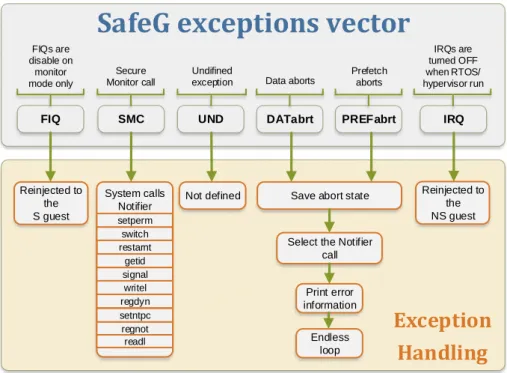
Figure 2.6 illustrates the exception handling overview of SafeG hypervisor. It follows the normal design of the ARM-v7 architecture exceptions. The Undefined handler is a simple endless loop due to the difficult of understanding the origin and the exception consequences. Like the LTZvisor, this hypervisor is designed to define FIQs as secure interrupts and IRQ as a non-secure interrupts. To accomplish hypervisor atomicity, the FIQs are disabled when the processor is on monitor mode (when the tasks of the hypervisor are running) so they stay pendent until one of the guest is active. Like FIQs, the IRQs are disabled on monitor mode but also when the secure guest is running. This guarantees that the secure world is not interrupted by the non-secure guest. Only when the non-secure guest is functioning, in this case the GPOS, the IRQs are enabled and attended.
This hypervisor has a list of APIs that both secure and non-secure guest can call through Secure Monitor Call (an exeption to call the monitor) in order to configure some hypervisor features. They are monitored by the Notifier module, which is designed to avoid race conditions and security leaks. This module allows the creations of dynamic system calls by the secure guest but by default, the Notifier defines ten system calls:
• setperm - set permissions for a certain system call. • switch - initiates a switch to the opposite world. • restarnt - restart NT OS
• getid - return the ID of a system call.
• signal - signals an interrupt to the opposite world. • writel - write specific address
• regdyn - register a dynamic system call. • setntpc - set NS OS Program Counter • regnot - register a notifier call.
Chapter 2. Background, Context and State of the Art 21 • readl - read specific address
FIQ SMC UND
SafeG exceptions vector
Save abort state
Exception
Handling
IRQ
Select the Notifier call Reinjected to the NS guest DATabrt PREFabrt Not defined Print error information Endless loop Reinjected to the S guest System calls Notifier Undifined exception Secure Monitor call FIQs are disable on monitor mode only IRQs are turned OFF when RTOS/ hypervisor run Prefetch aborts Data aborts getid setperm switch signal regdyn regnot readl writel restarnt setntpc
Figure 2.6: SafeG hypervisor Exception Handling Overview. This
hy-pervisor has five defined exceptions (represented in grey): FIQ, IRQ, SMC, Data aborts and Prefetch aborts. The handlers are defined in
or-ange.
To handle data aborts and prefetch aborts, this hypervisor provides the possi-bility of using guest handlers previously registered in the Notifier. If it is empty, the SafeG prints the error information and jumps to an endless loop.
2.5
Fault tolerance concepts and Health-monitor
The fault tolerance can be simply defined as the prevention of faults from becoming failures [ASTM08]. Since these terms are wrongly often used as syn-onyms, as they describe different concepts, a detailed description of them is needed [ALRL04]. Also the terms Reliability and Availability are important to define due to fact that they characterize the system performance in terms of fault tolerance [ASTM08].
• Faults - A fault is the defect that causes the error.
• Errors - An error is a corrupted system state that may cause a subsequent failure.
22 Chapter 2. Background, Context and State of the Art • Failures - A failure is an event that occurs when a system deviates from
the correct work flow.
• Reliability - probability that a system will perform its intended function satisfactorily, for a specified period of time.
• Availability - probability that a system is performing its required function at a given point in time.
Implementation of fault tolerance involves in two different subsystems: er-ror detection and system recovery. Erer-rors detection can be a watchdog, to de-tect abused deadlines, or a more complexing mechanism like DFI (Data Flow Integrity)[LMTP18] and CFI (Control Flow Integrity)[WJ10] that detects not-expected data and instructions flows. System recovery aims to eliminate the error from the system state and may diagnose the fault, preventing it from being reac-tivated. The complexity of the mechanism is increased with the fault tolerance classification of the system. Critical systems in which a failure can cause life losses, the system’s availability and reliability needs to be as high as possible [Sie91]. Im-proving the fault tolerance usually depends on implementing extra error detection mechanisms and even redundancy, features that add more variables to the system cost equation: cost/reliability and cost/availability.
2.5.1
Basic techniques in error handling
After the detection of an error state, the recovery system is triggered to solve the error. There are three general techniques for error handling: backward recov-ery, forward recovery and compensation.
• The backward recovery, also known as rollback technique, is a technique in which the system is restored to a previous assumed error-free state. In this technique, the system state is stored periodically in predetermined
check-points, to be able to recover from them [Cri82][XRR+95][RP12].
• In the forward recovery, also called rollforward technique [RLT78], the sys-tem is taken from an error state to a healthy state but by rolling forward to a future checkpoint. Since the roll is not a rollback, the deadlines and real-time constrains are not corrupted. This technique is more system de-manding due to the predictable behaviour needed on checkpoints creation [XR96].
Chapter 2. Background, Context and State of the Art 23 • In the compensation technique, the system contains enough redundant in-formation so that an error do not compromise it’s normal flow. Normaly, this technique do not depend on error detection but due to the multiples implementations of the critical parts.
2.5.2
Hypervisor’s Health-monitors and Recovery
mecha-nisms
The hypervisor’s health-monitor is responsible to monitor the hypervisor’s work flow or, in other words, it is the hypervisor’s fault tolerance mechanism. During hypervisor’s execution, the Health-monitor will compare the hypervisor’s actions with it own patterns or redundant parts of itself in hardware. Not only the actions but the hypervisor’s time spent on them can be monitored to control his sanity. If the Health-monitor detects issues with the hypervisor, the Recovery System activates the mechanism to restore the hypervisor to a healthy state.
Using the above definitions, the health-monitor main job is to detect errors as soon as possible to prevent failures and restore the system to a healthy state, eliminating faults and improving the system’s reliability and availability.
Concerning health-monitor implementations, hypervisors’ health-monitors are limited since the main goal is to achieve a system with very low execution overhead. The sections below describe health-monitors implementation in hypervisors.
2.5.2.1 SafeG
The SafeG hypervisor supports a GPOS health monitoring with the ability to monitor, suspend, resume and restart the GPOS from the secure world side (RTOS). Monitoring the GPOS status from the RTOS is possible because the GPOS resides in Non-Trust space memory, which is accessible from Trust state. To support GPOS interrupt monitoring (when appear, the frequency and inter-arrival time), IRQs are first processed by SafeG, which implements a Secure Monitor mode vector table, before being forwarded to the GPOS.
2.5.2.2 VOSYSMonitor
The VOSYSMonitor developed a secure world monitoring mechanism, despite not being present in the latest versions of this hypervisor. The developed mecha-nism was based on a watchdog turned on whenever the processor entered the safe world. With each context switch, this counter is reset, measuring only the safe
24 Chapter 2. Background, Context and State of the Art world processor’s time. This watchdog would activate a reset in the safe world if the time was greater than a certain threshold.
2.5.2.3 Discussion
Despite of the presented health monitors being taken into consideration, only one of them shares this thesis goal. SafeG provides a mechanism to control the GPOS from the secure side. This feature is considered a Health Monitor since it controls and monitor the non-secure guest health. However, it does not improve the secure world security.
The watchdog introduced by VOSYSMonitor’s developers aims to control the time spent in the secure world execution, which completely removes the possibility of running non-secure code in the secure world schedule window. But as described in the hypervisor’s presentation document, the mechanism failed for two reasons
[LCP+17]: 1) Turning watchdog on and off adds a significant overhead to the
context switch; 2) The ARM Physical Secure Timer was chosen for the watchdog, but due to the interrupts being treated as IRQs they can no longer be turned off once the processor is in secure mode, thus breaking the design of the hypervisor itself.
2.6
Non-Encrypted Hash functions and
Check-sums
In order to detect error states, this thesis sanity check is based on secure memory patterns. To detect secure memory faults it compares the current memory state with a sane state. In order to reduce time and resources of comparing all the of bytes of memory, it compresses the memory states into keys. Although this task will be implemented in hardware, the function to convert states to keys have to follow two main metrics: fast conversion and easy implementation. The two metrics are interconnected with each other in the following way of if the conversion is a complex algorithm, it can compromise the fast conversion metric. The conversion occurs twice per context switch, one for the healthy state and one for the unknown state, which it is mandatory to be as fast as possible. The second metric removes encryption algorithms from the list since they turn to be more complex. Also, considering that the generated keys are not accessible from outside of Health-monitor, the encryption is useless.
Chapter 2. Background, Context and State of the Art 25 Due to the simplicity of the non-encrypted hash functions and the checksums, the sections below describes some of them.
2.6.1
FNV-1 and FNV-1a
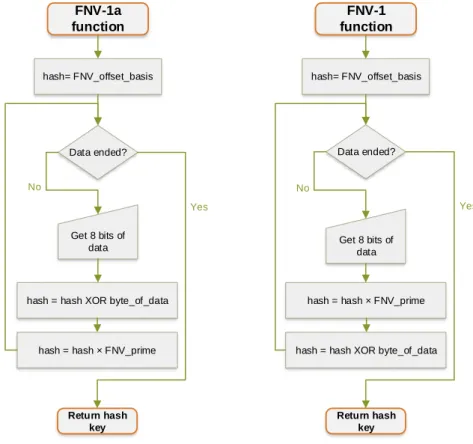
The Fowler–Noll–Vo or FNV is a hash function created by Glenn Fowler, Lan-don Curt Noll, and Kiem-Phong Vo designed to be fast while maintaining a low collision rate [Lan]. They took the main idea from a comment reviewing the IEEE POSIX P1003.2 in 1991 and due to the speed of the algorithm, it is used to hash large data. The flowcharts below describe the basic algorithm composed by a multiplication and an multiplexer operation, and the constants FNV_prime and FNV_offset_basis. The FNV-1a is a FNV-1 alternative hash function that differs only in the order of the operations. The FNV_prime constant consists on a prime number and it is dependent of the size of the key. The FNV_offset_basis is an
offset to achieve better dispersion [FNV+11].
FNV-1a function Data ended? Yes No Return hash key hash= FNV_offset_basis Get 8 bits of data
hash = hash XOR byte_of_data
hash = hash × FNV_prime
FNV-1 function Data ended? Yes No Return hash key hash= FNV_offset_basis Get 8 bits of data
hash = hash × FNV_prime
hash = hash XOR byte_of_data
Figure 2.7: FNV-1a and FNV-1 algorithms flowchart. On the left, the FNV-1a hashes eight bits of data per cycle by executing: 1) a XOR operation between the byte and the previously produced hash key, 2) a multiplication between the resulting number and a predefined prime number. The function ends when all the data is fully hashed. On the right algorithm, the basics are the same but the operations are swapped.
26 Chapter 2. Background, Context and State of the Art To simplify the selection of the right constants for the hash function, the cre-ators afford a table with the best pair (FNV_prime and FNV_offset_basis) for each desired size of the key.
Table 2.2: Suggested values for FNV constants
Size in
bits FNV prime FNV offset basis
32 16777619 0x811c9dc5
64 1099511628211 0xcbf29ce484222325
2.6.2
SDBM
The SDBM hash algorithm was created for SDBM [SDB] database library that is a public-domain reimplementation of NDBM. NDBM is an Application Programming Interface (API) made to maintain key/content pairs in a database and it uses hash functions to allow a programmer store keys and data in the database tables. As it is possible to see in the flowchart of Figure 2.9, the function is a compound of simple mathematical operations and binary shifts.
Data ended? Yes No Return hash key Get 8 bits of data
hash= data + (hash << 6) + (hash << 16) - hash
SDBM function
Figure 2.8: SDBM algorithm flowchart. The SDBM hash function is
a manipulation of the previously produced key plus the input data un-touched. It hashes eight bits of data per cycle and ends when all the data
Chapter 2. Background, Context and State of the Art 27
2.6.3
DJB2
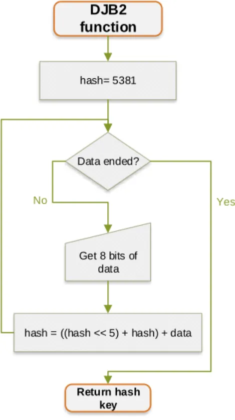
The DJB2 hash function was reported by the mathematician and computer scientist Dan Bernstein in an open group with the form of X = ((a × X) + c) mod m, where the X is the value produced, c the "increment", a a multiplier constant and m the "modulus" that truncates the output value.
This function is similar to LCG (Linear Congruential Generator) functions which are a class of functions that generate pseudo-random numbers proving the
good dispersion of values produced [Knu97]. With an m of 232 and the constant
a having the value of 33 the function can be converted into a less operations
demanding form: X = (X << 5 + X) + c. DJB2 function Data ended? Yes No Return hash key hash= 5381 Get 8 bits of data
hash = ((hash << 5) + hash) + data
Figure 2.9: DJB2 algorithm flowchart. This algorithm uses the 5381
number as the start-up key value in order to achieve a better distribution. It hashes eight bits of data per cycle and ends when all the data is hashed.
2.6.4
Murmur
Austin Appleby created the Murmur hash in 2008 and since then several vari-ants and versions of this hash were made and submitted online [App08]. The main difference from the others hashes to this one is the number of input bytes (8 bits for the others and 32 bits for this one) for each generated key. This characteristic
28 Chapter 2. Background, Context and State of the Art reduces the number of cycles needed to hash the same amount of data to a quarter but increase the hardware needed due to the redundancy. Figure 2.10 exposes the algorithm which despite the number of operations, it can be fast since some of them can be parallel operations due to their independence.
FourthByte= (FourthByte × 0xcc9e2d51) ROL 15
FourthByte= FourthByte × 0x1b873593
hash = (hash XOR FourthByte) ROL 13
hash = hash × 5 + 0xe6546b64
hash = hash XOR remainingBytes
hash = hash XOR 4
hash = hash XOR (hash >> 16)
hash = hash × 0x85ebca6b
hash = hash XOR (hash >> 13)
hash = hash × 0xc2b2ae35h
hash = hash XOR (hash >> 16) Murmur function Data ended? Yes No Return hash key hash= 5381 Get 32 bits of data remainingBytes= (remainingBytes × 0xcc9e2d51) ROL 15 remainingBytes= remainingBytes × 0x1b873593
Figure 2.10: Murmur algorithm flowchart. This algorithm hashes 32
bits of data by modifying its fourth byte and the remaining ones in parallel operations. The key produced by Murmur algorithm is a 32 bit key.
Chapter 2. Background, Context and State of the Art 29
2.6.5
CRC32 Checksum
CRC checksum was first proposed by W. Wesley Peterson in 1961 with the purpose of use redundancy for error detection in communication networks [PB61]. In this algorithm, the generated key results from a polynomial long division, where the message is the dividend, the polynomial is the divisor and the quo-tient is discarded. To reduce the time of the calculation, the implementation of this checksum uses a lookup table with the constants of the generator polynomial. Figure 2.11 describes the CRC32 algorithm that is a variant of this checksum for a 32 bits output value and also the lookup table algorithm. The variable pos is the table index used to get the right value from the lookup table.
CRC32 lookup table index=0 Index=256? Yes No crc = index << 24 J=8? Yes No J=J+1 crc = crc << 1 J=0 table[index] = crc end Index=Index+1 (crc & 0x80000000) != 0? Yes No crc = crc XOR 0x04C11DB71 crc = crc << 1 Data ended? Yes No Return value Get 8 bits of data CRC32 function crc = 0xFFFFFFF
pos = (char) ((crc XOR (data << 24)) >>24)
crc = (crc << 8) XOR table[pos]
Figure 2.11: CRC32 and respective lookup table flowcharts algorithms.
On the left is represented the CRC32 algorithm simplified by its lookup table. On the right, the algorithm to produce the lookup table.
30 Chapter 2. Background, Context and State of the Art
2.6.6
Discussion
Although all algorithms share the same property of conversion of an input value to a shorter output value, CRCs and hash functions have different design purpose. The CRCs are designed to detect not forced errors in data [PB61] while general purpose hashes, like the above algorithms, are optimized to reduce bias in the output value even when the input is biased. Even if the CRCs algorithms are designed for error detection, the origin of hypervisor errors is unknown (they can be forced to errors on the NS side), which makes CRC a not so ideal option.
3. Platforms and Tools
This chapter exhibits the groundwork platforms that support this thesis. First will be described the Zybo board, the Zynq device where the entire system, LTZVi-sor plus Health-monitor is deployed. Lastly, will be exposed the LTZViLTZVi-sor, the hypervisor on which the exception handler is implemented.
3.1
ZYBO Zynq-7000 SoC
The Zybo (Zynq Board) is an entry-level embedded software and digital circuit development platform developed by DIGILENT [DIL] . This board is built around the Xilinx All Programmable System-on-Chip (SoC) Z-7010, which integrates a dual-core ARM Cortex-A9 processor with Xilinx [XIL] 7-series field programmable gate array (FPGA) logic. Attached to the processor and the FPGA, this board provides a rich set of multimedia and connectivity peripherals. To expedite the system design and deployment on the board, the Xilinx’s Vivado [Viv] Design Suite as well as the ISE/EDK toolset provide full compatibility with this board. These features make the Zybo a complete development kit to handle diverse projects with no additional hardware needed.
3.1.1
Zynq-7000 family
As it is possible to see in Figure 3.1, Zynq-7000 family integrates two dis-tinct systems: The Processing System (PS) and the Programmable Logic (PL). The first one is composed by resources to handle software: Dual or single-core
ARM CortexR TM-A9 MPCore; On-chip memory; External memory interfaces;
I/O peripherals and Programmable Logic interconnects.
The PL provides configurable logic in order to create dedicated hardware: con-figurable logic blocks (CLBs); concon-figurable ports to the block RAM (BRAM); DSP slices with a 25 x 18 multiplier and 48-bit accumulator; an user configurable ana-log to digital convertor (XADC); Clock management tiles (CMT); a configuration

![Figure 2.3: LTZVisor General Architecture [PPG + 17b]. The LTZVisor hypervisor is a bare metal hypervisor and through TrusZone technology, it allows the concurrent execution of a GPOS and RTOS without violate](https://thumb-eu.123doks.com/thumbv2/123dok_br/17268276.788965/41.892.261.665.571.848/ltzvisor-architecture-ltzvisor-hypervisor-hypervisor-truszone-technology-concurrent.webp)
![Figure 2.4: Jailhouse hypervisor Overview, based on [Kis14]. The Jail- Jail-house hypervisor divide its guests in root (Linux) and non-root cells (bare-metals and RTOSs)](https://thumb-eu.123doks.com/thumbv2/123dok_br/17268276.788965/43.892.271.679.122.526/figure-jailhouse-hypervisor-overview-hypervisor-divide-guests-linux.webp)
![Figure 2.5: SafeG scheduler, based on [SHT13]. The SafeG scheduling policy is divided in two periodic slices: The RTOS scheduling time (rep-resented in blue) and a Cyclic Sched (rep(rep-resented in white)](https://thumb-eu.123doks.com/thumbv2/123dok_br/17268276.788965/44.892.144.710.406.599/figure-scheduler-scheduling-divided-periodic-scheduling-resented-resented.webp)