IEEE Proof
Web Version
Mirror-Integrated Transparent Antenna
for RFID Application
Cristina C. Serra, Carla R. Medeiros, Jorge R. Costa, Senior Member, IEEE, and
Carlos A. Fernandes, Senior Member, IEEE
Abstract—An optically transparent antenna array is presented
for radio frequency identification (RFID) systems, operating in the ultrahigh frequency (UHF) band. The antenna is intended for non-intrusive integration into the mirror surface of fitting rooms in ap-parel stores, keeping with the typical small depth of the mirror structure and low cost. The antenna is used to read RFID tags at-tached to clothes being tried on, so that the associated system can automatically provide the client with interactive information re-garding that specific piece of clothing. The antenna ensures self-confined reading range in front of the mirror, avoiding undesired detection of RFID tags from adjacent fitting rooms. The final an-tenna solution shows a good compromise between transparency and performance, with well-confined RFID detection volume.
Index Terms—Printed antenna, radio frequency identification
(RFID), reader antenna, tag, transparent antenna.
I. INTRODUCTION
R
ADIO frequency identification (RFID) technology en-ables automatic detection and identification of physical objects through radio waves. A tag with a univocal code is asso-ciated with each object, making identification possible without human intervention. Using frequency bands from high fre-quency (HF) to microwaves, the deployment of RFID systems has increased considerably, being extensively used for automa-tion improvement, inventory control, antitheft, and checkout operations in stores, factories, and warehouses [1]–[3]. Toll systems or electronic passports are just a few of many applica-tions of RFID technology.Passive RFID tags operating in the ultrahigh fre-quency (UHF) band are getting increased attention for mass retail applications because of their very good sensitivity and low cost [4]. This technology presents several opportunities, for instance in clothing stores. One such case would be the possibility to automatically read the tag associated with a piece of clothing being tried on in front of a mirror and, based on that information, the associated system would supply the client
Manuscript received June 29, 2011; accepted July 20, 2011. This work was supported in part by Fundação para a Ciência e Tecnologia under Project RFID-Local PTDC/EEA-TEL/102390/2008.
C. C. Serra, C. R. Medeiros, and C. A. Fernandes are with the IST, Insti-tuto de Telecomunicações, 1049-001 Lisboa, Portugal (e-mail: cristina.camara. [email protected]; [email protected]; [email protected]).
J. R. Costa is with the IST, Instituto de Telecomunicações, 1049-001 Lisboa, Portugal, and also with the Departamento de Ciências e Tecnologias da Infor-mação, Instituto Universitário de Lisboa (ISCTE-IUL), 1649-026 Lisboa, Por-tugal (e-mail: [email protected]).
Color versions of one or more of the figures in this letter are available online at http://ieeexplore.ieee.org.
Digital Object Identifier 10.1109/LAWP.2011.2163053
with added functionalities, such as a list of available sizes and colors of that item or other matching garments.
There are currently some solutions based on this idea [5], but none of these address the key challenges: to ensure that the cov-erage of the reader antenna is solely confined to the fitting room (or to the volume in front of the mirror), that the assembled so-lution is shallow and nonintrusive like an ordinary mirror, and most importantly, that it is very low-cost. The solution presented in this letter not only guarantees the desired detection confine-ment without physical barriers, but also ensures invisibility of the antenna and cables. This feature is attractive for aesthetical reasons and to avoid that clients feel uncomfortable with un-usual devices in the fitting room.
The antenna cannot be hidden behind the mirror because this is not electromagnetically transparent. Therefore, we propose in this letter to print a transparent patch antenna on the glass sur-face of the mirror and couple energy to it from behind through a slot in the mirroring layer without front cables and soldering points.
There are currently several possible materials to create transparent antennas, like spray-on conductive substances [6] or metallic conductive films. However, most of these materials do not present the best optical transparency for the mirror application. Indium tin oxide (ITO) films seem to be the most viable solution so far, for they present the best compromise between optical transparency and electrical conductivity. Even though the associated Ohmic losses reduce the performance of the antenna, there are ways, such as some particular deposition techniques [7], to improve conductivity.
This letter is divided into three sections that include the anal-ysis of ITO samples for the transparent antenna, antenna char-acterization, and experimental confirmation of its performance for RFID tag detection.
II. ITO FILMCHARACTERIZATION
Different types of commercially available ITO sheets were evaluated in order to select the adequate surface resistivity and layer thickness for acceptable antenna radiation efficiency. Used samples of ITO consisted of glass substrate ( ,
, , and thickness 1 mm) with different ITO coatings.
Manufacturers specify the electrical properties of thin conductive films through the sheet resistance in sq and coating thickness [8]. A key point is to correctly model low-conductivity thin films in commercial electro-magnetic (EM) solvers. In order to validate this modeling, the insertion loss of a simple 50- microstrip line (width cm and length cm) with ITO film as the
IEEE Proof
Web Version
2 IEEE ANTENNAS AND WIRELESS PROPAGATION LETTERS, VOL. 10, 2011
Fig. 1. Simulated ( ) and measured ( ) -parameters of the ITO mi-crostrip line with sq, nm, and length 20 cm.
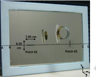
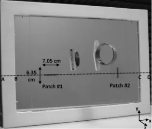
Fig. 2. Array of ITO patch antennas incorporated in the mirror. The represented dimensions correspond to the size and position of the ITO patch, which is imper-ceptible in the photo due to its high transparency. A tagged bracelet is reflected on the mirror.
conducting strip was studied using CST-MWS Frequency Solver [9] for different combinations of and . The simula-tion model for the ITO film was improved after comparing the corresponding results to measurements on experimental coun-terpart structures, namely in respect to substrate permittivity.
Conductivity relates to previous parameters as , so for a given film thickness, the microstrip line presents the lowest insertion loss for the lowest sheet resistance. An ITO film from Visiontek Systems [8] with sq and nm was selected for the antenna. This thickness represents a compromise in terms of optical transparency. The -parameters of the corresponding test ITO microstrip line are presented in Fig. 1, anticipating the possible losses of the antenna in the UHF band.
III. SIMULATIONS ANDTESTS
A small 52 35 cm mirror integrating a two-element array is considered for proof of concept (see Fig. 2). An ordinary mirror is used, with glass thickness mm, , , and . An aperture-coupled rectan-gular ITO patch antenna configuration is adopted for the array elements because of its simplicity of fabrication and integra-tion into the mirror structure. The mirroring layer is used di-rectly as the antenna ground plane, where the coupling slots (width cm and length cm) are opened. Unlike other reported transparent antennas where a lossy transparent
Fig. 3. Feeding circuit printed on Duroid 5880 substrate (thickness 1.57 mm) at the back of the ITO patch antennas and back of the mirror.
microstrip line is used for edge feeding [10], the present an-tenna uses a low-loss conventional 50- microstrip line cir-cuit (width 5 mm) printed on Duroid 5880 substrate to excite the slots (see Fig. 3) from behind the mirror. Feeding line #1 is 34.3 cm long, and feeding line #2 is 40.6 cm. Tuning stubs are added to maximize power coupling to the patch. The ITO patches are printed on a separate 1-mm-thickness glass sub-strate (characterized in Section II): The glass subsub-strate with the ITO thin film was bathed in a solution of chloride acid plus zinc, which removed the ITO layer except in the regions pro-tected with resistant enamel, according to patches shape and position. This glass slab with the ITO patches is juxtaposed on the mirror. The whole assembly, including the feeding circuit, is just 6 mm thick. Since the ITO layer has very high optical transmittance, the full mirror area is almost uncluttered. This is confirmed in the photograph of Fig. 2, where the ITO patches are imperceptible.
Linear polarization from the adopted patch configuration re-stricts orientation of common linear polarized tags. In order to minimize this restriction, the two patch antennas in the mirror are rotated by 90 with respect to each other, while the feed cir-cuit introduces quadrature phase difference. The combined ra-diation from the two patches favors better tag detection regard-less of its orientation. The distance between the two patches is chosen to obtain the best uniform field coverage in front of the mirror. The filed distribution is presented ahead.
Comparisons between measured and CST-MWS simulated return loss results are presented in Fig. 4. Some difference between modeled and measured -parameters is partly due to the difficulty to model thin films and partly because the stubs lie very close to the slot, resulting in strong sensitivity to manufacturing inaccuracies. Results show that the antenna can operate over the several international UHF RFID bands (860–960 MHz).
Simulations also show that gain and radiation efficiency are very low (gain dBi and radiation efficiency
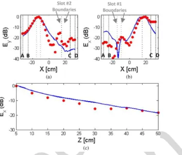
), but still they are typical for transparent antennas. In order to further asses the simulation model and evaluate the array performance, near-field calculations are presented at 865 MHz and compared to measurements. The near-field dis-tribution at the plane (5 cm away from the mirror) and at the plane (cut following the ABCD line shown in Fig. 2) is represented in Fig. 5. As expected, the dominant component over slot #1 is and over slot #2 is , in agreement with slot
IEEE Proof
Web Version
Fig. 4. Simulated and measured -parameter of the ITO patch antennas in-corporated in the mirror.
Fig. 5. Simulated near-field components in front of the mirror: (a) cm plane; (b) -plane containing the ABCD line ( cm).
orientation. The rate of field decay in the near-zone can be seen in Fig. 5(b). The figure also shows that the distance cm between the center of the patches is appropriate to produce an even field distribution in front of the mirror. It will be shown ahead that this confinement is interesting not only because it is short-range, but also because of the shape of the illuminated region.
The near-field distribution was confirmed experimentally (see Fig. 6) across the ABCD cut at cm and along the -coordinate. A reasonable agreement is obtained between measurement and simulation.
IV. RFID TESTS OF THEARRAY
Tag detection tests were performed in order to confirm that the developed solution is fit for real RFID applications. A com-mercial RFID reader (Sirit INfinity 510 [11]) was connected to the antenna port, and an RFID tag was displaced systematically in front of the mirror for all directions and distances until the
Fig. 6. Simulated ( ) and measured ( ) normalized near-field compo-nents of the mirror: (a) component at a plane with cm and over the ABCD line ( cm); (b) component at a plane with cm and over the ABCD line ( cm); (c) component over slot #2 ( cm and cm).
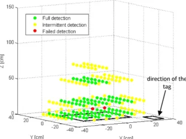
Fig. 7. Tag readings of the array of ITO patch antennas fully incorporated in the mirror (orientation 1).
reader could no longer detect it. For this test, a linearly po-larized passive tag was used from Alien Technology (ALIEN ALN-9540 “Squiggle” [12], shown reflected on the mirror in Fig. 2). Results are presented in Figs. 7 and 8. Two orthogonal orientations of the tag are shown in order to characterize the antenna permissibility to tag orientation. The origin of the coor-dinate system corresponds to the center of the array, with being the level of the ground plane. The power delivered to the antenna was kept constant for all tests (1 W) to allow direct com-parison of the results.
Tag readings are classified under three categories: full detec-tion, intermittent detecdetec-tion, or failed detection. Full detection corresponds to reliable tag reading over at least 2 s (which is equivalent to approximately four readings); tag readings during less than 2 s are labeled as intermittent detection; failed detection corresponds to absence of readings. The results in
IEEE Proof
Web Version
4 IEEE ANTENNAS AND WIRELESS PROPAGATION LETTERS, VOL. 10, 2011
Fig. 8. Tag readings of the array of ITO patch antennas fully incorporated in the mirror (orientation 2).
Figs. 7 and 8 are in line with the near-field data from Figs. 5 and 6 and show an acceptable confined RFID tag detection range in front of the mirror corresponding approximately to field level dBV/ m. Experimental results for the probing tag at 45 angle (not shown here) confirmed to be a combina-tion of the previous results. The obtained tag deteccombina-tion volume is compatible with the size of fitting rooms in clothing stores, extending between 0.5 and 1 m along -axis; detection stops rapidly to the sides of the mirror, beyond some 15 cm. This suggests good self-isolation of contiguous fitting room RFID mirrors.
Apart from a slight lack of coverage symmetry due to imper-fect power splitting between the two array elements, it is clearly demonstrated that the proposed concept is a good solution for the proposed application in terms of transparency for low intru-siveness, volume confinement of tag detection, simplicity, and inherent low cost. The concept can be easily generalized for larger mirrors, using a larger number of equally distributed array elements, still keeping with the shallow depth of the assembly.
V. CONCLUSION
This letter presents the design and performance of a trans-parent RFID antenna that uses a glass mirror in its structure to accomplish reliable passive tag detection in a self-confined volume directly in front of the mirror. In the intended applica-tion, tags are attached to clothes and are read by the associated RFID system through the developed mirror integrated antenna. The main design challenge was to obtain a very thin, low-cost antenna solution that is integrated on the mirror surface, ful-filling the right compromise between transparency and radiation efficiency.
Commercially available ITO transparent conductive film was selected for this antenna. The antenna configuration and array performance were optimized using CST MWS. The fabricated prototype presented not only a good value of at
MHz ( dB), but also showed reliable RFID tag detection in a self-confined volume immediately in front of the mirror up to 0.9 and 0.15 m at the sides. This is compatible with a typical fitting room scenario. The antenna is only 6 mm thick and resembles a regular mirror from apparel stores.
Even though this is not yet a final solution for industrializa-tion, it fully demonstrates the proposed concept. Future work will address the improvement of the confined detection zone shape and simplification of the ITO patch fabrication.
ACKNOWLEDGMENT
The authors acknowledge the collaboration from C. Brito for prototype construction, A. Almeida for prototype measure-ments, and Prof. L. Alcácer and Prof. J. Morgado in providing valuable advice for the selection and handling of the ITO films.
REFERENCES
[1] C. R. Medeiros, J. R. Costa, and C. A. Fernandes, “RFID smart shelf with confined detection volume at UHF,” IEEE Antennas Wireless
Propag. Lett., vol. 7, pp. 773–776, 2008.
[2] C. R. Medeiros, J. R. Costa, and C. A. Fernandes, “RFID reader an-tennas for tag detection in self-confined volumes at UHF,” IEEE
An-tennas Propag. Mag., vol. 53, no. 2, pp. 39–50, Apr. 2011.
[3] X. Qing and Z. N. Chen, “Proximity effects of metallic environment on high frequency RFID reader antenna: Study and applications,” IEEE
Trans. Antennas Propag., vol. 55, no. 11, pt. 1, pp. 3105–3111, Nov.
2007.
[4] G. Marroco, “The art of UHF RFID antenna design: Impedance-matching and size-reduction techniques,” IEEE Antennas Propag.
Mag., vol. 50, no. 1, pp. 66–79, Feb. 2008.
[5] “Creativesystems announces first results of Throttleman’s Magic Mirror,” Creativesystems, São João da Madeira, Portugal, 2009 [Online]. Available: http://www.creativesystems.eu/en/press/news/40/ creativesystems-announces-first-results-of-throttleman-s-magic-mirror. html
[6] H. S. Kenyon, “Spray-on antennas make their mark,” Signal, Jul. 2001
[Pages?]
.[7] F. Colombel, X. Castel, M. Himdi, G. Legeay, S. Vigneron, and E. M. Cruz, “Ultrathin metal layer, ITO film and ITO/Cu/ITO multilayer towards transparent antenna,” Sci.e, Meas. Technol., vol. 3, no. 3, pp. 229–234, May 2009.
[8] “ITO glass—Conductive coated glass slides & sheet,” Visiontek Systems, Cheshire, U.K., Jun. 2011 [Online]. Available: http://www. visionteksystems.co.uk/ito-glass.htm
[9] “CST—Computer Simulation Technology,” CST, Framingham, MA, Jun. 2011 [Online]. Available: http://www.cst.com/
[10] R. N. Simons and R. Q. Lee, “Feasibility study of optically transparent microstrip patch antenna,” in Proc. IEEE Antennas Propag. Soc. Int.
Symp., Jul. 1997, vol. 4, pp. 2100–2103.
[11] “Fixed RFID readers,” Sirit, Irvine, CA, Jun. 2011 [Online]. Available: http://www.sirit.com/Fixed_RFID_Readers.asp
[12] “RFID tags,” Alien Technology, Morgan Hill, CA, Jun. 2011 [Online]. Available: http://www.alientechnology.com/tags/index.php
IEEE Proof
Print Version
Mirror-Integrated Transparent Antenna
for RFID Application
Cristina C. Serra, Carla R. Medeiros, Jorge R. Costa, Senior Member, IEEE, and
Carlos A. Fernandes, Senior Member, IEEE
Abstract—An optically transparent antenna array is presented
for radio frequency identification (RFID) systems, operating in the ultrahigh frequency (UHF) band. The antenna is intended for non-intrusive integration into the mirror surface offitting rooms in ap-parel stores, keeping with the typical small depth of the mirror structure and low cost. The antenna is used to read RFID tags at-tached to clothes being tried on, so that the associated system can automatically provide the client with interactive information re-garding that specific piece of clothing. The antenna ensures self-confined reading range in front of the mirror, avoiding undesired detection of RFID tags from adjacentfitting rooms. The final an-tenna solution shows a good compromise between transparency and performance, with well-confined RFID detection volume.
Index Terms—Printed antenna, radio frequency identification
(RFID), reader antenna, tag, transparent antenna.
I. INTRODUCTION
R
ADIO frequency identification (RFID) technology en-ables automatic detection and identification of physical objects through radio waves. A tag with a univocal code is asso-ciated with each object, making identification possible without human intervention. Using frequency bands from high fre-quency (HF) to microwaves, the deployment of RFID systems has increased considerably, being extensively used for automa-tion improvement, inventory control, antitheft, and checkout operations in stores, factories, and warehouses [1]–[3]. Toll systems or electronic passports are just a few of many applica-tions of RFID technology.Passive RFID tags operating in the ultrahigh fre-quency (UHF) band are getting increased attention for mass retail applications because of their very good sensitivity and low cost [4]. This technology presents several opportunities, for instance in clothing stores. One such case would be the possibility to automatically read the tag associated with a piece of clothing being tried on in front of a mirror and, based on that information, the associated system would supply the client
Manuscript received June 29, 2011; accepted July 20, 2011. This work was supported in part by Fundação para a Ciência e Tecnologia under Project RFID-Local PTDC/EEA-TEL/102390/2008.
C. C. Serra, C. R. Medeiros, and C. A. Fernandes are with the IST, Insti-tuto de Telecomunicações, 1049-001 Lisboa, Portugal (e-mail: cristina.camara. [email protected]; [email protected]; [email protected]).
J. R. Costa is with the IST, Instituto de Telecomunicações, 1049-001 Lisboa, Portugal, and also with the Departamento de Ciências e Tecnologias da Infor-mação, Instituto Universitário de Lisboa (ISCTE-IUL), 1649-026 Lisboa, Por-tugal (e-mail: [email protected]).
Color versions of one or more of the figures in this letter are available online at http://ieeexplore.ieee.org.
Digital Object Identifier 10.1109/LAWP.2011.2163053
with added functionalities, such as a list of available sizes and colors of that item or other matching garments.
There are currently some solutions based on this idea [5], but none of these address the key challenges: to ensure that the cov-erage of the reader antenna is solely confined to the fitting room (or to the volume in front of the mirror), that the assembled so-lution is shallow and nonintrusive like an ordinary mirror, and most importantly, that it is very low-cost. The solution presented in this letter not only guarantees the desired detection confine-ment without physical barriers, but also ensures invisibility of the antenna and cables. This feature is attractive for aesthetical reasons and to avoid that clients feel uncomfortable with un-usual devices in the fitting room.
The antenna cannot be hidden behind the mirror because this is not electromagnetically transparent. Therefore, we propose in this letter to print a transparent patch antenna on the glass sur-face of the mirror and couple energy to it from behind through a slot in the mirroring layer without front cables and soldering points.
There are currently several possible materials to create transparent antennas, like spray-on conductive substances [6] or metallic conductive films. However, most of these materials do not present the best optical transparency for the mirror application. Indium tin oxide (ITO) films seem to be the most viable solution so far, for they present the best compromise between optical transparency and electrical conductivity. Even though the associated Ohmic losses reduce the performance of the antenna, there are ways, such as some particular deposition techniques [7], to improve conductivity.
This letter is divided into three sections that include the anal-ysis of ITO samples for the transparent antenna, antenna char-acterization, and experimental confirmation of its performance for RFID tag detection.
II. ITO FILMCHARACTERIZATION
Different types of commercially available ITO sheets were evaluated in order to select the adequate surface resistivity and layer thickness for acceptable antenna radiation efficiency. Used samples of ITO consisted of glass substrate ( ,
, , and thickness 1 mm) with different ITO coatings.
Manufacturers specify the electrical properties of thin conductive films through the sheet resistance in sq and coating thickness [8]. A key point is to correctly model low-conductivity thin films in commercial electro-magnetic (EM) solvers. In order to validate this modeling, the insertion loss of a simple 50- microstrip line (width cm and length cm) with ITO film as the
IEEE Proof
Print Version
2 IEEE ANTENNAS AND WIRELESS PROPAGATION LETTERS, VOL. 10, 2011
Fig. 1. Simulated ( ) and measured ( ) -parameters of the ITO mi-crostrip line with sq, nm, and length 20 cm.
Fig. 2. Array of ITO patch antennas incorporated in the mirror. The represented dimensions correspond to the size and position of the ITO patch, which is imper-ceptible in the photo due to its high transparency. A tagged bracelet is reflected on the mirror.
conducting strip was studied using CST-MWS Frequency Solver [9] for different combinations of and . The simula-tion model for the ITO film was improved after comparing the corresponding results to measurements on experimental coun-terpart structures, namely in respect to substrate permittivity.
Conductivity relates to previous parameters as , so for a given film thickness, the microstrip line presents the lowest insertion loss for the lowest sheet resistance. An ITO film from Visiontek Systems [8] with sq and nm was selected for the antenna. This thickness represents a compromise in terms of optical transparency. The -parameters of the corresponding test ITO microstrip line are presented in Fig. 1, anticipating the possible losses of the antenna in the UHF band.
III. SIMULATIONS ANDTESTS
A small 52 35 cm mirror integrating a two-element array is considered for proof of concept (see Fig. 2). An ordinary mirror is used, with glass thickness mm, , , and . An aperture-coupled rectan-gular ITO patch antenna configuration is adopted for the array elements because of its simplicity of fabrication and integra-tion into the mirror structure. The mirroring layer is used di-rectly as the antenna ground plane, where the coupling slots (width cm and length cm) are opened. Unlike other reported transparent antennas where a lossy transparent
Fig. 3. Feeding circuit printed on Duroid 5880 substrate (thickness 1.57 mm) at the back of the ITO patch antennas and back of the mirror.
microstrip line is used for edge feeding [10], the present an-tenna uses a low-loss conventional 50- microstrip line cir-cuit (width 5 mm) printed on Duroid 5880 substrate to excite the slots (see Fig. 3) from behind the mirror. Feeding line #1 is 34.3 cm long, and feeding line #2 is 40.6 cm. Tuning stubs are added to maximize power coupling to the patch. The ITO patches are printed on a separate 1-mm-thickness glass sub-strate (characterized in Section II): The glass subsub-strate with the ITO thin film was bathed in a solution of chloride acid plus zinc, which removed the ITO layer except in the regions pro-tected with resistant enamel, according to patches shape and position. This glass slab with the ITO patches is juxtaposed on the mirror. The whole assembly, including the feeding circuit, is just 6 mm thick. Since the ITO layer has very high optical transmittance, the full mirror area is almost uncluttered. This is confirmed in the photograph of Fig. 2, where the ITO patches are imperceptible.
Linear polarization from the adopted patch configuration re-stricts orientation of common linear polarized tags. In order to minimize this restriction, the two patch antennas in the mirror are rotated by 90 with respect to each other, while the feed cir-cuit introduces quadrature phase difference. The combined ra-diation from the two patches favors better tag detection regard-less of its orientation. The distance between the two patches is chosen to obtain the best uniform field coverage in front of the mirror. The filed distribution is presented ahead.
Comparisons between measured and CST-MWS simulated return loss results are presented in Fig. 4. Some difference between modeled and measured -parameters is partly due to the difficulty to model thin films and partly because the stubs lie very close to the slot, resulting in strong sensitivity to manufacturing inaccuracies. Results show that the antenna can operate over the several international UHF RFID bands (860–960 MHz).
Simulations also show that gain and radiation efficiency are very low (gain dBi and radiation efficiency
), but still they are typical for transparent antennas. In order to further asses the simulation model and evaluate the array performance, near-field calculations are presented at 865 MHz and compared to measurements. The near-field dis-tribution at the plane (5 cm away from the mirror) and at the plane (cut following the ABCD line shown in Fig. 2) is represented in Fig. 5. As expected, the dominant component over slot #1 is and over slot #2 is , in agreement with slot
IEEE Proof
Print Version
Fig. 4. Simulated and measured -parameter of the ITO patch antennas in-corporated in the mirror.
Fig. 5. Simulated near-field components in front of the mirror: (a) cm plane; (b) -plane containing the ABCD line ( cm).
orientation. The rate of field decay in the near-zone can be seen in Fig. 5(b). The figure also shows that the distance cm between the center of the patches is appropriate to produce an even field distribution in front of the mirror. It will be shown ahead that this confinement is interesting not only because it is short-range, but also because of the shape of the illuminated region.
The near-field distribution was confirmed experimentally (see Fig. 6) across the ABCD cut at cm and along the -coordinate. A reasonable agreement is obtained between measurement and simulation.
IV. RFID TESTS OF THEARRAY
Tag detection tests were performed in order to confirm that the developed solution is fit for real RFID applications. A com-mercial RFID reader (Sirit INfinity 510 [11]) was connected to the antenna port, and an RFID tag was displaced systematically in front of the mirror for all directions and distances until the
Fig. 6. Simulated ( ) and measured ( ) normalized near-field compo-nents of the mirror: (a) component at a plane with cm and over the ABCD line ( cm); (b) component at a plane with cm and over the ABCD line ( cm); (c) component over slot #2 ( cm and cm).
Fig. 7. Tag readings of the array of ITO patch antennas fully incorporated in the mirror (orientation 1).
reader could no longer detect it. For this test, a linearly po-larized passive tag was used from Alien Technology (ALIEN ALN-9540 “Squiggle” [12], shown reflected on the mirror in Fig. 2). Results are presented in Figs. 7 and 8. Two orthogonal orientations of the tag are shown in order to characterize the antenna permissibility to tag orientation. The origin of the coor-dinate system corresponds to the center of the array, with being the level of the ground plane. The power delivered to the antenna was kept constant for all tests (1 W) to allow direct com-parison of the results.
Tag readings are classified under three categories: full detec-tion, intermittent detecdetec-tion, or failed detection. Full detection corresponds to reliable tag reading over at least 2 s (which is equivalent to approximately four readings); tag readings during less than 2 s are labeled as intermittent detection; failed detection corresponds to absence of readings. The results in
IEEE Proof
Print Version
4 IEEE ANTENNAS AND WIRELESS PROPAGATION LETTERS, VOL. 10, 2011
Fig. 8. Tag readings of the array of ITO patch antennas fully incorporated in the mirror (orientation 2).
Figs. 7 and 8 are in line with the near-field data from Figs. 5 and 6 and show an acceptable confined RFID tag detection range in front of the mirror corresponding approximately to field level dBV/ m. Experimental results for the probing tag at 45 angle (not shown here) confirmed to be a combina-tion of the previous results. The obtained tag deteccombina-tion volume is compatible with the size of fitting rooms in clothing stores, extending between 0.5 and 1 m along -axis; detection stops rapidly to the sides of the mirror, beyond some 15 cm. This suggests good self-isolation of contiguous fitting room RFID mirrors.
Apart from a slight lack of coverage symmetry due to imper-fect power splitting between the two array elements, it is clearly demonstrated that the proposed concept is a good solution for the proposed application in terms of transparency for low intru-siveness, volume confinement of tag detection, simplicity, and inherent low cost. The concept can be easily generalized for larger mirrors, using a larger number of equally distributed array elements, still keeping with the shallow depth of the assembly.
V. CONCLUSION
This letter presents the design and performance of a trans-parent RFID antenna that uses a glass mirror in its structure to accomplish reliable passive tag detection in a self-confined volume directly in front of the mirror. In the intended applica-tion, tags are attached to clothes and are read by the associated RFID system through the developed mirror integrated antenna. The main design challenge was to obtain a very thin, low-cost antenna solution that is integrated on the mirror surface, ful-filling the right compromise between transparency and radiation efficiency.
Commercially available ITO transparent conductive film was selected for this antenna. The antenna configuration and array performance were optimized using CST MWS. The fabricated prototype presented not only a good value of at
MHz ( dB), but also showed reliable RFID tag detection in a self-confined volume immediately in front of the mirror up to 0.9 and 0.15 m at the sides. This is compatible with a typical fitting room scenario. The antenna is only 6 mm thick and resembles a regular mirror from apparel stores.
Even though this is not yet a final solution for industrializa-tion, it fully demonstrates the proposed concept. Future work will address the improvement of the confined detection zone shape and simplification of the ITO patch fabrication.
ACKNOWLEDGMENT
The authors acknowledge the collaboration from C. Brito for prototype construction, A. Almeida for prototype measure-ments, and Prof. L. Alcácer and Prof. J. Morgado in providing valuable advice for the selection and handling of the ITO films.
REFERENCES
[1] C. R. Medeiros, J. R. Costa, and C. A. Fernandes, “RFID smart shelf with confined detection volume at UHF,” IEEE Antennas Wireless
Propag. Lett., vol. 7, pp. 773–776, 2008.
[2] C. R. Medeiros, J. R. Costa, and C. A. Fernandes, “RFID reader an-tennas for tag detection in self-confined volumes at UHF,” IEEE
An-tennas Propag. Mag., vol. 53, no. 2, pp. 39–50, Apr. 2011.
[3] X. Qing and Z. N. Chen, “Proximity effects of metallic environment on high frequency RFID reader antenna: Study and applications,” IEEE
Trans. Antennas Propag., vol. 55, no. 11, pt. 1, pp. 3105–3111, Nov.
2007.
[4] G. Marroco, “The art of UHF RFID antenna design: Impedance-matching and size-reduction techniques,” IEEE Antennas Propag.
Mag., vol. 50, no. 1, pp. 66–79, Feb. 2008.
[5] “Creativesystems announces first results of Throttleman’s Magic Mirror,” Creativesystems, São João da Madeira, Portugal, 2009 [Online]. Available: http://www.creativesystems.eu/en/press/news/40/ creativesystems-announces-first-results-of-throttleman-s-magic-mirror. html
[6] H. S. Kenyon, “Spray-on antennas make their mark,” Signal, Jul. 2001
[Pages?]
.[7] F. Colombel, X. Castel, M. Himdi, G. Legeay, S. Vigneron, and E. M. Cruz, “Ultrathin metal layer, ITO film and ITO/Cu/ITO multilayer towards transparent antenna,” Sci.e, Meas. Technol., vol. 3, no. 3, pp. 229–234, May 2009.
[8] “ITO glass—Conductive coated glass slides & sheet,” Visiontek Systems, Cheshire, U.K., Jun. 2011 [Online]. Available: http://www. visionteksystems.co.uk/ito-glass.htm
[9] “CST—Computer Simulation Technology,” CST, Framingham, MA, Jun. 2011 [Online]. Available: http://www.cst.com/
[10] R. N. Simons and R. Q. Lee, “Feasibility study of optically transparent microstrip patch antenna,” in Proc. IEEE Antennas Propag. Soc. Int.
Symp., Jul. 1997, vol. 4, pp. 2100–2103.
[11] “Fixed RFID readers,” Sirit, Irvine, CA, Jun. 2011 [Online]. Available: http://www.sirit.com/Fixed_RFID_Readers.asp
[12] “RFID tags,” Alien Technology, Morgan Hill, CA, Jun. 2011 [Online]. Available: http://www.alientechnology.com/tags/index.php