Topics in design and analysis of transcutaneous energy transfer to ventricular assist devices
DANIELA WOLTER FERREIRA
Topics in design and analysis of transcutaneous energy transfer to ventricular assist devices
Document submitted in partial fulfillment of the requirements for the degree of Doctor of Science in Electrical Engineering in the Polytechnic School of the University of São Paulo.
Concentration area: Power Systems
Advisor:
Professor Luiz Lebensztajn
Este exemplar foi revisado e corrigido em relação à versão original, sob responsabilidade única do autor e com a anuência de seu orientador.
São Paulo, de outubro de 2013.
Assinatura do autor ____________________________
Assinatura do orientador _______________________
FICHA CATALOGRÁFICA
Ferreira, Daniela Wolter
Topics in design and analysis of transcutaneous energy transfer to ventricular assist devices / D.W. Ferreira. -- versão corr. -- São Paulo, 2013.
236 p.
Tese (Doutorado) - Escola Politécnica da Universidade de São Paulo. Departamento de Engenharia de Energia e Automa-ção Elétricas.
ACKNOWLEDGMENTS
The outcome of this thesis would not have been possible without the guidance and
support of so many people in so many ways. I owe them all a very important debt
and it is now the moment that I would like to express my deepest gratitude to the
many talented individuals whom I have had the pleasure of working with and learning
from. They, more than I, are the most important producers of this thesis.
I begin with my advisor, Professor Luiz Lebensztajn, who always contributed with the
right words to the building of my knowledge and personality along with my academic
evolution since my early years of graduation. Supporting me and criticizing me at the
right moments, he encouraged me to do my best. I can never forget his words “A
PhD thesis is not a patent!” when I was discouraged by a procedure that did not work
well. Or “You must focus better on your research!” when I was too confident of what I
was doing. I cannot thank him enough for all his tolerance and patience and the time
he spent guiding me.
This research is also a product of several fortuities and encounters with the right
people who have changed the path of my research. Had I not have visited the École
Centrale de Lyon (ECL) in between two conference trips, I would not have spent six
months in France as part of my academic research. This changed completely the
course of my research which afterwards followed a path of more focus and quality. It
was thanks to Dr. Laurent Krahenbühl and his wife that my stay in France was very
smooth. I am very grateful to all their kindness and support. More than that, Dr.
Krahenbühl made enormous contributions to my research and without them I would
GetDP. In addition to her academic knowledge, she provided special friendship that I
will always cherish. I have no words to express my greatest appreciation and
admiration for her.
I would like to express my sincere gratitude towards Dr. Florent Morel and Dr.
Christian Vollaire, who deeply interacted with my research, pointing out important
considerations to facilitate its development. Without their guidance and persistent
help, much of what I have done would not have been possible. Specially Florent;
besides his direct contribution to my work, he always revised all my reports and
papers with constructive remarks. I have no doubt that my abilities as an engineer
have improved by an order of magnitude having researched with him.
Turning to my lab mates, I have greatly benefited from Lucas Blattner Martinho, who
has been a good friend and copartner that I respect and admire. I cannot forget all
the support he gave me, mainly with my posters in the conferences. In general, his
meticulous comments were an enormous help to me in a way that I saw myself
always trying to overcome my limitations. I certainly expect to continue working with
him in my academic life. Another lab mate who challenged me a lot when in France
was Moises Ferber. I want to thank him for all his patience and support. I shall not
forget to thank Renan B. Muller, who incited me several ideas with his many
questions about the subject of my research.
Apart from my fellow PhD students, I would like to thank all the professors and
researchers who directly or indirectly enlightened me with several ideas to develop
my research, especially Professor Lourenço Matakas Junior who, despite the lack of
working together in the near future. I have also gratitude to Professor Ivan Eduardo
Chabu, who provided me the data of the artificial organ.
I would also like to express my gratitude to the financial support from CNPq, through
process number 140907/2010-6 and FAPESP, through processes numbers
2011/18341-3 and 2012/06254-1. I also appreciate the financial support received
from the international associated laboratory (LIA-Maxwell) and the ECL who
supported me when I had no further financing to participate in conferences like
MOMAG, EMF and COMPUMAG. Moreover, ECL provided me with lab instruments
to make the physical measurements.
In the same way, the Institute of Technological Research (IPT) facilitated me to make
some measurements while in Brazil. Hence, I would like to thanks IPT and its
members Ramon Martin and Diego Nazarre for their help and support in some of my
final measurements.
I cannot conclude without expressing my sincerest appreciation to all the members of
my family for all their support and patience with my worries and absences in many
family events because I was deep in my studies or travelling to conferences or
academic meetings.
Last but not least, I come to the most personal and deepest appreciation to Roger
Touma for all his help and support along the long journey of my research. Even with
miles apart, he inspired me with his affection and patience to always do better and
never surrender my project. He has been my enduring source of strength and has
helped with the research in innumerable ways. I really appreciate what he sacrificed
for me to complete this research and I am confident that the end of this thesis marks
“I never did anything by accident, nor did any of my inventions come by accident; they came by work.”
ABSTRACT
This research studies a Transcutaneous Energy Transfer (TET) system which uses
electromagnetic fields to transfer power from outside the body to an artificial organ
(AO) in the body. It works like a high frequency transformer whereas the skin is part
of the magnetic coupling between the primary (external) and secondary (internal)
coils. Thus, the external coil (transmitter), which is excited by an oscillator circuit that
transforms the continuous (DC) voltage to high-frequency alternating (AC) voltage,
transfers energy to an internal system (receiver) containing a coil associated with a
rectifier-regulator circuit to supply power to the AO and an internal rechargeable
battery. Due to the diversity of research areas in TET systems, this thesis focused
mainly on the TET coils, exploring few aspects of the electronic circuits which directly
affect the proper design of the coils. Simulations of different configurations of coils
(with different magnetic material types and different core geometrical dimensions)
and different electrical parameters were performed via Finite Element Method (FEM)
applications. Analyses of the results of these simulations with and without serial
resonant capacitors (SRCs) observed the behavior of the coils considering the
efficiency, regulation, specific absorption rate (SAR) and current density induced in
the skin. These results also facilitated an optimization procedure using Kriging
method without the need for new simulations via FEM. In parallel with the
optimization procedure, different physical prototypes were created and tested to
validate the simulations and explore the behavior of the coils. The temperature
increase of the coils and the threshold limits of the electronic circuits were observed,
suggesting new optimization strategies. Since the computation of the temperature is
too complicated, the temperature rise was indirectly considered in this research by
This thesis proposed an algorithm to compute this value of the variable resistance
directly in the FEM simulations. Thus, another optimization procedure was proposed
with the new mentioned strategy by directly interacting with the FEM application. In
this second case, homogenization methods were used to simplify the mesh without
neglecting eddy current, proximity and skin effects, thus allowing accurate
simulations of coils with thicker wire gauges and at higher frequencies. In the end,
the results of both simulations were briefly discussed to evaluate configurations
eligible for construction or assembly.
Key-words: Transcutaneous Energy Transfer. Electromagnetism. Finite Element
RESUMO
Esse trabalho estuda um sistema de transferência de energia transcutâneo (TET)
que, tal qual um transformador de alta freqüência, usa campos eletromagnéticos
para transferir potência de fora do corpo a um órgão artificial dentro do corpo. Assim,
a pele passa a ser parte do acoplamento magnético entre o primário (bobina
externa) e o secundário (bobina interna). Dessa forma, a bobina externa
(transmissor) é excitada por um circuito oscilador, gerando corrente alternada de alta
freqüência e transfere energia ao sistema secundário interno (receptor) que contém
uma bobina associada a um circuito retificador seguido de amplificadores e
reguladores para alimentar o órgão artificial e/ou uma bateria recarregável interna.
Devido à diversidade de áreas para pesquisar, esta tese teve as bobinas de TET
como objetivo principal, explorando alguns aspectos dos circuitos eletrônicos que
afetam diretamente o projeto adequado das bobinas. Simulações de diferentes
configurações de bobinas (com diferentes tipos de material magnético e diferentes
dimensões geométricas dos núcleos) e diferentes parâmetros elétricos foram
realizados através de softwares de Método dos Elementos Finitos (FEM). Essas
análises com e sem capacitores de ressonância série (SRCs) observaram o
comportamento das bobinas considerando o rendimento, a regulação, a taxa de
absorção específica (SAR) e densidade de corrente induzida na pele. Os resultados
dessas simulações também facilitou um procedimento de otimização usando o
método de Kriging, sem a necessidade de novas simulações via FEM. Em paralelo
com o processo de optimização, diferentes protótipos físicos foram criados e
testados para validar as simulações e explorar o comportamento das bobinas. O
aumento da temperatura nas bobinas e os limites dos circuitos eletrônicos foram
temperatura. Além disso, uma vez que o AO requer uma potência constante, a carga
do transformador de TET foi modelada como uma resistência variável. Esta tese
propõe um algoritmo para calcular este valor de resistência variável diretamente nas
simulações com FEM. Assim, foi proposto um outro procedimento de otimização
com a nova estratégia mencionada, interagindo diretamente com a aplicação de
FEM. Neste segundo caso, os métodos de homogeneização foram utilizados para
simplificar a malha sem ignorar correntes de Foucault, e os efeitos pelicular e de
proximidade, permitindo simulações precisas de bobinas com fios mais grossos e
em frequências mais altas. Os resultados de ambas as simulações foram discutidos
brevemente no final para avaliar configurações elegíveis para serem montadas.
Palavras-chave: Transmissão Transcutânea de Energia. Eletromagnetismo. Método
CONTENTS
1 INTRODUCTION ... 15
1.1 TARGETS ... 16
1.2 DOCUMENT STRUCTURE ... 17
2 TRANSCUTANEOUS ENERGY TRANSFER AND ITS EFFECTS ... 19
2.1 INTRODUCTION ... 19
2.2 TET SYSTEM OVERVIEW ... 19
2.3 HISTORICAL HIGHLIGHTS ... 21
2.4 THE TRANSFORMER ... 27
2.4.1 Geometry ... 27
2.4.2 Equivalent circuit ... 29
2.4.3 Assembly of the TET windings ... 30
2.5 SERIAL RESONANT CAPACITORS (SRC) ... 32
2.6 HEATING MECHANISMS ... 32
2.6.1 Heating effects due to dissipated power in the wires ... 33
2.6.2 Electromagnetic effects in biological tissues ... 34
2.6.3 Rules and restrictions for the electromagnetism effects ... 37
2.7 CONCLUSIONS ... 41
2.7.1 Parameters related to the physical properties of the coils ... 42
2.7.2 Parameters related to the electric system ... 43
3 OBTAINING THE TET COILS PROPERTIES ... 45
3.1 INTRODUCTION ... 45
3.2.3 Angular misalignment α. ... 47
3.2.4 Coils with more than one turn. ... 48
3.3 CALCULATION THROUGH VOLTAGE AND CURRENT DATA ... 49
3.4 ACQUISITION THROUGH MEASUREMENTS ... 53
3.4.1 Measurements with IA (Impedance Analyzer)... 53
3.4.2 Using Vector Network Analyzer ... 54
3.5 SIMULATIONS THROUGH FINITE ELEMENT METHOD ... 56
3.5.1 CEDRAT - Flux ... 56
3.5.2 Gmsh and GetDP ... 59
3.5.2.1 Defining the problem in Gmsh and GetDP ... 61
3.5.3 Axisymmetric versus 3-Dimensional Simulation ... 65
3.5.4 Homogenization method ... 66
3.6 COMPARISON AMONG THE METHODS ... 71
3.6.1 Coils with thin wires ... 71
3.6.2 Coils with thick wires ... 74
3.6.3 Coils with thin and thick wires ... 79
3.7 UNCOUPLED AND COUPLED SIMULATIONS AT NO-LOAD AND SHORT-CIRCUIT ... 82
3.8 CONCLUSIONS ... 85
4 SENSITIVITY ANALYSIS ... 89
4.1 INTRODUCTION ... 89
4.2 THE LOAD WITH THE REGULATOR ... 90
4.3 THE FIRST MEASUREMENTS ... 94
4.3.2 Temperature measurements ... 98
4.3.3 The effect of the ferrite core on the aligned coils ... 102
4.4 THE SELECTED COIL BUILT WITH THE SRC ... 104
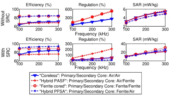
4.5 ANALYSIS OF EFFICIENCY, REGULATION AND SAR ... 109
4.6 MULTIPARAMETRIC ANALYSIS ... 120
4.7 ANALYSIS OF EFFICIENCY AND RELATIVE CURRENT DENSITY ... 130
4.7.1 Evaluating geometry type and size when coils are aligned ... 131
4.7.2 Evaluating stability with misalignment ... 136
4.8 MISALIGNED COILS AT DIFFERENT COIL GAPS ... 142
4.9 CONCLUSIONS ... 143
5 THE POWER ELECTRONIC CIRCUIT ... 149
5.1 INTRODUCTION ... 149
5.2 ELECTRONIC CIRCUITS ... 150
5.2.1 The DC/AC Converter - Inverter ... 151
5.2.2 The AC/DC Converter – Rectifier ... 153
5.2.3 The DC/DC Converter - Regulator ... 153
5.2.3.1 The driver SG3525A PWM ... 154
5.2.3.2 The buck converter ... 156
5.3 BEHAVIOR OF THE BUILT INVERTER ... 158
5.4 BEHAVIOR OF THE BUILT COIL WITH THE RECTIFIER ... 159
5.5 THE COMPLETE SYSTEM WITHOUT REGULATOR ... 163
5.6 THE SYSTEM WITH REGULATOR IN OPEN LOOP ... 165
5.7 CONCLUSIONS ... 168
6 OPTIMIZATION ... 171
6.4 OPTIMIZATION WITH GMSH AND GETDP ... 187
6.5 CONCLUSIONS ... 196
7 FINAL REMARKS ... 199
7.1 SUGGESTION FOR FUTURE ACTIVITIES ... 203
7.2 OTHER ACTIVITIES ... 204
REFERENCES ... 207
APPENDIX A – THE MEDIUM THAT SEPARATES THE PRIMARY FROM THE SECONDARY COIL ... 213
APPENDIX B – TABLES OF THE BIOLOGIC TISSUES DIELETRIC PROPERTIES WITH RESPECT TO THE EXPOSING MAGNETIC WAVE FREQUENCY ... 217
APPENDIX C – SOME BASIC THEORY ... 221
C.1. PROXIMITY AND SKIN EFFECT ... 221
C.2. THE QUALITY FACTOR ... 222
C.3. THE COUPLING FACTOR ... 223
C.3.1. The effect of the coupling factor on the load power and efficiency. ... 224
APPENDIX D – DATA COLLECTION ... 225
APPENDIX E – COMPARISON AMONG THE METHODS ... 227
E.1. COILS WITH THICK WIRES ... 227
E.2. COILS WITH THIN AND THICK WIRES ... 230
1 INTRODUCTION
The researches that aim at the development of devices to support the lives of
patients with circulatory diseases are of great importance since these diseases have
very high mortality rate. There are different clinical applications for circulatory assist
devices such as pre and/or post operation circulatory support, cardiopulmonary
bypass (CPB), Ventricular Assist Devices (VAD) as a bridge for cardiac transplant or
genetic therapy, and Total Artificial Heart (TAH) which replaces the heart completely.
For these reasons, the foundation for research support of the state of Sao Paulo
(FAPESP) approved the thematic project FAPESP 2006/58773-1 that aims to
develop components and subsystems for an implantable centrifugal pump for a
ventricular assist device (FUNDAÇÃO DE AMPARO À PESQUISA DO ESTADO DE
SÃO PAULO, 2007). Different institutions including Sao Paulo University (USP) and
the institute Dante Pazzanese of Cardiology (IDPC) among others are involved in this
thematic project, part of which is the research of this thesis.
In order for these systems to be fully implantable, they require electric power that can
be supplied through the technology of a Transcutaneous Energy Transfer (TET)
system. The biggest advantage of this system is its ability to transfer energy to the
internal devices through the skin without direct electrical connectivity, thus reducing
infections, providing greater comfort and offering greater flexibility to the daily
activities of the patient. This system is being strongly studied in different countries,
using mainly inductive coupling.
Usually, the TET system has one external coil (transmitter) and one internal coil
(receiver), transferring energy like a transformer in which the physical means of
includes the skin. The spacing between the coils (coil gap) depends on the thickness
of the skin of the patient and can vary from 5 to 20 mm, resulting in higher values of
voltage regulation, low coupling and considerable eddy current in the skin with low
system efficiency.
The transmission process is performed by a source consisting of an external battery
which excites an oscillator circuit, generating high-frequency alternating current,
which is applied to the external coil, thus creating a magnetic field. The secondary
system (receiver) contains an internal coil immersed in this time-varying magnetic
field and a rectifier connected to a regulator circuit, which supplies constant voltage
to the VAD and to a rechargeable battery that allows the patient to disconnect from
the external system for part of the time.
Therefore, it is noteworthy that a proper design of this system brings a highly efficient
and robust system that meets the comfort requirements of the patient.
1.1 TARGETS
The primary targets of this research are to study a more reasonable design,
optimization and implementation of methods of energy transmission and create a
safe, compact and reliable TET system that supplies power to artificial organs (AOs)
– more specifically Ventricular Assist Devices, or VADs – with the least possible
discomfort and collateral effect to the patient.
Furthermore, the secondary objectives of this research includes studies that allow the
systematization of an optimal design of the electromagnetic equipment, such as
numerical methods as well as the operation of electronic systems, to convert
1.2 DOCUMENT STRUCTURE
This document is structured in distinct chapters. Each of the following main chapters
contains a brief introduction, a description, and a partial conclusion which may be
used in a posterior chapter.
Chapter 2 shows a basic analysis of the TET system in order to support the
development of the project with some historical highlights. It introduces the
philosophy behind the main principle used to transfer the energy wirelessly,
emphasizing biological aspects such as specific absorption rate (SAR) and induced
current in the biological tissue, as well as their rules and restrictions.
Next, Chapter 3 presents different methods to acquire the properties of the TET coils,
introducing numerical methods such as Finite Element (FE) methods and
measurement procedures. Then, it compares the described methods to decide the
approach to be used along the design of the project.
Subsequently, Chapter 4 makes several analyses with the methodology attained
from Chapter 3, considering physical and virtual prototypes in addition to the use of
ferrite cores and serial resonant capacitors (SRCs). The virtual prototypes allow the
understanding of the TET system behavior with different geometric and electric
construction characteristics. Thus, virtual analyses were performed by varying each
characteristic of the TET system individually and then by varying many
characteristics simultaneously.
Afterward, Chapter 5 makes a brief outline of electronic circuits which are associated
implemented circuits, which are important to define the strategies for the optimization
process.
Observing the need for optimization techniques, Chapter 6 then presents different
optimization strategies and analyses of the behavior of the chosen configurations of
the TET coils.
Lastly, Chapter 7 summarizes the observed remarks and suggests ideas for different
future researches related to this project. It also presents the papers and prizes that
resulted from this research.
Moreover, some appendixes which may clarify some topics in this research were
added to support some readers. They contain:
A. details about the medium between each TET coil;
B. tables with the dielectric properties of some biologic tissues;
C. few basic theories to support the research such as proximity and skin effects, quality factor and its effects on the behavior of the TET system and a deduction of formulas used along the research;
2 TRANSCUTANEOUS ENERGY TRANSFER AND ITS EFFECTS
2.1 INTRODUCTION
This chapter shows a basic analysis of the TET system in order to support the
development of the project. It introduces the philosophy behind the main principle
used to transfer the energy wirelessly and outlines biological aspects such as specific
absorption rate (SAR) and induced current in biological tissue as well as their rules
and restrictions. This chapter also presents some topologies and researches in the
area, which have been studied since the 1970s. And lastly, this chapter uses the
presented concept to conclude some details that should be contemplated during the
design of the TET system.
2.2 TET SYSTEM OVERVIEW
All the studied proposals for TET system development are based on the principle of
inductive link through electromagnetic fields, transferring energy from an external coil
to a coil inside the body, as represented in Figure 2.1.
Figure 2.1 – Basic Diagram of TET system parts.
Thus, the TET system is composed of the following distinguished parts:
1. DC Power Supply outside the body, which could be a battery;
3. Transformer (magnetic transfer device) with the primary coil outside the body to transmit power to a secondary coil inside the body. The coils form a weakly coupled transformer as they usually are not connected by a common ferromagnetic core and they could be misaligned during the movement of the patient. For this reason, in this research, the association of the primary and secondary coils and their respective cores is called transformer;
4. Rectifier inside the body, which converts the AC voltage back to DC so that it can feed an internal battery and power the artificial organ (AO). This rectifier may also be connected to a converter to assure constant DC voltage on the internal battery and the AO;
5. Rechargeable battery inside the body, which is used to energize the AO when the transmitting primary coil is not positioned at the place of transmission;
6. Information Feedback system to convey useful information about the functioning of the internal device to the user. This portion is considered optional since it is not used in many TET systems. But considering that the device is inside the body of a patient, direct access is difficult. Thus, it is important to convey information about the operating condition, among other details.
Given the wide variety of functions of the TET system, its research is quite
comprehensive and can deal with different areas. Furthermore, important aspects to
the patient such as comfort, flexibility, side effects and electromagnetic influences
among other issues should be considered. Thus, one can divide the design of TET
system in the following main stages:
1. Transformer considering heating, efficiency and effects of electromagnetic fields on human being.
2. Electronics for the switching circuit outside the body and the rectifier converter inside the body, considering the efficiency.
The stages are interrelated and depend on information from each other. However, it
is possible to focus only on one specific stage to research. The focus of this thesis is
the research of the transformer, exploring different properties and characteristics in
order to facilitate the creation of a system that works properly under different
conditions with less discomfort to the patient.
2.3 HISTORICAL HIGHLIGHTS
With the introduction of chloroform as an anesthetic agent in the late 1860s,
occasional respiratory and cardiac arrest started occurring during medical
interventions. In 1872, in the United Kingdom, Green used hand-held electrodes
connected to the base of the neck and to the lower left chest of the patient to
intermittently apply the output of a 300 V battery. This action could resuscitate five of
seven cases of cardiac arrest and it was the beginning of the principle of the
defibrillation devices (BRONZINO, 2000).
In 1957, a single myocardial electrode was implanted for the first time in a human
being during a surgery to control ventricular rate and thereafter, such electrodes have
become frequently used during cardiac surgery. Later, in another patient, an
extracorporeal pacemaker was incorporated containing standby techniques, i.e., if a
5 seconds asystole was identified on the ECG monitored patient, the pacemaker was
activated. This type of pacemaker was powered by a wire connected to a domestic
power outlet and the patient could walk only if he pushed the equipment on a small
cart. Then, the quest for portability began (BRONZINO, 2000).
Researchers started thinking about batteries, but several of them were concerned
pacemaker in which the batteries could be recharged through the energy available in
a coil placed on the surface of the chest (BRONZINO, 2000).
In 1960, a group from the University of Missouri-Columbia detailed a theoretical
rationale for a radio-frequency system involving inductive coupling between a thin,
small pancake-shaped coil on the surface of the chest and a similar coil either within
the chest or, alternatively, subcutaneously. Their system had a theoretical transfer
efficiency of about 95 % and was tested only in dogs (SCHUDER, 2002). It
represented the basis to the so called Transcutaneous Energy Transfer (TET)
system.
In 1965, (LOUIS C. WALLER, July 20, 1965) patented a power generator for any
device implanted in the human body as a pacemaker, containing its own internal
power source through which the pacemaker would maintain its normal operation. In
this invention, the patient should use a belt coupled to an element external to the
body that transmits power to an element internal to the body through loops
magnetically coupled and separated by the skin. The coupling between the external
and internal loops is done via a permanent magnet present in the external transmitter
to create a magnetic field which actuates a proximity switch (sensor) on the internal
receiver. This switch closes the circuit indicating that the external device is correctly
positioned with the implanted device and allows the external device to transfer power
only when it is correctly positioned under great coupling conditions.
Considering that the main objective of Waller was to supply power to a pacemaker,
its circuit was intended to generate DC voltage. Thus, the energy transferred by the
alternating loops is rectified and can be replaced by the energy of an internal
rechargeable battery in a way that the pacemaker works even without the external
replaced in case of emergency and this battery can be charged by connecting it to
the power outlet. In this case, the AC energy is rectified to recharge this external
battery and/or power a circuit that has an oscillator that now transforms this energy to
AC with the required frequency to transfer energy through the loops.
Furthermore, this invention has current and voltage meters to indicate respectively
the operability of the external battery and possible fluctuations in the internal load
when the external device is properly positioned with the internal element.
In 1971, Schuder and his group reported the transmission of 1 kW of power for 1 h
between an 11 cm diameter water-cooled coil on the surface and a coil implanted
subcutaneously in a 31 kg dog (SCHUDER; GOLD; STEPHENSON JR., 1971). They
reported that the temperature at the coil tissue interface, as measured just beneath
the internal coil, rose from 36.7 oC to 39.7 oC.
In 1983, (EMPI, Inc. Donald D. Maurer, Oct. 11, 1983) described a TET device that
uses an implanted capacitor whose energy was consumed by the implanted medical
device. As Maurer used TET technology to generate an induced voltage to charge
the capacitor, he thought having an efficient capacitor was more important than
having an efficient TET system and therefore his device had low efficiency. Thus, this
patent is related to a very low voltage level, of the order required for a small
implantable capacitor.
In 1988, (COCHLEAR PTY. LTD University of Melbourne. James M. Harrison; Peter
M. Seligman, May 3, 1988) described a TET system with improved coupling between
the internal and external inductive coils. In order to achieve the coupling
improvements, Harrison added a circuit electrically coupled to the primary coil
the primary coil. His TET system had low power level and therefore had no
applications to supply power to an artificial heart.
In 1994, (UNIVERSITY OF OTTAWA, John A. Miller, Sep. 27, 1994) presented a
simplified TET device increasing the efficiency of energy transfer by 80 %.
Several researchers continued the studies of TET systems considering auxiliary
electronic circuits besides the coils. Some proposed the use of resonant capacitors in
series with the primary and the secondary coils to compensate the inductance as
shown in Figure 2.2, reducing the voltage regulation and decreasing eddy currents
(JOUNG; CHO, 1996; KIM; CHO, 1996).
Figure 2.2 – Circuit showing the induction compensation through resonant capacitors.
(KIM; CHO, 1996)
The researchers also used close-loop driver topologies, incorporating a telemetry
channel and implementing additional control in terms of power management
(PUERS; VANDEVOORDE, 2001).
Most of the researches presented coreless TET coils. These topologies of coils have
the advantage of a more stable energy supply since the self-inductance of the coils
does not change with the variation of the position between the coils. However, such
coils have low energy transmission efficiency due to poor electromagnetic coupling
The use of ferrite cores was also considered by researchers. (MIURA et al., 2006)
proposed new TET coils with thin ferrite cores, which increase the magnetic coupling
factor and self-inductance. They replaced the use of resonant capacitor with a
synchronous rectifier using a digital phase-locked loop (PLL) technique. However,
they reported problems with the heat dissipation capacity. Moreover, continual
fluctuation of electromagnetic coupling between both coils caused a disadvantage of
unstable operation.
Trying to solve the low coupling problem with the coreless TET coils and the unstable
operation problem with the cored TET coils, (OKAMOTO et al., 2009) proposed a
hybrid TET system in which the primary coil was coreless, but the secondary coil had
a ferrite core.
In 2010, Dissanayake presented her PhD thesis in this subject with a flow diagram of
a design methodology for primary and secondary coils, assuring the required
transmission power and maximum temperature on the coils. She used ANSYS to
simulate the system with different coils diameters obtaining the mutual and
self-inductances to compute the maximum transferable power. As soon as she attained
the diameters of the coils able to transfer the desired power, she could specify the
number of turns and type of Litz wire to fit the simulated data. She used this
information in COMSOL software to analyze the temperature on the coils, assuring
that it does not exceed a maximum specified value. As soon as all the requirements
were fulfilled, she obtained the recommended coil design (DISSANAYAKE, 2010). In
her project, she used telemetry to control the frequency in order to make her system
In summary, the first researches on TET systems, more than five decades ago, did
not consider much the effects of the electromagnetic fields in the biologic tissues. But
lately, the study of these effects and of the optimization of the TET systems has
grown intensively for different applications such as artificial hearts, ventricular
assistive devices, and artificial lungs, among others with a wide range of power
requirements.
In Brazil, several institutions such as Dante Pazzanese Institute of Cardiology
(IDPC), the Heart Institute from Hospital of Clinics (INCOR), the University of Sao
Paulo (USP), the Technological Institute of Aeronautics (ITA), and the University of
Campinas (UNICAMP), among other institutions have being working together and
motivating the technology development in this area with financing from CNPq,
CAPES and FAPESP.
In the 90’s, IDPC started the research and development of a model of a centrifugal
pump to support blood circulation, called Spiral Pump. In 1997, Dr. Aron Andrade
worked together with “Baylor College of Medicine” from Houston, Texas, USA to
make an auxiliary artificial heart which used a TET system (ANDRADE, 1998).
Trying to analyze the performance of transmission of energy, Lopes Jr. made a
research at EPUSP in which he built up coreless TET coils based on (SCHUDER;
GOLD; STEPHENSON JR., 1971) with home-made Litz wires that supplied 22 V at
100 kHz to a combination of resistors totaling 20 Ω. During his experiments, he
observed current, voltage and temperature in the coils up to 20 mm distance
2.4 THE TRANSFORMER
2.4.1 Geometry
The coil could have different geometries. However, for the scope of this research,
circular geometries with small differences were analyzed due to the shape of the coil
winding and the fact that sharp corners could hurt the patient and consequently affect
his comfort. Following this premise, the more round the core geometry is, the more
comfortable the TET device is for the patient.
Furthermore, a square coil would add an instability problem to the system in regards
to misalignment. Considering that the central axes of the coil are lined up, a round
core is completely aligned at any rotational position of the cores. In addition, when
the axes are displaced, the TET system behaves similarly at any direction of
displacement due to the symmetry. A square core, on the other hand, has symmetry
only if the relative rotational angle between the cores is a multiple of 90o. Thus, the
behavior of this type of TET system with respect to the displacements between the
coils is different if the coil axes displace in different directions. Besides, even if the
central axes are lined up, a square TET core would change its behavior at any
rotation different than 90o.
In order to clarify the considered TET coils, Figure 2.3 details all the parts of the
Figure 2.3 – Geometric detail of the considered parts of the TET transformer.
Observe that the primary core, external to the body, is surrounded mainly by air while
the secondary core, underneath the skin, is surrounded mainly by fat. As mentioned
in APPENDIX A, the thickness of the skin could vary between 5 and 30 mm, thus the
value of the coil gap (between primary and secondary coils) affects the TET system
design.
During this research, this geometry was used in different configurations considering
ferrite cores or coreless coils. In the case of coreless coils, the region defined by the
cores assumes properties of air and/or fat.
It is also important to remark that the volume described by the area between the
inner and central diameter (the green area) is the space reserved to insert the
winding. In these cases, the simulations were performed considering that the winding
fills this whole space independent of the number of turns and gauge of wire. This
means that the distance between the turns depends on the available space, number
of turns and gauge of wire. For example, with less turns and bigger area, the turns
2.4.2 Equivalent circuit
An ideal inductor would have no losses regardless of the amount of current through
the winding. However, real inductors have winding resistance depending on the
length and cross section of the wire forming the coils. Since the winding resistance
appears as a resistance in series with the inductor, it is often called the series
resistance and it represents the Joule loss effect of the coil.
Thus, one alternative way to model the parameters of the TET transformer is by
using the equivalent circuit model of a regular transformer, a simple circuit composed
of resistive elements (r1 and r2) representing the Joule loss effect of the coils and
other reactive elements (x1, x2 and xm) describing the losses of the magnetic flux, as
shown in Figure 2.4.
Figure 2.4 – Equivalent circuit of a TET transformer.
In Figure 2.4, x1 and x2 depend on the frequency and the primary and secondary
self-inductances, respectively, and xm depends on the frequency, the mutual inductance
and the relation between turns. For frequencies of the order of hundreds of kilohertz,
the capacitive effects could be neglected, but the proximity, skin and eddy currents
effects should be considered (FAIZ; ASHTIANI; BYAT, 1997). The skin and proximity
effects are considered in the values of the frequency dependent parameters r1, r2, x1
and x2. In the case where the coils have magnetic cores, Rp represents the losses in
the core. In case of coreless coils, Rp may be required to represent eddy currents
coreless transformers with relative large wire gauge using an optimization method”1.
This paper was submitted to COMPUMAG 2013 and is currently under review for
posterior publication in the IEEE Transactions on Magnetics. In order to model the
eddy currents, this paper proposes the use of a resistance Rp in parallel with xm
which includes the mutual inductance. In this case, even though coreless coils have
no magnetic losses in the cores, the equivalent circuit of the TET transformer could
be represented by Figure 2.4.
This model is very useful to calculate voltage, current and power with any load
without the need to make a time-consuming simulation or implement a physical
device. Nevertheless, the values of the elements (parameters) must be accurate or
the equivalent circuit model will be unreliable.
2.4.3 Assembly of the TET windings
In this research, the study of the design of TET systems requires the assemblage of
physical prototype coils to evaluate the behavior of the system and validate the
simulations. In most of the studied literature, the primary and secondary windings are
composed of different gauges of Litz wire.
The Litz wire is nothing more than a bunch of copper wire with smaller gauges,
individually insulated and twisted to form a single strand. Each copper wire fills each
position of Litz wire section in a way that the linkage flux and also the current in each
1 This paper can be found at
https://www.conftool.com/compumag2013/index.php?page=browseSessions&form_session=21
wire equalize. Hence, this kind of wire minimizes the AC resistance at high
frequencies, reducing the skin effect.
Although the Litz wire is not a standard product, it is not easy to find. For this reason,
this research used only solid wires instead.
The shape of the coils must also be considered. Zierhofer and Hochmair (1996)
made a geometric analysis to improve the coupling coefficient between two
magnetically coupled coils, showing that the coupling coefficient can be significantly
improved if the windings of the coils are not concentrated in the outer diameter but
distributed along the diameter of the coil forming a planar spiral with only one layer if
possible (ZIERHOFER; HOCHMAIR, 1996).
In addition, they suggested that the outer diameter of the secondary winding should
be smaller than the outer diameter of the primary winding, which reduces the
efficiency but, on the other hand, also reduces the sensitivity to lateral misalignment
while the secondary coil stays within the outer diameter of the primary coil. In this
configuration, the coupling coefficient is constant in relation to lateral misalignment,
but the quality factors of the coils of the transformer at no-load decreases typically by
approximately 20 % due to increased wire lengths. However, Zierhofer and Hochmair
believe that this would not be a big problem because the coils are part of the
transmitter and receiver resonant circuits.
The material that covers the coil also affects its flexibility. There are cases in which
researchers uses polypropylene (CHAN; CHENG; SUTANTO, 2000), but most of the
references use rubber or Silastic. This research is not dedicated to the study of the
best biocompatible material to be used, though this is an important area of research
2.5 SERIAL RESONANT CAPACITORS (SRC)
Knowing the values of the self-inductances of the TET coils, serial resonant
capacitors (SRC) can be calculated to compensate such inductances. Several
researchers used SRC to compensate the leakage inductance, thus its calculation
depends on the mutual inductance too (JOUNG; CHO, 1996).
However, as will be seen in Chapter 3, the mutual inductance depends on the
geometric properties of the coils and consequently changes with the variation of the
displacements and gaps of the coils while the TET device is in use. In the case when
the mutual and therefore the leakage inductances change, a SRC calculated to
compensate the leakage inductance will no longer be accurate for the chosen
frequency. Hence, the frequency must be changed to adjust to the resonance or the
system may not be able to transfer the required power; yet, if the system is able to
transfer the required power, it will be with less efficiency.
Therefore, in this research, the SRC will be calculated to compensate only the
self-inductance (L) at a specific frequency (f):
� = 1
(2.�.�)2.�
(2.1)
2.6 HEATING MECHANISMS
The heating is a very important factor to be considered during the design of the TET
system and may represent a potential problem. For implantable devices with low
power requirement, the rechargeable battery lasts a long time. Therefore, the TET
device recharges the battery for a short time duration (<4 hours) without any
device should be used for longer time. In this case, the generation and dissipation of
heat becomes very important since excessive heating can lead to tissue damage and
discomfort to the patient (LAZZI, 2005).
Many factors could affect the temperature rise during the operation of the TET
device. Some of them include the power losses of implanted components, the heat
radiated from external components, and the rate of dissipation of heat into the
surrounding tissue. Moreover, unpredictable factors such as the ambient temperature
and the external clothing of the patient add a complexity to the estimation of the
temperature since they contribute to the heat dissipation capacity.
Some researchers detailed the analyses of the temperature rise during the use of
bioimplants, considering even the tissue metabolism (LAZZI, 2005). This, however, is
not the focus of this project, though it represents a proposal for future work.
Nevertheless, this research does not ignore the fact that the TET coils may affect the
temperature in the area of contact. Hence, some factors of temperature rise should
be understood.
2.6.1 Heating effects due to dissipated power in the wires
The increase of temperature in the wires is very hard to estimate with accuracy and
requires a more dedicated research due to the large amount of unknown factors that
affect the temperature.
It is known that, the electric current circulating through the wires and electronics with
temperature. The amount of heat released is proportional to the dissipated power,
i.e., the square of the current as given by the law of Joule.
� ∝ �.�2 (2.2)
In this equation, r is the resistance of the winding and I is the net current that cross
the winding.
This released heat amount in the copper windings is related to the heat amount in the
law of heat transfer of Fourier which postulates that the rate of heat transfer is
proportional to the temperature gradient present in a solid.
� ∝ �.�� − ����� (2.3)
In (2.3), θ is the temperature that the system will get to, θref is the ambient
temperature considered as initial temperature and A is the surface of heat exchange,
i.e., it is the surface area of the winding.
Observe that (2.2) and (2.3) are not exact equations and they indicate only
proportionality dependent on an unknown factor. For this reason, in this research, the
increase of temperature is indirectly accounted for by the proportional relation
between the dissipated power and the coil area. For better reading, this project calls
this relation “thermo factor”:
�= �.�
2
� (2.4)
2.6.2 Electromagnetic effects in biological tissues
As previously mentioned, the TET system is based on the electromagnetic field
there is a body part located in the middle of this magnetic field. The question then
arises as whether this could result in a detrimental biological effect, which may be
characterized by some change in a biological system after the introduction of a
specific external stimulus. The electromagnetic waves can generate some kind of
biological effect when the frequency of the electromagnetic wave that transfers
energy is very high. If this frequency is higher than the emission of light, such as
gamma and X-rays (ionizing radiation), the transferred energy would be sufficient to
break chemical connections through ionization, which may damage the genetic
material of the cells, leading to diseases such as cancer for example.
However, unlike gamma and X-rays, the electromagnetic fields with frequencies
lower than the emission of light (non-ionizing radiation) do not have enough energy to
cause the breaking of any chemical bonds, though their direct interaction with the
tissue can result in thermal or non-thermal effects.
The heating is the result of the absorption of the electromagnetic field in a dissipative
medium, where part of the power is reflected by the skin and the other part
penetrates and quickly dissipates with the depth (CRUZ, 2005).
The absorption happens mainly due to the rotation of the dipoles of water and
dissolved ions induced by the electromagnetic field. Therefore, the amount of water
is an important parameter when determining the dielectric properties of the tissue.
The thermal effects have been studied for a long time and, in 1975, Johnson
recommended that all researchers in microwave bioeffects portray their radiation
conditions in terms of an average absorbed energy per unit of mass from an animal
Thus, he described a rate that characterizes the absorption of electromagnetic
energy in animals and depends on the geometry and size of the animal. This rate is
known as SAR (Specific Absorption Rate, W/kg) and is given by:
��� = �.��.��
∗
2.� (2.5)
in which E is the strength of the electric field in biological tissue (V/m); σ is the
electrical conductivity of biological tissue in the irradiation frequency (S/m); and ρ is
the biological tissue density (kg/m3).
Particularly at high frequencies, the conductivity is high since the body has a large
amount of water and its conductivity can be given by the following expression
(BULLA, 2006).
�= 2.�.�.�" (2.6)
In (2.6), f is the frequency in Hz and ε’’ is the permissivity of the biologic tissue.
The average SAR and the distribution of SAR can be calculated and estimated
through experimental measures and their values depend on the following factors:
1. Parameters of the incident field, such as frequency, intensity, polarization and configuration of the source (near or far field);
2. Characteristics of the exposed body, i.e., its size and geometry and dielectric properties of various tissues;
3. Ground effect and reflection of other objects in the field near the exposed body.
As the total energy imposed in an animal can be measured per amount of heat
throughout the body, this factor can also be measured by studying the heat
exchanges or through techniques of balance of power (the absorbed power by the
In addition to the thermal effects of non-ionizing waves, there is evidence that
induced electromagnetic fields have some biochemical or electro physical effects
through direct interaction of oscillatory fields with polar molecules present in the
biological fluids and tissues (BULLA, 2006).
Such effects can stimulate the muscles or nerves due to induced current and thus the
current density J (A/m2) must also be considered (SHIBA et al., 2008).
� =�.� (2.7)
According to (SHIBA et al., 2008), in a TET system, the primary coil current is directly
proportional to the voltage of this coil and inversely proportional to the frequency and
to the mutual inductance between the coils. (SHIBA et al., 2008) concludes that, by
increasing the diameter of the coil, the current density in the skin decreases.
Similarly, SAR depends on the voltage at the primary coil which is inversely
proportional to the mutual inductance between the coils. Thus, a larger diameter coil
reduces the SAR.
Hence, in a first analysis, it is clear that parameters such as frequency, output
voltage, mutual inductance between coils, and diameter of the coils are important
factors for the development of a secure transmission.
2.6.3 Rules and restrictions for the electromagnetism effects
In order to protect all segments of the population against all damages caused by the
identified radio frequency (RF) energy, some international exposure standards have
Available experimental evidences indicate that the exposure of human parts for about
30 minutes at a medium-frequency electromagnetic field, producing a whole body
SAR of 4 W/kg, results in a temperature rise greater than 1 oC. Exposure to higher
intensity fields, producing SAR values greater than 4 W/kg, can overcome the thermo
regulatory capacity of the body and produce levels of body heat even more
dangerous.
Several studies with rodents and primate models have demonstrated the wide range
of tissue damage as a result of temperature rise in excess of 1 to 2 °C of a certain
part of the body (“Local”) or the whole body (“Whole-Body”). The sensitivity to
thermal damage to different types of tissue varies, but the limit for irreversible effects
under normal conditions is greater than 4 W/kg, even for the most sensitive tissues
(INTERNATIONAL COMMISSION ON NON-IONIZING RADIATION PROTECTION,
1998).
Thus, in each country, committees formed by governmental and non-governmental
organizations developed their rules and regulations proposing certain safety limits.
In the United States, the standard C95.1 developed by the IEEE (Institute of
Electrical and Electronics Engineers) was adopted by the North American ANSI
(American National Standard Institute) for the first time in 1966, and it has been
periodically reviewed since. Its last review, in 1999, evaluated over 1400 articles
(DIAS; SIQUEIRA, 2002). The committees that developed the standard consisted of
members from universities, industry and government.
Based on data obtained in the revision of 1982, the IEEE added a safety factor of 10,
placing a limit for the “Whole-Body Average SAR” at 0.4 W/kg and the peak value of
The “Whole-Body Average SAR” is the average value of SAR obtained in the whole
body for a period of 30 minutes. The peak value of the “Local SAR” is the average
value obtained by any SAR in any 1 g of tissue for the same time period.
In 1991, IEEE established a difference between occupational exposure (controlled)
and the general public (uncontrolled), adding greater security for the latter. Therefore,
the “Whole-Body Average SAR” and the peak value of the “Local SAR” for
"uncontrolled" exposure were 0.08 W/kg and 1.6 W/kg, respectively (CRUZ, 2005).
Table 2.1 shows the SAR limits established by the IEEE for a frequency range
between 100 kHz and 6 GHz for a period of 30 minutes.
Table 2.1 – SAR basic restrictions established by IEEE and based on the standard ANSI/IEEE C95.1 for a frequency range between 100 kHz and 6 GHz for a period of 30 minutes.
Characteristic of the
Exposure
Whole-body
Average SAR
(W/kg)
Local SAR
(head and trunk)
(W/Kg/1g)
Local SAR
(members)
(W/kg/10g)
Occupational Exposure 0.4 8 20
General Public 0.08 1.6 4
Similarly, the International Commission on Non-Ionizing Radiation Protection
(ICNIRP), with worldwide acceptance and permission from several other
organizations such as the WHO (World Health Organization) and ILO (International
Labor Organization), set some limits for SAR, current density and power density
according to Table 2.2. These limits provide a wide margin of safety for other
boundary conditions such as high temperature, humidity, and level of physical
Table 2.2 - SAR basic restrictions established by ICNIRP for a frequency range between 100 kHz and 10 GHz for a period of 6 minutes.
Characteristic of the
Exposure
Whole-body
Average SAR
(W/kg)
Local SAR
(head and trunk)
(W/Kg in 10g)
Local SAR
(members)
(W/kg in 10g)
Occupational Exposure 0.4 10 20
General Public 0.08 2 4
The limit for SAR is the same as IEEE C95.1 for the “Whole-Body Average SAR”
exposure, but with only 6 minutes of exposure. For “Local SAR” exposure, the
ICNIRP uses a sample of 10 g rather than 1 g for the IEEE (CRUZ, 2005).
As the measurement of SAR in an animal or human being is very difficult or
imprecise to pursue, some methods that relate the values of accepted SAR inside the
body with measurements performed outside the body were established. For the
microwave range, the external measurements were the power density of equivalent
plane wave whose more usual unit of measure is W/m2 or mW/cm2.
Table 2.3 - ICNIRP basic restrictions for the frequency between 100 kHz and 10 MHz.
Characteristic of the
Exposure
Current Density
(mA/m2) (RMS)
Average SAR
(W/Kg)
Power Density
(W/m2)
Occupational Exposure f/100 0.4 50
In (BRASIL, Lei no 11.934, 2009), the republic presidency signed the law 11,934,
which amended the law 4,771 from September 1965 to make other arrangements on
the limits of human exposure to electric, magnetic and electromagnetic fields in the
frequency range up to 300 GHz in order to ensure protection of the general health
This law adopts the limits recommended by the World Health Organization (WHO),
which recommends the limits of ICNIRP (BRASIL, Lei no 11.934, 2009).
As mentioned, according to ICNIRP rules, a patient that knows the risk of the
exposure to this magnetic field and is oriented to follow the right procedure to
minimize the risks can be exposed at a maximum value of the induced RMS current
density in mA/m2 not exceeding the value of the frequency divided by one hundred,
i.e., Jmax = f 100� .
Therefore, this research works with the concept of relative current density in the skin
in percentage, which is the induced current density divided by its limit at the
frequency of the induction and multiplied by one hundred (J/Jmax.100 %). Since the
acceptable limit by ICNIRP is the frequency divided by 100, the relative current
density is the induced current in mA/m2 divided by the frequency and multiplied by
10000.
2.7 CONCLUSIONS
The difficulty of the design of a TET system is related to the large amount of
parameters that could affect its behavior. The main idea is to attain a TET system
that provides more comfort and reliability to the patient.
In this way, a good alternative would be trying to minimize the volume or weight of
the TET device, taking in consideration the restrictions of the project and all the
unusual situations to which the TET system is submitted.
Thus, the design of the TET system may contain the following restrictions:
2. SAR;
3. Output voltage/power between the required range; 4. Increase of temperature of the wires of the coil.
As mentioned in Section 2.6.1, in this research, the increase of temperature is
indirectly accounted for by the “thermo factor”, i.e., relation of the dissipated power by
the coil area.
Furthermore, since part of the TET system will be positioned in the body of the
patient, it will be subjected to different kinds of coupling situations, such as:
1. Distance between the coils (coil gap): the skin thickness could vary according to the patient;
2. Distance between the axes of the coils (coil misalignment): since the secondary coil is positioned inside the body, the alignment between the coils is very hard to achieve.
Hence, all the mentioned restrictions should be fulfilled in all these coupling
situations. The parameters of the TET system that could help to provide the
requirements of this project (maximum efficiency, minimum volume, low relative
induced current density) could be:
1. Parameters related to the magnetic properties, such as number of turns as well as relative permeability of the ferromagnetic material, inner and outer diameters, and geometry of the cores.
2. Parameters related to the electric system, such as applied voltage and frequency.
2.7.1 Parameters related to the physical properties of the coils
This case considers the primary (L1) and secondary (L2) self-inductances, which
depend on:
• Wire cross section: affects the outer diameter of the coil, thus affecting the inductance. Moreover, the cross section affects the skin and proximity effects, depending on the frequency.
• Relative permeability of the ferromagnetic material of the core.
• The inner and outer diameters of the cores.
In this project, the coil is cylindrical and the turns are uniformly distributed. Otherwise,
the number of parameters would be even higher.
The mutual inductance also depends on the coupling factor k and the relative
position between the coils, what is called disturbance in this project.
The use of ferromagnetic material as the core of the coils also makes the design
process more complex and more susceptible to the aforementioned disturbances
because, in this case, the self-inductance is also affected by the relative position
between the coils, requiring more calculation for reliable results.
2.7.2 Parameters related to the electric system
The electric part of the TET system depends on:
• Applied voltage;
• Frequency;
The voltage and frequency are control parameters to try to fix the disturbances due to
the variation of the relative position between the coils.
Lastly, it is important to cite that the results and conclusions of this chapter were
partially submitted in the following papers to the following conferences and journal:
2. “An accurate model with lumped parameters for coreless transformers with relative large wire gauge”, accepted for poster presentation at EMF 2013 in Bruges, Belgium.
3. “Modeling coreless transformers with relative large wire gauge using an optimization method”, accepted for poster presentation at COMPUMAG 2013 in Budapest, Hungary. The full paper was accepted on October 3rd 2013 for publication in the IEEE Transactions on Magnetics.
3 OBTAINING THE TET COILS PROPERTIES
3.1 INTRODUCTION
This chapter introduces different concepts to compute the lumped parameters of the
TET transformer (self and mutual inductances and joule losses resistances),
including analytic calculations, method of experimental measurements and
simulations through Finite Element Method.
It also discusses different Finite Element approaches, proposing the use of
homogenization techniques to minimize the computational cost of dense meshes
needed for configurations where the penetration depth of the electromagnetic wave
at the specific frequency is smaller than the gauge of the wire.
At the end, it compares the proposed methods with experimental measurements
considering their variation with misalignment and frequency.
3.2 ANALYTIC CALCULATION OF THE INDUCTANCES OF THE CORELESS COILS
In order to simplify the explanation of how to analytically calculate the self and mutual
inductances of a coreless coil, consider first two single-turn coils, i.e. with only one
turn each. The self-inductance of each coil could be calculated, according to
(ZIERHOFER; HOCHMAIR, 1996), by:
�=�0.� ��� �8.�
�� � −2� (3.1)
For a coil composed of N1 concentric circular loops with different inner radii, the
mutual inductance can be calculated as in the situation of multiple loops aligned with
distance d = 0, as will be explained in Section 3.2.4.
The single turn coils could be positioned at three different arrangements as shown in
Figure 3.1 – (a) with the center aligned and coils separated by distance d, (b) with
lateral misalignment ∆, (c) with angular misalignment α.
Figure 3.1 – Position arrangements between primary and secondary coils:
(a) coils aligned and separated by distance d; (b) lateral misalignment ∆; (c) angular misalignment α.
(a) (b) (c)
3.2.1 Turns aligned and separated by distance d.
The mutual inductance of two single-turn coils separated by a distance d with their
centers aligned can be calculated by (see proof in (SOMA; GALBRAITH; WHITE,
1987; ZIERHOFER; HOCHMAIR, 1996)):
�= �0.√�.�.�(�) (3.2)
in which µ0 is the vacuum magnetic permeability 4.π.10-7 H/m, a and b are the inner
diameters of the coils 1 and 2, respectively and
�(�) =�2
� − ��.�(�)−
2
in which K(k) and E(k) are the complete elliptic integrals of the first and second kind,
respectively and
�= � 4.�.�
(�+�)2+�2 (3.4)
3.2.2 Lateral misalignment ∆.
In the cases where there are a misalignment ∆, (SOMA; GALBRAITH; WHITE, 1987)
shows that the mutual inductance can be calculated through the integral
�= �0.�.�
2.� .�
cos�
��.��.�(�).�� (3.5)
in which ϕ is defined in Figure 3.1, G(r) is already defined by (3.3) and
�=� 4.�.��
(�+��)2+�2 (3.6)
�� = ��2+∆2 + 2.∆. cos� (3.7)
��� = ∆. sin�
�+∆. cos� (3.8)
3.2.3 Angular misalignment α.
When the coils are misalignment by an angle α, (SOMA; GALBRAITH; WHITE, 1987)
shows that the mutual inductance can be calculated through the integral
� =�0.√�.�
�√����� �� ���� ���∅�
3
.�(�)�∅
�
0
in which φ is shown in Figure 3.1, G(r) is already defined by (3.3) and
�= � 4.�.�.���∅.����/����
�2+�2+�2−2.�.�.���∅.����+ 2.�.�.���∅.����/���� (3.10)
���= ���∅
���∅.���� (3.11)
3.2.4 Coils with more than one turn.
Since the turns of the spiral coils are circularly concentric, the inner diameter of each
turn increases at least by the wire diameter of the previous turn. Nevertheless, it is
possible to approximately represent this special coil by a set of single-turn coils.
Figure 3.2 shows this approximated model.
Figure 3.2 – Approximated model of the spiral coil.
Thus, in order to consider all the loops of the coils, it is necessary to make the
integration of mutual inductance for each turn:
� =� � ����,��,∆,��
�2
�=1 �1
�=1
(3.12)
Following the same trend of thought, the self-inductance of a coil with more than one