DEmo MOdels Based Automatic worKflow procEss geneRation
Geração de processos automáticos de workflow baseados em modelos
DEMO
Master's thesis in Informatics Engineering
by
Carlos Figueira 30th September 2013
University of Madeira - Competence Center of Exact Sciences and
Engineerings
Madeira Interactive Technologies Institute
Candidate Carlos Alberto da Silva Figueira
Student Number 2055005
Email [email protected]
Thesis Title
DEMO models based automatic workflow process generation
Advisor
Nowadays, more than half of the computer development projects fail to meet the final users' expectations. One of the main causes is insufficient knowledge about the organization of the enterprise to be supported by the respective information system. The DEMO methodology (Design and Engineering Methodology for Organizations) has been proved as a well-defined method to specify, through models and diagrams, the essence of any organization at a high level of abstraction. However, this methodology is platform implementation independent, lacking the possibility of saving and propagating possible changes from the organization models to the implemented software, in a runtime environment. The Universal Enterprise Adaptive Object Model (UEAOM) is a conceptual schema being used as a basis for a wiki system, to allow the modeling of any organization, independent of its implementation, as well as the previously mentioned change propagation in a runtime environment. Based on DEMO and UEAOM, this project aims to develop efficient and standardized methods, to enable an automatic conversion of DEMO Ontological Models, based on UEAOM specification into BPMN (Business Process Model and Notation) models of processes, using clear semantics, without ambiguities, in order to facilitate the creation of processes, almost ready for being executed on workflow systems that support BPMN.
Keywords
Atualmente, mais de metade dos projetos de desenvolvimento de software falham em alcançar as expetativas dos seus utilizadores finais. Uma das causas principais está na falta de conhecimento da organização da empresa para a qual se pretende a construção do sistema. A metodologia DEMO (Design and Engineering Methodology for Organizations) está provada como sendo uma forma eficaz de especificar através da construção de diagramas e modelos, a essência de qualquer organização, a um nível alto de abstração. No entanto, esta metodologia é independente de qualquer plataforma de implementação, falhando na possibilidade de atualização e propagação de possíveis alterações dos modelos da organização para o software implementado, em modo de execução. O Universal Enterprise Adaptive Object Model (UEAOM) é um esquema conceptual usado como base de um sistema baseado em páginas wiki que permitirá modelar uma qualquer organização, independentemente da sua implementação, bem como a já mencionada, propagação de alterações em modo de execução. Com base no DEMO e no UEAOM, pretende-se com a realização deste projeto, desenvolver métodos eficientes e padronizados que possibilitem a conversão automática de Modelos Ontológicos (DEMO) baseados na especificação UEAOM, em modelos de processos na notação BPMN (Business Process Model and Notation) usando-se uma semântica clara e sem ambiguidades, facilitando-se a criação de processos praticamente prontos a executar em sistemas de workflow que suportem BPMN.
Palavras-chave
Acknowledgments are always a tricky part of any long term work due to the fact of, and normally without realizing, forgetting important parts involved, in some cases important parts. For those, who feel and truly know that were an important part of my path along this important phase of my life, I am eternally and truly grateful and you would be aware that without your existence, support and those wise words on the right moments, I would not be at this phase, writing down this words, thinking exactly about you all. You all, were part of this important journey, so that, and to all of you my dear friends, thank you!
This master thesis and its results were possible thanks to my advisor, Professor Doutor David Sardinha Andrade de Aveiro and his support to guide me in the right directions through the entire project. I also thank to University of Madeira and the Madeira Interactive Technologies Institute (M-ITI), which provided the adequate conditions to accomplish the project.
List of Figures...xv
List of Tables... xix
Abbreviations... xxi
Chapter 1 - Introduction... 1
1.1 Motivation... 2
1.2 Problem statement... 3
1.3 Research approach... 4
1.4 Research method... 6
1.5 Report structure... 7
Chapter 2 - Background... 9
2.1 Enterprise Ontology... 9
2.1.1 What is Enterprise Ontology?...9
2.1.2 The PSI-Theory... 10
2.1.3 The Organization Theorem...13
2.1.4 Conclusion... 13
2.2 DEMO Methodology... 14
2.2.1 DEMO meta model...15
2.3 WOSL (World Ontology Specification Language)...16
2.3.1 Stata and Facta...17
2.3.2 WOSL Grammar...18
2.4 BPM (Business Process Management)...20
2.4.1 Introduction to BPM...21
2.4.2 History... 23
2.4.3 BPM life cycle... 23
2.4.4 Conclusion... 24
2.5 BPMN (Business Process Model and Notation)...25
2.5.1 Introduction to BPMN... 25
2.5.2 Structure... 27
2.5.3 Basic Notation 2.0... 28
2.5.4 Conclusion... 36
2.6 UEAOM... 36
2.6.1 Introduction... 36
2.6.2 UEAOM model... 37
xii
2.6.4 Concrete syntax... 40
2.6.5 Simplified core classes... 42
2.6.6 Conclusion... 43
Chapter 3 - BPM Frameworks Comparison... 45
3.1 BPM Frameworks analysis... 45
3.1.1 Comparison criteria... 46
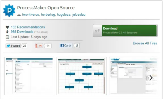
3.1.2 ProcessMaker... 46
3.1.3 jBPM vs Activiti... 49
3.1.4 Bonita Open Solution... 51
3.2 Use Case BPMN Implementation... 53
3.2.1 Case Description...53
3.2.2 BPM framework implementation... 53
3.2.2.1 BOS Implementation... 54
3.2.2.2 Activiti Implementation...55
3.3 Summary... 57
3.3.1 Frameworks comparison according criteria...57
3.3.2 Analysis conclusion...57
Chapter 4 - From DEMO to Workflow...59
4.1 Construction requirements... 59
4.1.1 DEMO models...60
4.1.2 BPMN models... 60
4.2 Acknowledging DEMO models... 61
4.3 DEMO essential conversion information...63
4.4 Conversion rules between models...63
4.5 Conclusion...65
Chapter 5 - Workflow Process Generation...67
5.1 Eu-Rent case description...67
5.2 Applying guidelines... 68
5.3 New DEMO Action Rule Syntax proposal...70
5.4 BPMN generation and implementation example...78
5.5 Conclusion...81
Chapter 6 - Conclusion... 83
6.1 Project results ... 83
6.2 Future work... 84
Bibliography... 85
Appendices...89
Appendix A - Frameworks installation... 91
A.1 ProcessMaker... 91
A.2 Activiti (version 5.11 plus required tools)...97
A.3 BOS (version 5.9.1)...101
1.3 Figure 1: Research approach...4
1.4 Figure 2: Design science research cycles...5
2.1.2 Figure 3: DEMO - Operation axiom... 11
2.1.2 Figure 4: DEMO - Transaction standard pattern...11
2.1.2 Figure 5: The PSI-Theory - Distinction axiom summary...12
2.1.3 Figure 6: Organization theorem representation...13
2.2 Figure 7: The ontological aspect models...14
2.2 Figure 8: DEMO methodology: Diagrams and cross-model tables...15
2.2.1 Figure 9: DEMO Meta-model...16
2.3.2 Figure 10: WOSL grammar - Statum type declaration (Part 1)...18
2.3.2 Figure 11: WOSL grammar - Statum type declaration (Part 2)...19
2.3.2 Figure 12: WOSL grammar - Reference law... 19
2.3.2 Figure 13: WOSL grammar - Dependency law...20
2.3.2 Figure 14: WOSL grammar - Unicity law...20
2.3.2 Figure 15: WOSL grammar - Factum type...20
2.4.2 Figure 16: BPM hype cycle... 23
2.4.4 Figure 17: BPM continuous life cycle... 25
2.5.1 Figure 18: BPMN Development history... 26
2.5.3 Figure 19: Basic BPMN diagram - Flow objects...29
2.5.3 Figure 20: Basic BPMN diagram - Using artifacts... 29
2.5.3 Figure 21: Basic BPMN diagram - Connecting objects...29
2.5.3 Figure 22: Basic BPMN diagram - Collaboration diagram...30
2.5.3 Figure 23: Basic BPMN diagram - Collaboration diagram...30
2.5.3 Figure 24: BPMN Process Semantic - The token game... 30
2.5.3 Figure 25: BPMN Process instances...31
2.5.3 Figure 26: BPMN 2.0 notation - Events categories...31
2.5.3 Figure 27: BPMN 2.0 notation - Types of events...32
2.5.3 Figure 28: BPMN 2.0 notation - Type of activities...33
2.5.3 Figure 29: BPMN 2.0 notation - Gateways...34
2.5.3 Figure 30: BPMN 2.0 notation - Swim-lanes...34
2.5.3 Figure 31: BPMN notation - Process diagram - example 1...35
2.5.3 Figure 32: BPMN notation - Process diagram - example 2...35
2.6.1 Figure 33: TypeSquare with rules... 37
2.6.2 Figure 34: Universal Enterprise Adaptive Object Model... 38
2.6.3 Figure 35: UEAOM - Abstract syntax... 39
2.6.4 Figure 36: UEAOM - Concrete syntax... 41
xvi
3.2.2.1 Figure 38: BPM Implementation on BOS - BPMN model...54
3.2.2.2 Figure 39: BPM Implementation on Activiti - BPMN model...56
5.2 Figure 40: EU-Rent - Action rule 1...69
5.2 Figure 41: EU-Rent - Action rule 2...69
5.2 Figure 42: EU-Rent - Action rule 3...69
5.2 Figure 43: EU-Rent - Action rule 4...69
5.2 Figure 44: EU-Rent - Action rule 5...69
5.2 Figure 45: EU-Rent - Action rule 6...69
5.2 Figure 46: EU-Rent - Action rule 7...70
5.2 Figure 47: EU-Rent - Action rule 8...70
5.2 Figure 48: EU-Rent - Action rule 9...70
5.2 Figure 49: EU-Rent - Action rule 10...70
5.2 Figure 50: EU-Rent - Action rule 11...70
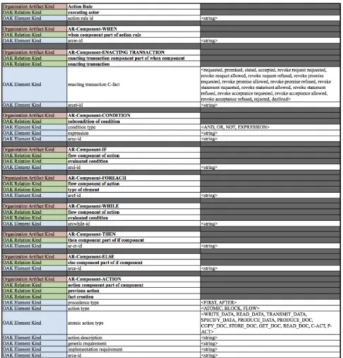
5.3 Figure 51: Action Rule example following the new syntax...71
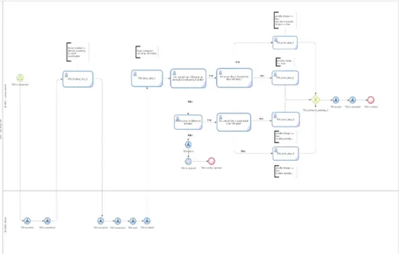
5.3 Figure 52: BPMN diagram for Transaction T04 - car drop-off...72
5.3 Figure 53: UEAOM based Action Rule Meta-Model specification...73
A.1 Figure 54: PM Installation - Select and download...91
A.1 Figure 55: PM Installation - Select the installation language...92
A.1 Figure 56: PM Installation - Start installation...92
A.1 Figure 57: PM Installation - Select installation folder...93
A.1 Figure 58: PM Installation - Additional info...93
A.1 Figure 59: PM Installation - Extract files...94
A.1 Figure 60: PM Installation - Installing files... 94
A.1 Figure 61: PM Installation - Finishing installation... 95
A.1 Figure 62: PM Installation - First time run... 95
A.1 Figure 63: PM Installation - Default user and password...96
A.1 Figure 64: PM Installation - Main dashboard... 96
A.2 Figure 65: Activiti Installation - Designer plug-in...98
A.2 Figure 66: Activiti Installation - Designer plug in - Repository...98
A.2 Figure 67: Activiti Installation - Designer plug in - New project...99
A.2 Figure 68: Activiti Installation - Activiti Explorer - Select version...99
A.2 Figure 69: Activiti Installation - Activiti Explorer - TomCat running 100 A.2 Figure 70: Activiti Installation - Activiti Explorer - Logging in...100
A.3 Figure 71: BOS Installation - Selecting version...101
A.3 Figure 72: BOS Installation - Registration...101
A.3 Figure 73: BOS Installation - Setup installation start...102
A.3 Figure 74: BOS Installation - Selecting installation language...102
A.3 Figure 75: BOS Installation - Selecting JVM to use with BOS...102
A.3 Figure 76: BOS Installation - Setup beginning...103
A.3 Figure 77: BOS Installation - License agreement...103
A.3 Figure 78: BOS Installation - Directory installation...104
A.3 Figure 79: BOS Installation - Retrieve data from others installations 104 A.3 Figure 80: BOS Installation - Installation complete...104
A.3 Figure 81: BOS Installation - BOS initializing...105
A.3 Figure 82: BOS Installation - Main dashboard... 105
B.1 Figure 86: Create BPMN model on BOS - Select the process...108
B.1 Figure 87: Create BPMN model on BOS - Adding forms 1...109
B.1 Figure 88: Create BPMN model on BOS - Adding forms 2...109
B.1 Figure 89: Create BPMN model on BOS - Adding form fields...110
B.1 Figure 90: Create BPMN model on BOS - Run the preview form...110
B.1 Figure 91: Create BPMN model on BOS - Add mysql connection....110
B.1 Figure 92: Create BPMN model on BOS - New mysql connection. . .111
B.1 Figure 93: Create BPMN model on BOS - Add mysql name...111
B.1 Figure 94: Create BPMN model on BOS - Mysql connection...112
B.1 Figure 95: Create BPMN model on BOS - Adding mysql function. . .112
B.1 Figure 96: Create BPMN model on BOS - Connector output...113
B.2 Figure 97: Activiti Modeler - Creating new model...114
B.2 Figure 98: Activiti Modeler - Model workspace...115
B.2 Figure 99: Activiti Modeler - New model...115
B.2 Figure 100: Activiti Modeler - Main dashboard...116
B.2 Figure 101: Activiti Modeler - Creating the model...116
B.2 Figure 102: Activiti Modeler - Edit or delete a model...117
B.2 Figure 103: Activiti Designer plug-in - New project...117
B.2 Figure 104: Activiti Designer plug-in - Creating activiti project...118
B.2 Figure 105: Activiti Designer plug-in - Adding optional references. .118 B.2 Figure 106: Activiti Designer plug-in - Project on package explorer. 119 B.2 Figure 107: Activiti Designer plug-in - Add new BPMN diagram...119
B.2 Figure 108: Activiti Designer plug-in - Save the diagram...120
B.2 Figure 109: Activiti Designer plug-in - Add diagram to the project...120
B.2 Figure 110: Activiti Designer plug-in - Add shapes to the diagram. . .121
B.2 Figure 111: Activiti Designer plug-in - Export BPMN diagram...121
B.2 Figure 112: Activiti Designer plug-in - Deployed files...122
B.2 Figure 113: Importing to Activiti Explorer (Part 1)... 122
B.2 Figure 114: Importing to Activiti Explorer (Part 2)... 123
B.2 Figure 115: Execute model on Activiti - part 1...123
B.2 Figure 116: Execute model on Activiti - part 2...124
B.2 Figure 117: Execute model on Activiti - part 3...124
B.2 Figure 118: Execute model on Activiti - Claiming the tasks...125
B.2 Figure 119: Execute model on Activiti - Input data form - part 1...125
B.2 Figure 120: Execute model on Activiti - Input data form - part 2...125
B.2 Figure 121: Execute model on Activiti - Input data form - part 3...125
B.2 Figure 122: Execute model on Activiti - Input data form - part 4...126
C.1 Figure 123: EU-Rent - Action rule 1 - New syntax...128
C.1 Figure 124: EU-Rent - Action rule 2 - New syntax...129
C.1 Figure 125: EU-Rent - Action rule 3 - New syntax...130
C.1 Figure 126: EU-Rent - Action rule 4 - New syntax...131
C.1 Figure 127: EU-Rent - Action rule 5 - New syntax...132
C.1 Figure 128: EU-Rent - Action rule 6 - New syntax...133
C.1 Figure 129: EU-Rent - Action rule 7 - New syntax...134
C.1 Figure 130: EU-Rent - Action rule 8 - New syntax...135
xviii
C.1 Figure 132: EU-Rent - Action rule 10 - New syntax...137
C.1 Figure 133: EU-Rent - Action rule 11 - New syntax...138
C.2 Figure 134: BPMN model - T01 rental start... 140
C.2 Figure 135: BPMN model - T02 rental end... 141
C.2 Figure 136: BPMN model - T03 car pickup...142
C.2 Figure 137: BPMN model - T04 car drop off...143
C.2 Figure 138: BPMN model - T05 rental payment...144
C.3 Figure 139: EU-Rent - Action rule 1 - UEAOM instantiation...145
C.3 Figure 140: EU-Rent - Action rule 2 - UEAOM instantiation...146
C.3 Figure 141: EU-Rent - Action rule 3 - UEAOM instantiation...147
C.3 Figure 142: EU-Rent - Action rule 4 - UEAOM instantiation...148
C.3 Figure 143: EU-Rent - Action rule 5 - UEAOM instantiation...149
C.3 Figure 144: EU-Rent - Action rule 6 - UEAOM instantiation...149
C.3 Figure 145: EU-Rent - Action rule 7 - UEAOM instantiation...150
C.3 Figure 146: EU-Rent - Action rule 8 - UEAOM instantiation...151
C.3 Figure 147: EU-Rent - Action rule 9 - UEAOM instantiation...152
C.3 Figure 148: EU-Rent - Action rule 10 - UEAOM instantiation...153
2.4.1 Table 1: BPM - Definition terms... 21
3.1.3 Table 2: Main differences between Activiti and jBPM...49
3.1.4 Table 3: Bonita Open Solution Editions Available...52
3.3.1 Table 4: Frameworks comparison criteria... 57
4.2 Table 5: Transaction standard construction pattern... 61
4.2 Table 6: Action rule standard construction pattern...62
5.2 Table 7: Eu-Rent - Transaction result table... 68
5.3 Table 8: Action Rule new syntax proposal... 77
AOM Adaptive Object Model
AM Action Model
BOS Bonita Open Solution
BNF Backus-Naur Form
BPML Business Process Management Language BPM Business Process Management
BPQL Business Process Query Language BPMN Business Process Model and Notation
CM Construction Model
DEMO Design and Engineering Methodology for Organizations
DMM Demo Meta-model
DPM Demo Process Model
GPL Gnu General Public License
JBPM Java Business process management
OMG Object Management Group
PM ProcessMaker
PHP Hypertext Preprocessor
SM State Model
SOA Service-oriented Architecture TRT Transaction Result Table
UEAOM Universal Enterprise Adaptive Object Model XML Extensible Markup Language
WYSIWYG What you see is what you get
CHAPTER 1
Introduction
Within the computer development project communities it is common sense that research and development projects does not end up properly without a well defined plan, good and valid research methods and the right approach to it. It is also true that even with a good plan it is easy to make a possible implementation difficult to understand and transmit to further readers. This seems counterintuitive, however it is plan of this thesis report, to narrow down the gap between a plan, its related development and its consequent implementation.
This thesis report is hoped to be an appropriated plan and an excellent support, to correctly understand the research that take place along this project.
1.1 Motivation
1.1 Motivation
project is in trouble [1].
Based on these studies and their reality, new ways of capturing the essential information about how an organization really work and what they really need, are extremely important to the software development field.
The Organizational Engineering field of study appeared on the nineteens and comes to add new concepts to the way organizations are understood and new ways to analyze their reality, always regardless their implementation.
The DEMO methodology, a well known defined method used to model organizations is the result of the application of the Organizational Engineering field of study. Its application, results in four models: the Construction Model, Process Model, Action Model and the State Model. The major value of these models, besides being easily to understand, are by being independent of the organization final implementation and that, is extremely valuable in terms of what really matters in the way how enterprises are organized. However, and for this particular thesis, was concluded that some implementation details would be relevant and important to be included. Bearing that in mind, was thought as being valuable for this thesis finding a way to include some of those details on the Action Model, more precisely with the creation of the Action Rules1.
The Universal Enterprise Adaptive Object Model (UEAOM) is a conceptual schema being used as the base for the effort to create a wiki-based system that allow an effective enterprise modeling, independently of the language used, so that all the organization changes can be made, saved and propagated in runtime environment in a consistent and coherent way. Having all the DEMO models instantiated on the wiki-system all that information can be gathered and worked out for other type of outputs, as a construction of an automatic workflow process based on the DEMO models and diagrams of an enterprise. The BPMN (Business Process Model and Notation) as a standard notation of the BPM process constructions, is an excellent method to have the DEMO models represented, constructed and finally executed on a workflow system that supports BPMN.
These some news ways of how organizations are viewed and represented by using some well defined methodologies, as DEMO, UEAOM and BPMN opens a new whole of possibilities for even more automated ways of creating processes that work as an excellent support, for even more reliable informations systems, effectively narrowing down the gap that exists between the users' expectations and the final result.
1.2 Problem statement
As time passes the world takes a path of evolution and breath taking discovering that sometimes led to inconsistencies between organizational processes and its information systems. Enterprises get bigger, more complex, globalized and integrated, that they must re-think and re-engineer all their way of working. Organizational processes became huge and complex, with more people involved and even bigger cooperation between them in sensible decisions that must be traceable and in constant updating. Flexibility and constant interoperability are nowadays crucial facts to maintain organizations in the right path. In order to do that, since the first use of a technology system, methodologies were used and today even more.
DEMO as a result of the Organizational Engineering field of study has been a growing methodology for the past few years that have been proving along the way to be a well defined and a trustworthy method to model the essence of enterprises, on a high level of abstraction, independent from its real implementation, distinguishing the business, informational and documental actions. From the DEMO application, results four related aspect models: The Construction Model, which represents the organizational construction, the Process Model, that represents the inter-related within and between the organizational transactions, the Action Model, that have all the action rules related to each transaction and its actors and the State Model, that represents the possible states of the production world and the coordination world of an enterprise [5]. Even though and despite the advantages of using DEMO, it lacks on the possibility of a direct implementation of its concise results. DEMO is made to be read and easily understood by humans so it can not be technically and directly implemented by an information system without something in between.
The UEAOM (Universal Enterprise Adaptive Object Model) is an effort to construct a wiki-based system that will gather all the models and diagrams, result of the appliance of the DEMO methodology in wiki-pages, easily editable and updatable.
BPMN is a standard and a well known notation of the Business Process Management methods. Both DEMO and BPM methods are well defined and it certain adds major value to any organization and even more with the combination of both methods.
1.3 Research approach
1.3 Research approach
The main research idea is based on what is depicted on Figure 1. The first step is about acknowledging BPM frameworks.This step happens in a moment
where the main goal proposed for this project was the creation of a capable parser to directly convert an UEAOM DEMO model based of an organization into an executable BPMN process, so that a thorough analysis within the BPM
frameworks was due.
After step 1, follows the acknowledgment of DEMO models and how they are constructed. This step is extremely important since it is based on the DEMO models that the final BPMN process is constructed. A full understanding of the DEMO construction works as a solid preparation for the following research. After accomplishing the previous step, the UEAOM model principles and also its construction details are acknowledged. The DEMO models are represented on this model, so it is a concept that needs to be very clear.
Knowing how DEMO models are constructed it is necessary to understand which are the diagrams that have the essential information to be gathered in order to have the necessary information for the conversion. That part is seen on step 4. Since both, DEMO and BPMN models are conceptually different even in its constructions, how are they going to be compliant? In step 5 were found the conversion rules to make both models compliant.
Steps 5, 6, 7 and 8, work as an iteration cycle. Starts with having the generation guide worked out, then with the instantiation requirements for the guidelines created on the previous step and finally with the BPMN construction. Then the BPMN model is tested in order to check if the models are compliant. The final step is to have a BPMN workflow model compliant with the organization DEMO models.
1.4 Research method
According to A. R. Hevner [6] [7], Design Science Research – the Information Systems Research paradigm that was adopted on the evolving work that took
place in this project – should be seen as a group of three closely related cycles of activities. These activities are depicted on Figure 2. Hevner claims that the individual application of these three activities in an isolated way does not constitute a good design science research. Only the conjunction of the three can actually render good design science research with a valid output. In this thesis, and regarding the relevance cycle depicted on Figure 2, was identified a
Figure 2: Design science research cycles
1.4 Research method
clear problem of ambiguity and lack of concise and essential information on current DEMO's action rule syntax – detailed later on Sub-chapter 5.3-New DEMO Action Rule Syntax proposal - so an opportunity to reach a new more solid and concise syntax was at hand. Regarding the Rigor cycle, this project was supported by all the theoretical foundations grounding on DEMO as well as the UEAOM patterns. The most important cycle is the Design cycle itself, out of which resulted the proposal2 presented on this thesis of a new meta-model for DEMO's Action Model. An exhaustive and thorough evaluation was made with many iterations of the cycle where new elements would be added to DEMO's Action Meta Model and instantiated on the new syntax within the EU-rent3 case and verifying if it allowed to specify maximum ontological information in a concise and comprehensive way, normally not the case in DEMO's Action Model. While instantiating and increasing the complexity of EU-rent case's action rules to a more realistic level, sometimes was found that some concept in the meta-model should be unary, some other times other concepts should be binary, and at other times was found that would need to specify new concepts at meta-level like atomic action and flow.
The final proposal presented is the result of a long and thorough process of conceptual evolution and comprehensive instantiation, thus following the tenets of Design Science Research.
1.5 Report structure
Chapter 1, is dedicated to give an insight about this thesis research problem and suggested solution. In Chapter 2, is shown and explained the most important foundations and useful background information about Enterprise Ontology, the PSI-Theory and the Organization Theorem. DEMO methodology is also acknowledged along with the WOSL (World Ontology Specification Language), a specification language proposed by Dietz [8]. The BPM fundamentals and its standard notation - BPMN - is introduced and described. The UEAOM is also reason of attention in this chapter, acknowledging its main foundations, principles and its way of being an important asset for this project.
Is in Chapter 3 where a thorough research and comparison among BPM frameworks is made. One of them is chosen in order to construct and evaluate the final solution model. Implementation examples in each of the frameworks and a final conclusion are described.
Chapter 4 contains the main work of this research. From DEMO to Workflow, describes the necessary requirements from both DEMO and BPMN models, the generation guidelines, how to capture the essential information from
DEMO models and the necessary conversion rules to make both models compliant.
CHAPTER 2
Background
In this chapter and without much further deepen on the primordial subject of this thesis, is appropriated to give an insight and enough foundations about the subjects that are used and discussed on this graduation thesis so that the reader can easily focus his mind and effort on the right related subject.
2.1 Enterprise Ontology
Enterprise Ontology is a relatively new theme. Being recent for the most of the ones related to computer technologies, it is important that its definition should be simple, clear and easily understandable.
This novel theme is important for this work since it is based on it that some implementation and important decisions are based on. Before its complete definition there is first a relatively simple question that deserves an answer: what means Ontology? The definition adopted in this work is based on the computer technology related philosophy [9]. Ontology is a combination of two greek words: onto and logia. Onto stands for “being: that, which is” and logia for “science, study, theory” [10].
Having that in mind, being in this particular case would be the enterprise and combined with study, results in the in deep study of an enterprise. Further details are made in the next paragraphs.
2.1.1 What is Enterprise Ontology?
2.1 Enterprise Ontology
explicit specification of a shared conceptualization among a community of people of an enterprise (or part of it)”.
The full essence of the operation of an organization is what Enterprise Ontology is all about. This means that Enterprise Ontology is totally independent from the current realizations and implementation of the organization [12].
According to Dietz [11], the theory that underlies the notion of Enterprise Ontology is called the PSI-Theory. PSI-theory stands for Performance in Social Interaction. This theory is used by Dietz to construct a methodology which provides an ontological model of an organization, a model that should meet five quality requirements: the needed to be coherent, comprehensive, consistent, and concise and that only shows the essence of the operation of an enterprise model [11].
Based on [11], coherent it means that the distinguished aspect models constitute a logical and truly integral whole. By comprehensive it means that all relevant issues are covered. By consistent it means that all the aspect models are free from inconsistency. By concise it means that no superfluous issues are regarded in it, that the whole model is compact and succinct. And for the most important matter, is that this model should be essential, that only shows the essence of the enterprise, its deepen and its insight structure [11]. This referred methodology is called the Design and Engineering Methodology for Organizations, (DEMO) and is defined on Sub-chapter 2.2.
Why Enterprise Ontology?
The ontological model of an enterprise offers a reduction of complexity of over 90% [11]. This reduction of complexity is welcomed and turns any organization totally manageable and transparent for its manager. With that, it also shows the coherence between all the fields of the enterprise, such as business processes and the organization structure [12].
2.1.2 The PSI-Theory
The theory that supports the notion of Enterprise Ontology is the PSI-Theory and its ultimate goal is to capture the full essence of an organization. For that, four axioms were created [11].
Operation Axiom
The first axiom is called the Operation Axiom and states that Subjects in one organization normally perform two kinds of acts: production acts and coordination acts. The subject responsible for performing those acts is the actor and being responsible for that turns him the performer of a certain actor role [11].
creation of goods and services for the organization. As a result for performing P-acts there is the creation of production-facts (P-facts for short) that could be something that has been manufactured (material) or something that has been done or decided (immaterial) [12].
By performing coordination-acts (C-acts for short) the subjects enter into and comply with the commitments regarding the production-acts. A C-act is performed by one actor, the performer, and directed to another actor, the addressee. C-acts are intentions (request, promise, question, etc). The result of a C-act is a coordination fact (C-fact for short) [12].
Transaction Axiom
The second axiom is the Transaction Axiom and states that both coordination and production acts are performed as steps in universal sociological patterns called transactions. The axiom shows that this patterns of coordination are the same for all type of organization. Figure 4 shows the transaction standard pattern.
In one transaction two actors are involved, the initiator and the executor. One transaction is composed by 3 phases. The Order-Phase (O-Phase) the Execution Phase (E-Phases) and the Result-Phase (R-Phase). In the O-Phase is where the initiator and the executor of the transaction tries to reach an
Figure 3: DEMO - Operation axiom
Source: Adapted from [11]
Figure 4: DEMO - Transaction standard pattern
2.1 Enterprise Ontology
agreement about the intended result of the transaction. In the E-Phase is where the P-Fact agreed upon the O-Phase came to execution.
A transaction ends with the R-Phase, where the initiator and the executor work to reach an understanding about the P-Fact produced on the execution phase. The initiator can either reject or accept the result.
Composition Axiom
The composition axiom describes how the P-Facts are interrelated. It also states that every transaction is enclosed in some other transaction or it is a costumer transaction or it is a self activation transaction. According to Dietz this axiom is a well-founded definition for the notion of business process [11]. According to [11]:
A business process is a collection of causally related transaction types, such that the starting step of either a request performed by an actor role in the environment (external activation) or a request by an internal actor role to itself (self-activation).
Distinction Axiom
The distinction axiom that can be seen on Figure 5 states that exists three basic human abilities performed by the transaction actors: performa, informa and forma. It is because of this axiom that a substantial reduction of complexity on both coordination and production of an organization is achieved [12].
The forma ability is related with the form aspects of communication and information [12].
The informa ability concerns the content aspects of communication and information [12].
Figure 5: The PSI-Theory - Distinction axiom summary
The performa ability is about bringing out the new and original things, directly or indirectly by communication [12].
2.1.3 The Organization Theorem
The organization theorem - Figure 6 - combines the advantages of the four previous depicted axioms into one concise, comprehensive, coherent and consistent notion of an enterprise [12]. The organization theorem states that the organization of an enterprise is a heterogeneous system that is constituted as the layered integration of three homogeneous systems: B-organization
(Business organization), the I-organization (Intellect) and the D-organization (Document) [12]. These three systems are called the aspect systems of the total organization [12] and can be seen on Figure 6.
2.1.4 Conclusion
This chapter was used to give a fully insight about enterprise ontology and its primary goals. In the PSI-Theory section, was described the four axioms of enterprise ontology and as stated its major goal, that is extract from each of the axioms, the full essence of an organization from its actual appearance.
The organization theorem is intended to combine the benefits of each of the four axioms into one concise, comprehensive, coherent and consistent notion of an enterprise.
With this, is fair to acknowledge that the enterprise ontology described by Dietz describes a very well-founded and defined theory about enterprises.
Figure 6: Organization theorem representation
2.2 DEMO Methodology
2.2 DEMO Methodology
The DEMO methodology is based on the PSI-Theory of Enterprise Ontology that was previously explained and describes a set of models and diagrams to model an organization.
According to [13] and after a ten year study executing 28 projects, DEMO has been declared as an excellent methodology for the (re)-design of organizations. With that, it became to be widely accepted in both scientific research and practical appliance [12]. Being more specific, the DEMO methodology provides a method to represent the full essence of an enterprise on an ontological level.
The essential information of the enterprise being modeled is visualized in a set
of models and each model represent different aspects of the enterprise.
The referred models are: Construction Model (CM), Process Model (PM), Action Model (AM) and the State Model (SM) and they are constructed correlated with each other representing coherent information in a platform independent way [5].
The CM specifies the construction of the organization and its transaction types. It also states the actor roles and the transactions between them, the information links between the actor roles and the information banks [11]. Due to activeness and the passiveness of the influence between actor roles the CM is divided into the Interaction Model (IAM) and the Intersection Model (ISM). The IAM is where the active influences between actors are shown with the initiator and the executor. ISM contains the internal and external information banks and also
Figure 7: The ontological aspect models
the information links between the actor roles and the information banks [11]. The PM contains, for every transaction in CM a specific transaction pattern and their causal and conditional relationships between transactions [11].
AM is the rule base that serves as guidelines for the actors actions. The action rules are composed by all the information from the previous models, CM, PM and SM, meaning that all the information about enterprises business is covered in this model, being one of the most important models on the methodology [11].
The State Model (SM) specifies the object classes, fact types, result types and the ontological coexistence rules [11].
All the previous depicted models constitute an essential representation of an enterprise in the business domain. With this, is fair to admit that DEMO is a well-defined methodology that is extremely useful on nowadays enterprise representation.
2.2.1 DEMO meta model
The DEMO meta model is in simple words the skeleton of the DEMO models and specifies the construction and the relationship between them (CM, PM, AM and SM) and can be seen on Figure 9. To represent the DEMO meta-model, is used the WOSL4 (World Ontology Specification Language) specification language. The meta model is considered as a big State Model.
4 WOSL is specified in Sub-chapter 2.3-WOSL (World Ontology Specification Language) and further information is found on Chapter 5 of [8].
Figure 8: DEMO methodology: Diagrams and cross-model tables
2.3 WOSL (World Ontology Specification Language)
2.3 WOSL (World Ontology Specification Language)
WOSL is a specification language presented by Jean L.G Dietz and is used to specify world ontologies. A world ontology is based on the specification of the state space and the transition space of that specific world. The state space
Figure 9: DEMO Meta-model
means the set of allowed or lawful states. It is specified by means of the state base and the existence laws. The set of statum types of which instances can exist in a state of the world are specified by the state base. The inclusion or exclusion of the coexistence of stata are determined by the existence laws. The transition space means the set of allowed or lawful sequences of transitions. It is specified by the transition base and the occurrence laws. The set of factum types of which instances may occur in the world are specified by the transition base. Each instance has a time stamp which is the event time.
The WOSL specification language is important for this work since it is the language used to specify the UEAOM5 (Universal Enterprise Adaptive Object Model) and some of the models used on the DEMO methodology.
2.3.1 Stata and Facta
A world can be at any moment in a particular state, which is defined as a set of objects. These, are said to be current objects during the time that the state at that particular time prevails. A state change is called a transition. The occurrence of a transition is called an event. By consequence, a transition can happen several times during the lifetime of a specific world, instead of events that are unique. An event is caused by an act. In order to understand profoundly what a state of a world is, and what a state transition is, it is necessary to distinguish between two kinds of objects, which we are called stata (singular: statum) and facta (singular: factum).
A statum is something that is just the case and that will always be the case; it is constant. Example: The author of book title T is A. The existence of this particular objects are timeless. A derived statum is defined by its derivation rule. The being specified of this rule is the only necessary and sufficient condition for the existence of the derived statum. This marks an important difference between a world and a database system about that world. E.g. the age of a person in some world exists at any moment, however, it has to be computed when it is needed. Stata are subject to existence laws. These laws require or prohibit the coexistence of stata. For example, if the author of some book is “Ludwig Wittgenstein”, it cannot also be “John Irving”.
A factum is the result or the effect of an act. Example: book title T has been published. The becoming existent of a factum is a transition. Before the occurrence of the transition, it did not exist and after the occurrence it does exist. Facta are subject to occurrence laws. These laws allow or prohibit sequences of transitions. For example, sometime after the creation of the factum “loan L has been started”, the transition “loan L has been ended” might occur, and in between several other facta may have been created, like “the fine for loan L has been paid”.
2.3 WOSL (World Ontology Specification Language)
2.3.2 WOSL Grammar
In order to keep the specification of the grammar of WOSL orderly and concise, it is presented in a number of figures.
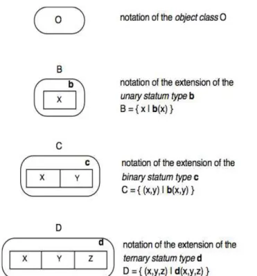
Figures 10 and 11 depicts the way in which statum types can be specified. By the declaration of a statum type is understood stating that the statum type belongs to the state base of the world under consideration. Statum types can be declared intensionally or extensionally. By intensional we mean the notation of the statum type as a unary, binary, ternary etc. concept type. Intensional notations are referred to be a bold small letter (or a string of small letters). Extensional notations are referred to by a capital letter (or a string of capital letters). To understand what a state of a world is, it is necessary to distinguish between two kinds of objects: stata and facta. WOSL language has several graphical pictures to represent these stata and facta.
Figure 10: WOSL grammar - Statum type declaration (Part 1)
Figure 12 shows an example of a reference law. Figure 13 shows a dependency law.
Figure 14 shows an unicity law.
Figure 11: WOSL grammar - Statum type declaration (Part 2)
Source: Adapted from [11]
Figure 12: WOSL grammar - Reference law
2.3 WOSL (World Ontology Specification Language)
Figure 15 shows an example of a factum type.
2.4 BPM (Business Process Management)
In the business world domain, BPM acronym can be easily confused with other different expansions that are somehow related, as Business Process Modeling, Business Process Model and so on. Despite that, the most generic is BPM for Business Process Management and is the one that is focused in this chapter definition.
Business Process Management is, as said above, the most generic definition and refers to all the activities used to control the enterprise management. This chapter is aim to describe BPM and its most important related activities.
Figure 13: WOSL grammar - Dependency law
Source: Adapted from [11]
Figure 14: WOSL grammar - Unicity law
Source: Adapted from [11]
Figure 15: WOSL grammar - Factum type
2.4.1 Introduction to BPM
What is Business Process Management?
After so many years having in mind that BPM (Business Process Management) exists there is not yet a most correct and true answer to this question. It seemed important to clarify this because there is not a universal truth about it. For this thesis was adopted the definition that seemed the most appropriated and reasonable for the sake of this project according some of the most quoted publications regarding that matter.
Based on [14] Business Process Management is the discipline that describes structured methods and techniques used to make a business process more efficient adaptive and effective for accomplishing a specific task within an organization. BPM techniques and methods also permits the identification and modification of existing processes in order to align them to future possibilities of change.
BPM could also be seen as the responsible for narrowing down the gap between the line of business and the IT department. According to a recent research based on [14], has been concluded that cooperation and coordination between this two normally separated departments, is quite important and very useful for a more valid and complete BPM.
Keep in mind that BPM is not a tool of software or even related with technology. However, it can involve technology and if used in the right circumstances and with valid justification could be a useful help to achieve efficiency on process-modeling organizations, which is what BPM is intended for. For instance, the use of process-modeling tools are extremely important since it will be difficult to complete complex process-modeling improvements without such tools [15].
Other word of precaution for organizations is they should be aware that BPM tools itself are just a piece of software and can do nothing related with business process improvements without the knowledge and the right methodologies. Summing up and based on [15] that suggests that BPM is:
The achievement of an organization's objectives through the improvement, management and control of essential business processes.
Table 1:BPM Definition terms, shows its details:
Table 1: BPM - Definition terms
Source: Adapted from [2]
2.4 BPM (Business Process Management)
about realizing the value or business benefits as outlined in the project business case.
Organization The organization in this context refers to an enterprise or parts of an enterprise, perhaps a business unit that is
discrete in its own right. It is the end-to-end business processes associated with this part of an organization. This end-to-end focus will ensure that a silo approach
does not develop.
Objectives The objectives of a BPM implementation range from the strategic goals of the organization through to the
individual process goals. It is about achieving the business outcomes or objectives. BPM is not an objective in itself, but rather a means to achieving an
objective. It is not a solution looking for a problem.
Improvement Improvement is about making the business processes more efficient and effective.
Management Management refers to the process and people performance measurement and management. It is about
organizing all the essential components and subcomponents for the processes. Arranging the people, their skills, motivation, performance measures, rewards, the processes themselves and the structure and
systems necessary to support a process.
Control BPM is about managing the end-to-end business processes and involves the full cycle of plan–do– check–act [16]. An essential component of control is to
have the ability to measure correctly. If something cannot be measured, it can't be controlled and
managed.
Essential Not every process in an organization contributes towards the achievement of the organization’s strategic
objectives. Essential processes are the ones that do.
Business An implementation of BPM must have an impact on the business by delivering benefits. It should focus on
the core business processes that are essential to the primary business activity – those processes that contribute towards the achievement of the strategic
objectives of the organization.
that: “a true process comprises all the things we do to provide someone who cares with what they expect to receive.” [17]This covers a true end-to-end process, from the original trigger for the process to the ultimate
stakeholder satisfaction. Burlton adds that the “ final test of a process’s completeness is whether the process
delivers a clear product or service to an external stakeholder or another internal process”.
2.4.2 History
As everything in computer technologies related, BPM had ups and downs and a really tough road until it became the “next big thing” in business process related [15]. It stood out and continued from then, thanks to others various failed attempts for achieving the process-based organizational efficiency.
Adapted from [15], Figure 16: BPM hype cycle, shows the last two decades of how the process cycle has progressed.
2.4.3 BPM life cycle
As seen above, BPM consists on techniques and methodologies of optimizing business processes profitability and efficiency. For that, there are many possibly approaches depending on who is implementing it or even what kind of result is expected for the process.
On this thesis was used and studied the simplest, however it is a very complete approach, so it is easily understood with all the necessary details.
Figure 16: BPM hype cycle
2.4 BPM (Business Process Management)
The worth knowing approach is based on [18] and consists in five major phases: Model, Automate, Manage/Execute, Monitor and Optimize. In the next few paragraphs all of this phases are described in further detail.
Model
Such as much everything that is based on various phases - computer related - it must have a primary model, like a skeleton that is wrapped and perfected on the following phases. The first step is simple but at the same time extremely important. Is based on this model that the others phases rely on.
In this phase a high-level diagram of the process is created with the goal of gathering just enough information to understand conceptually how the process works, and which are the steps involved in it, without being mislead by its implementation details [18].
Automate
During this phase and based on the previous, the model is expanded in order to create a specific set of instructions and rules needed to run the process. At this point all the decisions regarding the details of how the implementation should be made, are done [18].
Execute/Manage
Execute phase is within the manage phase since it is totally related. It is the way that the manage of the process is made, by executing it.
The execution phase is basically to interpret the instructions created on the Automate phase, to manage the flow of the process since its beginning until its completion. After that and with the BPM software tool the workflow engine is responsible for creating tasks and automatically directing them to the right people or systems based on the process rules [18].
Monitor
The monitor phase is where process performance is measured, tracked and reviewed for potential and possible improvements [18].
Optimize
Optimize phase is used by managers to - regarding all the information learned from the manage phase - optimize the process. Things as enhancing the data collection forms, adding or removing tasks, automating tasks that were made manually are made in this phase. The ultimate goal of this phase is to identify changes that will certainly improve the all process [18].
2.4.4 Conclusion
process modeling on organizations, is easy to understand that it has lots of benefits. It is not a software tool that solve all issues process related but will certainly help if used with knowledge and with the right amount of technology. Worth saying that, and maybe one of the most ignored aspect of BPM, is its continuous improvement. As an organization change, with it processes and environment changes, along with technologies. Also with that, processes need to change in order to meet the actual needs.
The five steps of business process management can be considered as part of a continuous life cycle. Once a potentially change is identified, the cycle of implementation begin all over again and again until the changes are successfully made. Having all this in mind the organization willing to implement BPM methodologies and techniques makes a continual and incremental improvement to its business processes [18].
2.5 BPMN (Business Process Model and Notation)
BPMN, stands for Business Process Model and Notation. What is BPMN, its history of development and its actual notation is what is shown in the next sub-chapters.
2.5.1 Introduction to BPMN What is it?
BPMN is basically a method to graphically represent the steps of a business process in a business process model in a form of diagram. However being different in context it is very similar to a flowchart. The notation of BPMN was specifically designed for coordinate the sequence of the processes and the
Figure 17: BPM continuous life cycle
2.5 BPMN (Business Process Model and Notation)
way that messages flow between activities, processes and participants. Flowchart vs Modeling
Even being very similar there are some differences that deserves some concerning.
A flowchart, and based in [19], is “A graphical representation of the sequence of activities, steps, and decision points that occur in a particular, discrete process”. A flowchart is mainly used to explain the sequence of a process graphically, to improve communication and obtain business-user validation, to identify bottlenecks and loops, to assist with problem analysis, to provide a blueprint to development and to identify the variations in process activity [19]. The modeling process extends the flowchart for things that cannot be enumerated on the basic flowchart: as mapping dependencies and related flows, adding data intelligence to the steps, enabling simulation of flows to check for efficiencies and bottlenecks, enabling reuse of mapped chart elements and finally supporting future monitoring of improved processes. Why it is important?
Over the past few years the world of business processes for organizations has dramatically changed. The organizations demanding for more complex processes has increased and with that a necessary reformulation of how the business processes should be made was necessary. Even a medium sized organization that happen to use the IT's to its normal daily work makes use of coordination between participants and that could became quite complex if not treated well enough. Until then and without BPMN there wasn't a standard modeling technique to avoid this kind of complexity so that BPMN has been developed to provide users with a global and free notation.
Development history
Bringing up some history, all began on the beginning of 20th century, when the
Figure 18: BPMN Development history
BPMI (Business Process Management Initiative) started to develop the BPML, which stands for Business Process Management Language. BPML is an Extensible Markup Language as a mean of modeling business processes. Along with BPML, appeared the BPQL (Business Process Query Language), developed by Initiative members as a standard management interface for deployment and execution of defined business processes. Both BPMN and BPQL were open specifications and the first draft of BPML was submitted in August 2000 and made available in March 2001. Was BPMI intention to proceed on the next few years the development of both specifications.
However in 2004, BPMI merged with OMG (Object Management Group) and since then both worked on the creation of BPMN. The actual version of BPMN is the version launched in August 2009 as BPMN 2.0 Beta 1, today it stills by BPMN version 2.0.
OMG is an international non-profit organization and open membership, that was founded by a partnership between some well-known companies back then, in the late's 1980, more precisely in the year 1989. With a motto of “We deliver the standard” is quite straightforward what they intended to do with the creation of such organization. Their focus was about the modeling of programs, systems and businesses processes standardization. Since they only provide specification, all the implementation should be based on the same specification, so all the business related implementations could be made having the same guidelines leading to a final similar, understandable implementation [20].
Main goal
The main goal of BPMN is essentially to support BPM (Business Process Management) by providing the ability to both technical and business users to easily understand the provided notation. It could also represent extremely complex process semantics and even still be quite easy to understand.
2.5.2 Structure
BPMN gives the ability to model three different, but very similar, aspects of any business process. The Process itself, the Collaboration, and the Choreography. This three different aspects of any organization can be represented on different types of diagrams.
The process is seen as a sequence of activities and events related to a business process.
The collaboration is basically a process that has two or more participants that exchange messages between each other. The major importance of a collaboration diagram is essentially the sequencing of the activities the events and the messages that are traded between the participants [21].
2.5 BPMN (Business Process Model and Notation)
type of representation was only introduced on BPMN version 2.0 and is still not used very often.
2.5.3 Basic Notation 2.0
Based on [21], a business process is defined as simple as: “A sequence of activities performed by one or more business participants in order to deliver value to he business”.
BPMN models have their own notation composed by a set of graphical elements used to construct its own diagrams. Essentially, a process is defined by a set of elements that compose different types of flow nodes that could be connected by sequence flows, in order to form a kind of flowchart [21].
All the notation described in the next paragraphs are based on the BPMN version 2.0.
The process diagram
BPMN have four simple basic elements categories for the construction of its diagrams [21]:
• Flow Objects are composed by events, activities and gateways.
–Events is what happens during the process;
–Activities are worked performed in the process;
–Gateways control the flow along the the process.
• Connecting Objects are composed by sequence flow, message flow and associations.
–Sequence flows are according the flow of the activities;
–Message flows are messages between process participants;
–Associations associate text or data to the modeling elements.
• Swim lanes are composed by pools and lanes.
–Pools represent a participant in the process;
–Lanes represent a group of related activities.
• Artifacts are composed by data objects, groups and annotations.
–Data objects show to the user which data is required or produced in one specific activity;
–Group is simply used to group related but different activities so it became more understandable for the context in which is related but does not affect in any way the flow of the diagram;
Figures 19, 20, 21, 22 and 23 illustrates some examples of BPMN
constructions and notation used to construct its respective processes.
Figure 20: Basic BPMN diagram - Using artifacts
Source:[21]
Figure 21: Basic BPMN diagram - Connecting objects
Source:[21]
Figure 19: Basic BPMN diagram - Flow objects
2.5 BPMN (Business Process Model and Notation)
Process Semantics
The so called token game is basically an imaginary focus to control the flowing of the process. The token runs the entire process via the sequence flow of the diagram [21].
Figure 24: BPMN Process Semantic - The token game
Source:[21]
Figure 22: Basic BPMN diagram - Collaboration diagram
Source:[21]
Figure 23: Basic BPMN diagram - Collaboration diagram
Process instances
One process may have one or more instances of its implementation. This means that could exist for the same process diagram various running instances at the same time.
Events
An event in a BPMN process is basically something that happens during the process .They normally affect the flow of the process and usually have a cause (trigger) or an impact (result). Is something that could be externally or internally triggered or simply an achievement of something noticeable of interest for the process [22].
There are four categories for events and they are graphically distinguished by its boundary style, according to the next figure based on [21]:
Inside of each category and adapted from [23], all the types of events available in the BPMN 2.0 notation are showed and described on Figure 27:
Figure 25: BPMN Process instances
Source:[21]
Figure 26: BPMN 2.0 notation - Events categories
2.5 BPMN (Business Process Model and Notation)
Activities
Activities as has been previously exposed, is work performed within the process. Adapted from [23], and in Figure 28, there are the activities explained:
Figure 27: BPMN 2.0 notation - Types of events
Gateways
Gateways are responsible for directing the paths of the diagram, depending on the conditions expressed. Based on [23] gateways are described as follows:
Figure 28: BPMN 2.0 notation - Type of activities
2.5 BPMN (Business Process Model and Notation)
Swim-lanes
Swim-lanes are a visual way of grouping and categorizing related activities. Adapted from [23], there are the Swim-lanes expressed on Figure 30:
Figure 29: BPMN 2.0 notation - Gateways
Source: Adapted from [23]
Figure 30: BPMN 2.0 notation - Swim-lanes
Full process diagrams examples
Figure 32: BPMN notation - Process diagram - example 2
Source: Adapted from [37]
Figure 31: BPMN notation - Process diagram - example 1
2.5 BPMN (Business Process Model and Notation)
2.5.4 Conclusion
BPMN is seen as a the standard notation for Business Process Management as it is extremely expandable. It is based on a flowcharting technique, very similar to activity diagrams from unified modeling language. Using BPMN as a standard for capturing and representing business processes is definitely valuable and helpful for any organization however it is a complex way of doing it. The wide range of options for its construction and even the possibility of mixing constructions allows the creation of models with semantic errors [24]. These type of errors in the early phases of systems development are normally the most serious and the most difficult to find and solve so it must be avoided. There is not a pattern or solid semantics for the construction of BPMN diagrams. Regarding this situation and for the sake of this project, rules and guidelines for the BMPN construction are suggested.
2.6 UEAOM
UEAOM stands for Universal Enterprise Adaptive Object Model. Despite being a recent proposal, some work developed on this thesis is based in this proposal. Its advantages and main capabilities available are also described and acknowledged.
Along with the UEAOM, it is important to give an idea about its major foundations, the Adaptive Object Model pattern.
2.6.1 Introduction
The Universal Enterprise Adaptive Object Model (UEAOM) is a conceptual schema being used as the base for the effort to create a wiki-based system that allow an effective enterprise modeling, language independently, so that all the organization changes can be made, saved and propagated in a runtime environment.
For starters, an AOM (Adaptive Object Model) is a common architectural style for systems in which classes, attributes, relationships and behaviors of applications are represented as metadata, allowing them to change in a runtime environment [25].
and interprets it. Consequently, the object model is active, when you change it, the system changes immediately [26].
Based on its presentation proposal [27], UEAOM is:
A novel conceptual model that systematizes the integrated management and adaptation of: (1) enterprise models, (2) their representations, (3) their underlying meta-models, i.e., their abstract syntax and (4) the representation rules, i.e., concrete syntax for the respective models. All this for different modeling languages and also different versions of these languages. Thanks to our original use of the adaptive object model and type square patterns – normally applied in the context of software engineering, but here applied for enterprise engineering – we manage to provide a strong conceptual foundation for the development of software tools that will allow a precise and coherent specification of models and their evolution and also of meta-models and their evolution. 2.6.2 UEAOM model
The long term goal of this proposal is the development of a wiki-based system that provides an effective integrated enterprise modeling, allowing a dynamic evolution of meta-models, models and their representations along with an intuitive navigation through their elements and their semantics. Also permits wide-spread model interpretation, distributed model creation and change, reflecting enterprise changes [27].
Figure 33: TypeSquare with rules
![Figure 5: The PSI-Theory - Distinction axiom summary Source: Adapted from [11]](https://thumb-eu.123doks.com/thumbv2/123dok_br/15683520.626081/36.892.242.669.600.850/figure-psi-theory-distinction-axiom-summary-source-adapted.webp)
![Figure 7: The ontological aspect models Source: Adapted from [11]](https://thumb-eu.123doks.com/thumbv2/123dok_br/15683520.626081/38.892.287.603.464.770/figure-ontological-aspect-models-source-adapted.webp)
![Figure 8: DEMO methodology: Diagrams and cross-model tables Source:[11]](https://thumb-eu.123doks.com/thumbv2/123dok_br/15683520.626081/39.892.189.707.199.434/figure-demo-methodology-diagrams-cross-model-tables-source.webp)
![Figure 9: DEMO Meta-model Source: [11]](https://thumb-eu.123doks.com/thumbv2/123dok_br/15683520.626081/40.892.273.622.196.915/figure-demo-meta-model-source.webp)
![Figure 34: Universal Enterprise Adaptive Object Model Source: From [27]](https://thumb-eu.123doks.com/thumbv2/123dok_br/15683520.626081/62.892.166.730.160.598/figure-universal-enterprise-adaptive-object-model-source.webp)
![Figure 36: UEAOM - Concrete syntax Source: Adapted from [27]](https://thumb-eu.123doks.com/thumbv2/123dok_br/15683520.626081/65.892.189.703.187.594/figure-ueaom-concrete-syntax-source-adapted-from.webp)