Linux Based Control Framework for Mecnaum
Based Omnidirectional Automated Guided
Vehicles
Daniel Heß, Frank K¨unemund and Christof R¨ohrig
Abstract—This paper gives an overview on a control and nav-igation system for omnidirectional Automated Guided Vehicles (AGVs) implemented by the authors. On the hardware side this framework only uses an industrial grade embedded PC. All closed-loop controllers as well as a sophisticated navigation system including path-planning and global and local localization is implemented in the authors real-time Linux based AGV framework. In this paper the fundamental concept of the architecture of this control system is discussed and the benefits such as offering to execute high level robotic frameworks, like Player/Stage or Robot Operating System (ROS), in parallel to the low level controllers on the same PC are shown.
While the sophisticated localization system and the genera-tion of trajectories where already presented, this paper focuses on the overall software structure including the communication system, the modular design including a client/server model, client multiplexing and the hardware interface supporting different types of AGVs utilized by the Intelligent Mobile Systems Lab (IMSL) of the University of Applied Sciences and Arts Dortmund. The application source and also the compiled binaries are executed unchanged on all the AGVs with just different runtime configurations.
Index Terms—Robot design, development and control; Mo-bile robots and autonomous systems; Real-time systems control; Mecnaum based omnidirectional vehicles, Automated Guided Vehicles
I. INTRODUCTION
T
HE requirements on the transportation of pallets and other logistic loads have changed over the time. Some decades ago mostly pallet jacks and later forklift trucks where used and manually operated. In production environ-ments the short production cycles now require a flexible ma-terial flow. Not only warehouses recently switched to small transportation units. By using Automatic Guided Vehicles (AGVs) and focusing on a flexible material flow more and more small units are moved instead of large pallet sized bins. Supported by an just-in-time inventory management small AGVs can provide the required material in a timely manner without requiring the overhead of a static warehouse management system in terms of storage area.Most modern AGVs are still bound to static guide wires or are utilizing expensive localization systems. While using static guide wires is very inexpensive, they cost the flexibility required by just-in-time inventory management and flexible material flow. Using expensive ready-to-use localization sys-tems raises not only the flexibility, but also the costs. A third
Manuscript received July 16, 2013; revised August 02, 2013.
D. Heß, F. K¨unemund and C. R¨ohrig are with the Intelligent Mobile Sys-tems Lab, University of Applied Sciences and Arts Dortmund, Germany e-mail: [email protected], [email protected] and [email protected].
more flexible approach, utilizing existing sensors like safety laser range finders and IEEE 802.15.4a sensor networks, combines the previous two approaches. While implementing a flexible laser based localization system, basically following similar concepts to those used in the second approach, only hardware already deployed to the AGV is used and therefore no additional costs for extending the AGV are generated.
Beside of implementing a new and novel localization and navigation engine providing open path navigation to AGVs, the team of the Intelligent Mobile Systems Lab (IMSL) has also integrated all control and communication layers into one single real-time Linux based software environment, which provides an open environment, without knowledge hidden in black box systems, allowing algorithms to work with superior knowledge about the whole state of the AGV.
The design of a control and navigation system for AGVs sets many tough requirements. The closed-loop controllers, controlling the AGV’s drive, have strict requirements on hard real-time execution for a high grade controlling. Modern navigation systems have a high demand on computational power, in order to process the data provided by sensors like laser range finders and to provide a sophisticated localization out of this ranging data. While splitting the control system into a real-time and a high performance part is still very com-mon and widely-used in commercial systems like Adept’s mobile robots using the Advanced Robotics Interface for Applications (ARIA) programming interface (see [1]) and Segway’s RPM family using the Segway Robotic Mobility Platform interface (see [2]), this paper presents a fully integrated control system joining the low and high level control in one single system based on a real-time Linux environment executed on a single embedded PC.
Fig. 1. Industrial AGV with Mecanum drive c⃝MBB Fertigungstechnik
algorithms needed for the position controller.
The AGVs discussed in this paper are using omnidirec-tional Mecanum drives, that require more advanced control algorithms. Vehicles built with Mecanum wheels are subject of ongoing research. The first systems were mainly used as platforms for mobile service robots. Early examples are URANUS [3], KAMRO [4] and PRIAMOS [5]. Since the po-sition accuracy of a Mecanum based vehicle depends mainly on the control system, kinematic and dynamic modeling as well as control algorithms are subject of extensive research [6], [7], [8].
Nowadays Mecanum based vehicles have found their way into factories and warehouses. Omnidirectional vehicles for heavy loads are commercially available from different manufactures. Examples are the OCS from MIAG, the MC-Drive from MBB Fertigungstechnik (see Fig. 1) or the Omnimove from KUKA. These vehicles are mainly manually controlled. Automatic control as well as mechanical design of small vehicles for warehouse automation is still an ongoing research [9], [10], [11].
This paper describes a solution developed at the IMSL. One main concern of this solution is the implementation of advanced control algorithms by following a model based design approach. The control architecture is implemented as an open architecture that can be easily extended. The core decision about the architecture was, to move all parts (e.g. controllers) to one embedded PC running a real-time Linux based operating system, that provides all the hard real-time facilities required by the advanced control algorithms. To archive this goal the traditional Programmable Logic Controller (PLC) and micro controller based control system is replaced with a standard embedded PC. Instead of utilizing expensive localization sensors working in a black box like manner completely hiding the localization algorithms as part of the manufactures intellectual property inside the sensor’s embedded software, the ranging data of the safety laser range finders, installed for safety reasons on many AGVs, are used. A localization engine developed at the IMSL, that was first presented at IROS 2010 (see [11]), uses the raw ranging data of the safety laser range finders together with the odometry data, to estimate the position of the AGV. Following this open approach allows the advanced control algorithms to directly interact with the localization engine and to fine tune its parameters based on advanced knowledge about the usage pattern of the AGV. The localization methods used in our framework are presented in [12], the path planning is presented in [13]. All required calculations are performed on a single embedded PC, that also executes all the closed-loop controllers, controlling the AGV’s drive motors.
By choosing a centralized design executing all computa-tional tasks on a single embedded PC featuring hard real-time
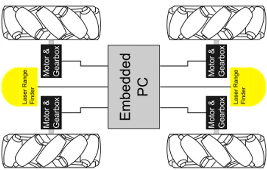
Fig. 2. Embedded PC as a central controlling unit
capabilities and utilizing the sensor data from safety laser range finders and sensor network nodes, already installed for safety and communication reasons, this approach minimizes the costs needed to implement autonomous navigation and rises the flexibility of the system by providing an open pro-gramming environment capable of executing even resource hungry algorithms for further extending the system. For ex-ample detecting obstacles and using the position information of the detected obstacles during path planing is as simple as implementing the new algorithm in C or C++ and load it as standard shared object into the control environment.
This paper focuses on the overall design chosen to form the base of a integrated control and navigation system for omnidirectional Mecanum-wheel based AGVs, including the implemented Inter-Process Communication (IPC) layer linking hard real-time task with userspace client programs.
In contrast to related works like RoboBuntu (described in [14]) this project does not focus on a ready to use distribution but on providing a integrated control system running on any Xenomai enabled Linux installation. Furthermore this project is not limited to middleware functionality like Miro (described in [15]) focusing on localization and general robot behavior services. By including low-level controllers, this project aims to be independent of a underlaying second real-time low-level control system. Instead of focusing on integrating as much functionality as possible to become a general-purpose robot control package like OROCOS (de-scribed in [16]) does, this project focuses on providing a sophisticated and full featured control system for omnidi-rectional mobile robots used for dynamic and autonomous navigation.
II. SYSTEMARCHITECTURE
The architecture described in this paper provides a control environment for omnidirectional AGVs. It features a cen-tralised design utilizing an embedded PC with a powerful CPU providing all required computational processing pow-ers. All sensors and actuators, like the safety laser range finders or the motors used in the AGVs drive, are directly connected to an embedded PC using standard interfaces like RS-422 and Controller Area Network (CAN) or are indirectly connected through CAN controllers (see Fig. 2).
By directly connecting the two 270◦ SICK S300 safety
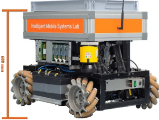
Fig. 3. Mecanum wheeled based omnidirectional AGV
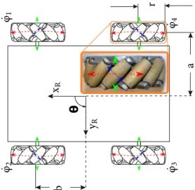
Fig. 4. Coordinate systems and degrees of freedom on the plain
environment believes the AGV to be at during the measure-ment. This information is used by localization algorithms to allow an exact position estimation even through fast movements of the AGV. Together with distance information obtained through the IEEE 802.15.4a sensor network precise position deltas can be calculated. This deltas are then used by the position control algorithm and the path planner to eliminate drifts based on constraints given by the user.
For real life experiments, the discussed software frame-work architecture is deployed on three different types of om-nidirectional AGVs without the need for any adoption of the software. One AGV was build by the IMSL team (see Fig. 3), while the second AGV is a commercial system targeted at educational and scientific facilities. A third type of AGVs are commercial systems used in industrial environments. While only the self build omnidirectional AGV is equipped with an electronic load lift suitable for AGV scenarios, all AGVs feature a Mecanum wheel based omnidirectional drive. With this holonomic drive, all AGVs can make use of all three, the two coordinate degrees and the orientation of the AGV, degrees of freedom on the plane (see Fig. 4). Not only the AGVs can drive sideways, they also can freely change their orientation while driving in one direction on a straight line. Combining the localization engine and the electronic load lift, the self build AGV can autonomously load and unload euro bins through specially crafted stations. In this scenario the AGV uses the omnidirectional drive and the precise positioning information provided by the localization engine to access a station. Using the electronic load lift either a euro bin formally transported by the AGV is then unloaded to the station or a euro bin resting on top of the station is picked up by the AGV.
Regarding the schematic structure displayed in Fig. 2, the self build AGV displayed in Fig. 3 uses non-integrated ampli-fiers external to the motors. Each of the four ampliampli-fiers takes an analog set-point. The second non-displayed AGV uses fully embedded motors containing an integrated amplifier,
Fig. 5. Mecanum wheel with schematics
which take digital set-points through a CAN interface. The design of the third commercial AGV type features a safety PLC containing the required transformation from set-points in AGVs frame into the four wheel speeds then handled by the four motors’ integrated amplifiers. This type of AGVs was tested in real life with two vehicles formerly operated by hand. Both vehicles already contained a safety PLC for transforming the operators commands into wheel speeds. The employed PLC already handles all safety concerns and therefore was required to coordinate the actual set-points handed to the motor amplifiers. For this third type of AGVs set-points in AGV’s frame are used as set-point towards the safety PLC. From the controllers point of view the main difference between the first and the other AGV types is that the fully integrated motors feature a digital closed-loop controller. The integrated controllers are directly (as for the second type) or indirectly (as for the third type through the safety PLC) parameterized through the CAN interface and follow the digital set-point dictating the speed in revolutions per minute (RPM) more precisely. In contrast the separate motor amplifiers, used with the first AGV, are featuring an analog closed-loop controller that only directly controls the motor’s current. Because of this difference, an additional control layer is needed for the self build AGV. This additional layer forms a second closed-loop controller that uses the motor’s encoders to derivate the actual motor speed and sets a suitable set-point.
A. Mecanum Wheels and Mecanum Wheel Based Drives
The Mecanum wheel has a special design that allows omnidirectional movements with just one motor per wheel. Instead of changing single or all wheels orientation relative to the chassis, passive free moving rollers are placed on the wheel’s hub (see Fig. 5). This passive rollers are typically made of rubber or other flexible plastics like Vulkollan, to maximize the friction and weight distribution of the whole wheel.
Through the special form of the rollers and the wheel hub, a Mecanum wheel has nearly a round form like a normal tire (see Fig. 5). For this reason the most basic cases a Mecnaum wheel could be viewed like any other wheel of the same diameter. By design simple forward and backward movements are accomplished by moving all four wheels equaly.
Fig. 6. Mecanum based AGV with the AGV’s coordinate system and Mecanum forces vectors
in red) and an external force that draws the wheel sideways (doted in green) can add to a force standing perpendicular on the rollers axis (dash-doted in blue). The external force (doted in green), which draws the wheel sideways, is a product of the forces created by the other three Mecanum wheels. Being connected by a common chassis, the forces created by the other motors add up to the external force vector (see Fig. 6). The overall resulting movement of the AGV depends on the speed of all four motors.
Fig. 6 shows two ways to defines the AGV’s velocity. The three parameters (xR, yR andθ) shown at the center of the AGV define the internal coordinate system of the AGV. The four other parameters printed next to the wheels (ϕ˙1,ϕ˙2,ϕ˙3 and ϕ˙4) are the wheel speeds of the Mecanum drive. This two parameter sets need to be transformed both ways by the controller for steering the AGV. The internal coordinate system, which stays fix with the AGV and moves alongside the AGV in the world frame, is defined by the two axis
xR and yR, that describes a position relative to the AGV’s center, and θ which describes the orientation with respect to world coordinate system. While the AGV’s pose changes inside the world coordinate system and stationary objects like walls stay fixed, in the AGV’s internal coordinate system everything mounted to the AGV, like the safety laser range finders, stays fixed an everything else changes its poses. This way obstacles like walls or furniture can easily be handled through the sensors. For steering the AGV, velocities given in the AGV coordinate system are used. This way the AGV drives forward if a positivex˙Rspeed is given, while setting a positive y˙R speed lets the AGV drive to its left. Turning the AGV is possible by using a velocity given as angular velocityθ˙.
For actually moving the AGV, the given velocities need to be transformed into wheel speeds. As equation 1 shows (variablesr,aandbare defined in Fig. 6), the three parts of the velocities in the AGV’s coordinate systemx˙R,y˙Randθ˙ are transformed into four wheel speedsϕ˙1,ϕ˙2, ϕ˙3 andϕ˙4. While the two translatoric degrees of freedom can be directly mapped to the four wheel speeds, mapping the rotational speedθ˙also requires knowledge about the distance between the left and right wheel pairs (in Fig. 6 half the distance is marked as a) and the front and rear axis (in Fig. 6 half
ϕ˙3
˙
ϕ4
=
r 1 −1 −(a+b)
1 1 (a+b)
y˙R
˙
θ
(1)
For calculating the odometry pose of the AGV, the inverse equation 2 (variablesr,aandbare defined in Fig. 6) is used. The four dimensional vector of wheel speeds is turned into the three dimensional vector of speeds defined by the AGV internal coordinate system. To calculate the odometry pose this speed vector needs to be integrated over time. Because of the lost information in the odometry pose a controller error, still visible in the wheel speed vector, can not be detected through the odometry data. In consequence not only the odometry pose is required as controller feedback, but also the raw wheel speeds need to be taken into account for calculating the correct set-point. By integrating the possible erroneous speed vector of the backward transformation, also an error is integrated into the odometry pose. For this reason an sophisticated localization engine is needed to remove this errors from time to time. Even through only using the odometry data would be too error prone it is possible to use odometry data between two localization steps.
˙
xR
˙
yR
˙
θ
= r
4
1 1 1 1
−1 1 −1 1
1
a+b −
1
a+b −
1
a+b
1
a+b
˙
ϕ1
˙
ϕ2
˙
ϕ3
˙
ϕ4
(2) While offering a great flexibility, Mecanum based drives require high grade closed-loop controller, which also takes care of the coupling of the speeds of all four wheels. The controller software created by the authors is based on the concepts described in [8].
B. Control Architecture
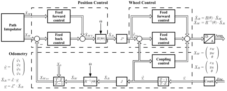
The modular control framework provides different con-trollers, which are parametrized at runtime. In depends to the underlaying hardware of the AGV a set of controllers is chosen for precise control of the given AGV. Fig. 7 shows the full structure of the used control hierarchy, which is based on the classical cascade control and the model based control for Mecanum-wheel based vehicles developed in [8].
The control hierarchy includes a PD position controller and a PID speed controller for each wheel. A feedforward controller part is also implemented in both position and the wheel control. The position control uses the odometry pose tracked by the odometry module starting from an initial poseX0using the data received from the motor’s encoders. For a more accurate odometry a gyroscope can be used to measure the AGVs true orientationθ, which is used for the transformation R−1(
θ) between velocities in world frame coordinates and corresponding velocities in the AGVs R -frame. The Jacobian matrix J and its pseudo-inverse J∗
Fig. 7. Controller structure
the four wheel speeds derived from the motor’s encoders. This very same wheel speeds are also used by the coupling control to fix coupling errors created by the underlaying hardware because of the small differences in following the given set-point of all four motors and gears.
The first custom-built AGV uses all components displayed in Fig. 7, while the other two AGVs discussed in this paper do not use the wheel control part and the position control directly generates the output set-point for the underlaying hardware. The position control is executed every 15 ms as a real-time task, receiving its set-point from the path interpolator. With the first custom build AGV the position control sets the set-point of the wheel control, which is executed every 3 ms also as a real-time task.
The analog drive units of the custom-built AGV consist of brushless 3-phase DC servomotors with gearing and resolvers. By design the Mecanum drive consists of four drive units. Resolver feedback provides input to the ana-log quadrature axis servo controller, while the set-point is provided through analog DC signals by the embedded PC. The servo controller accomplishes commutation, control of phase currents, pulse-width modulation, power amplification and generation of incremental pulses. Because of the com-pensation of electrical time constants by means of analog current control a nearly immediate request of a desired motor torques can be assumed.
C. Software Structure
The software system developed by the authors aims to be compatible with different AGV hardware by implementing a generic control structure for omnidirectional AGVs. This is necessary because of the different characteristics of the target AGVs used. The first AGV, using four analog motor amplifiers, require an additional closed-loop controller in software, to ensure a comparable wheel speed on all four motors when the same set-point is given. For the other AGV types this is not necessary.
To respect this differences, the overall design is struc-tured into separate modules, with communication channels transferring data between the modules. As Fig. 8 shows, the developed software contains two closed-loop controllers.
The lower end controller, titled “Wheel Control” in Fig. 8, operates on the wheel speeds of the four motors. The set-point of the controller is the desired value of the analog motor amplifiers used in the first AGV. Because of the higher quality of the controllers integrated in the motors of the other AGV types, this lower controller is not needed for the second and third type of AGVs. The second higher level controller ti-tled “Position Control” in Fig. 8 controls the AGV’s position in a fixed world coordinate system. This controller is required to compensate positioning errors not visible to the wheel control. The controller is also using information about the remaining errors lost in the backward transformation from wheel speeds to velocities in the AGV’s coordinate frame, to fix errors in the coupling of the four wheels (referenced as “Coupling Control” in Fig. 7). The “Position Control” is also responsible for that the AGV arrives at the set-point that is given by either the “Path Interpolator” or the “Joystick Steering“ module. The feedback for this set-point tracking is done by the “Odometry” module, which transforms the four wheel speeds into a position information. As shown in Fig. 8 the set-point handed to the AGV’s hardware is either provided by the wheel control or directly by the position controller. For the first AGV requiring a wheel speed control layer in the software, a vector of four wheel speeds is handed over to the hardware layer. For the two other types of AGVs the position control provides the set-point either as a vector of four wheel speeds, like for the second AGV, or in speeds of the AGV’s frame, like for the third type of AGVs. This different set-point handling is part of the modular design, that ensures, that the developed software can be used with a wide range of different AGV types.
Fig. 8. Simplified system structure
a jitter on the set-points send towards the motors and as a result the AGV would move in stop and go manner.
To gain a high grade controller behavior, a real-time Linux system is used. By employing a real-time operating system the performance of all low level controllers as well as all time critical high level functionality is guarantied. In contrast to other real-time operating systems, real-time Linux systems allows the parallel execution of real-time and non-real-time tasks on the same system. This allows all components shown in Fig. 8 to be executed on the same embedded PC.
1) Real-Time Linux: Real-time Linux systems available today represent an ongoing effort started in the mid 90s. With both highly flexible Linux systems on the one hand and real-time systems suitable for precise real-time execution on the other hand, developers started to join the benefits of both types of operating systems. Today most real-time Linux systems are following a micro kernel based approach to implement a fast interrupt processing. They have reached a comparable quality compared to other real-time operating systems as show in [17]. Even the standard Linux kernel, without an additional micro kernel, is aiming to implement hard real-time capabilities. This approach called Linux-RT is described in [18] and could, once merged into the main Linux version, provide a good out of the box real-time behavior for most Linux systems.
The authors have compared different real-time Linux ex-tension in [19] (in German) and settled for the micro kernel based extensions RTAI (at first) and Xenomai (currently used). While both extensions offer sufficiently good real-time scheduling, Xenomai has a much broader device support, like drivers for popular CAN controllers, through real-time device drivers developed by the Xenomai project.
For the controller program described, the closed-loop controllers are executed periodically. The first AGV uses the wheel speed controller setup as a periodic task with a period of 3 ms. The position controller triggered through semaphores every 5th execution of the wheel speed controller and has therefore a period of 15 ms. In case of the second AGV, the wheel speed controller is not executed at all and the position controller is setup directly as an periodic task of 15 ms periodicity.
III. CONCLUSIONS
In this paper, a modular control architecture which is built on top of a real-time Linux system is presented. The control architecture was implemented and tested in three different AGVs with different controller concepts. Due to the modular design the control system can easily adapted to new kinds of AGVs and controller designs, which removes constraints
REFERENCES
[1] MobileRobots Advanced Robotics Interface for Appli-cations (ARIA) - ARIA Developer’s Reference Manual, http://robots.mobilerobots.com/wiki/ARIA, 2012.
[2] Segway Robotic Mobility Platform (RMP) - Interface Guide, Segway LLC, 14 Technology Drive, Bedford, NH 03110, 2005.
[3] M. Blackwell, “The uranus mobile robot,” Carnegie Mellon University, Tech. Rep., 1990.
[4] A. Hormann and U. Rembold, “Development of an advanced robot for autonomous assembly,” inProc. of the 1991 IEEE International Conference on Robotics and Automation (ICRA), vol. 3, apr 1991, pp. 2452–2457.
[5] R. Dillmann, J. Kreuziger, and F. Wallner, “Priamos: An experimental platform for reflexive navigation,”Robotics and autonomous systems, vol. 11, no. 3-4, pp. 195–203, 1993.
[6] P. Muir and C. Neuman, “Kinematic modeling for feedback control of an omnidirectional wheeled mobile robot,” inRobotics and Automa-tion. Proceedings. 1987 IEEE International Conference on, vol. 4. IEEE, 1987, pp. 1772–1778.
[7] R. Dillmann, J. Kreuziger, and F. Wallner, “The control architecture of the mobile system priamos,” inProc. of the 1st IFAC International Workshop on Intelligent Autonomous Vehicles. Southampton, 1993. [8] A. Jochheim, “Controller design for multivariable systems under
the restriction of the given coupling constraints (Reglerentwurf f¨ur Mehrgr¨oßensysteme unter der Nebenbedingung vorgegebener Aus-gansgr¨oßenverkopplungen),” Ph.D. dissertation, FernUniversit¨at Ha-gen, 1995.
[9] K. Furmans, C. Nobbe, and M. Schwab, “Future of material handling– modular, flexible and efficient,” in Proc. of the Workshop Metrics and Methodologies for Autonomous Robot Teams in Logistics at IROS 2011, 2011.
[10] L. Schulze, S. Behling, and S. Buhrs, “Development of a micro drive-under tractor-research and application,” in Proceedings of the International MultiConference of Engineers and Computer Scientists, vol. 2, 2011.
[11] C. R¨ohrig, D. Heß, C. Kirsch, and F. K¨unemund, “Localization of an omnidirectional transport robot using ieee 802.15.4a ranging and laser range finder,” in Proceedings of the 2010 IEEE/RSJ International Conference on Intelligent Robots and Systems (IROS 2010), October 2010, pp. 3798–3803. [Online]. Available: http://www.inf.fh-dortmund.de/personen/professoren/roehrig/papers/iros10.pdf [12] C. Kirsch, F. K¨unemund, D. Heß, and C. R¨ohrig, “Comparison
of localization algorithms for agvs in industrial environments,” in
Proceedings of the 7th German Conference on Robotics (ROBOTIK 2012), Munich, Germany, May 2012, pp. 183–188.
[13] F. K¨unemund, C. Kirsch, D. Heß, and C. R¨ohrig, “Fast and accurate trajectory generation for non-circular omnidirectional robots in indus-trial applications,” inProceedings of the 7th German Conference on Robotics (ROBOTIK 2012), Munich, Germany, May 2012, pp. 377– 382.
[14] A. Mancini, E. Frontoni, A. Ascani, and P. Zingaretti, “Robobuntu: A linux distribution for mobile robotics,” inRobotics and Automation, 2009. ICRA ’09. IEEE International Conference on, may 2009, pp. 2544 –2549.
[15] H. Utz, S. Sablatnog, S. Enderle, and G. Kraetzschmar, “Miro -middleware for mobile robot applications,”Robotics and Automation, IEEE Transactions on, vol. 18, no. 4, pp. 493 – 497, aug 2002. [16] H. Bruyninckx, “Open robot control software: the orocos project,”
in Robotics and Automation, 2001. Proceedings 2001 ICRA. IEEE International Conference on, vol. 3, 2001, pp. 2523 – 2528 vol.3. [17] A. Barbalace, A. Luchetta, G. Manduchi, M. Moro, A. Soppelsa, and
C. Taliercio, “Performance comparison of vxworks, linux, rtai and xenomai in a hard real-time application,” inReal-Time Conference, 2007 15th IEEE-NPSS, 29 2007-may 4 2007, pp. 1 –5.
[18] W. Betz, M. Cereia, and I. Bertolotti, “Experimental evaluation of the linux rt patch for real-time applications,” inEmerging Technologies Factory Automation, 2009. ETFA 2009. IEEE Conference on, sept. 2009, pp. 1 –4.