Abstract- This paper presents an inversion methodology through
weighted least squares to obtain the electrical parameters for the soil of a typical mid-western region in Brazil using the model based in the formalism of the parabolic equations to calculate the electric field intensity received. To validate this methodology, the results of the radio signal measurement campaign conducted in six radial routes leaving the city of Brasilia, Federal District, where the transmitter was located, were used. The measurements were compared to computer simulations and, thus, the optimal values for the electric conductivity and relative permittivity for the soil of the region could be estimated. Finally, a quantitative analysis of these parameters was performed with the values found in the literature, which demonstrated the effectiveness of the proposed methodology.
Index Terms—conductiv; electric field; inversion; parabolic equations; permittivity.
I. INTRODUCTION
Since 2005, the Brazilian government, through the National Telecommunications Agency,
ANATEL, has been authorizing digital signal transmission tests aimed at the implementation of the
future Brazilian model for digital radio broadcast for frequencies below 30 MHz, in compliance with
the recommendations of the Nr. 22 NTC Technical Standard. The standards of Digital Radio
Mondiale (DRM) and High Definition (HD) were chosen for the tests because of the compatibility
between their frequency bands and the current bands designed to radio broadcast in Brazil, thus
allowing for the coexistence of both analog and digital systems.
Regardless of the standard that will be adopted, studying the behavior of the signal generated by the
stations that will use the new systems for digital radio broadcasting in Brazil is required as well as the
knowledge of the electrical parameters of the soil, especially in the Medium Wave band, where the
effects of terrain strongly influence the determination of the electric field received and, therefore, the
determination of the coverage area of these stations.
Inversion Method for Obtaining Electrical
Parameters for Soil in the Rural Region in Brazil
Rômulo A. N. Oliveira1,2, Fátima N. B. Magno1,João F. Souza1, Klaus Cozzolino1, Gervásio P. S. Cavalcante1
1.Federal University of Pará, Av. Augusto Correa, 01, CEP 66075-110, Belém, PA, Brazil- UFPA
2. Federal Institute of Science and Technology of Pará, Av. Alte. Barroso ,1155, CEP 66093-020, Belém, PA, Brazil -IFPA
Thus, it is paramount to use appropriate values for the electrical parameters of the soil in the
calculation of the electric field intensity during the planning of these systems, mainly because digital
systems are much more sensitive, where small changes in the value of the electric field may cause
total signal loss in the receiver.
This paper presents a method of inversion through weighted least squares to obtain the electrical
parameters of the soil in a typical region in mid-western Brazil, which is characterized by highways or
streets that cut through rural areas, where for this region, the World Atlas of Ground Conductivities of
recommendation ITU-R P.832-2 [1] recommends a value of 1 mS / m for the soil electrical
conductivity.
The formulation of the inverse problem using the weighted least squares was considered because it
is the form that more quickly leads to the convergence of results in the majority of the optimization
techniques currently in use [2-3].
To analyze the methodology proposed herein, the results obtained in the campaign for electric field
intensity measurement conducted over six radial routes leaving the city of Brasilia, Federal District,
toward a rural region in mid-western Brazil [4] were used; also, the electric field was calculated
through the method based on the formalism of the parabolic equations [5], whereas this method was
used because it shows values very close to those obtained in measurements when compared to some
of the classic models used in determining loss of propagation.
The measurement system consisted in a stationary laboratory transmitting a carrier at 980 kHz and
two mobile units that were mounted to measure and store the instantaneous values of received signal
strength. The results of measurements were compared with computational simulations through the
method of inversion proposed.
II. METHODOLOGY
In the study of the behavior of a system through a mathematical model, it is essential to have
knowledge of the various parameters involved, such as the information at the system input and
boundary conditions. However, if some of these parameters are unknown, it is necessary to first
consider the inverse problem, where the information about the response of the system will be
available a priori. After this step, solving the direct problem is commenced.
By conducting measurement campaigns, the unknown parameters of the system can be found using
the solution of the inverse problem, where determining a vector of unknown parameters that will
minimize the difference between the measured values and the values obtained from the simulated
response by a model that describes the system is attempted. This difference is known as the cost
function, where minimization thereof will represent the optimization of said parameters.
Amongst the techniques used in the literature for the minimization of the cost function, this paper
A. Cost Function
For this paper, the cost function based on weighted least squares that have the following
representation [3] was selected:
x 1
2 W ∙ ̅ x W ∙ x x (1)
where x represents the vector of unknown parameters of the model, μ is a regularization factor, also
known as Lagrange multiplier and ̅ x represents the vector of residuals. The term W is the inverse
of the data covariance matrix describing the variance represented by the weight of each measurement
mj and estimated correlation existing between the errors. The parameter χ provides an a priori
estimate of the noise present in the data. The term W is the inverse of the covariance matrix of the
model, given as a priori information and represents the importance of each element in the vector x.
The residual vector ̅ x is defined as a vector containing M elements representing the j-th error
between the j-th measurement mj and the corresponding j-th response simulated by the model Sj. The
normalized representation thereof is given by:
e x
x ⋮
x
! x " ⋮ ! x "
S x m#, (2)
B. Newton’s Method
The Newton's method is a quadratic model of the cost function and its representation through the
first three terms of the Taylor series expansion around the k-th iteration x% is given by [3]:
x% p% & x% g' x% ∙p% 1
2p%'∙G x% ∙p% (3)
where the step in x% toward the minimum of the cost function x is:
p% x%( x% (4)
and g x ) x is the gradient vector of the cost function defined as:
g x ) x *+,≡ .
./,, 0 1,2,3, ⋯ , 34
J
5' x ∙W'∙W ∙e x W'∙W ∙ x-x (5)
Where J̿ x is the Jacobian matrix of order MXN given by:
J̿ x *J8, ≡. 8
./, , " 1,2,3, ⋯ , 9; 0 1,2,3 ⋯ , 34 (6)
and G x )) x is the Hessian of the cost function x represented by:
G x )) x <=,8≡ .
./,./8 , 0, " 1,2,3 ⋯ 3>
W'∙ W @J̿' x ∙W'∙W ∙J̿ x Q x A (7)
In the term Q x , the second order information of the cost function x is represented.
The minimum of the cost function is achieved when the step p% is the minimum of the function
∅ p% g' x% ∙p% 1
2 ∙p%'. =̿ x% ∙p%
(8) Making the gradient ∅ to be null in p0:
)∅ p0 =̿ ∙p0 g 0 (9)
By solving (9), a stationary point of the cost function is found, i.e., a point of minimum, maximum
or saddle point in p% p0. Thus, this stationary point is the solution to the following set of linear
equations:
=̿ ∙p0 g (10)
In the implementation of the Newton’s method conducted herein, =̿ x% was considered a
nonsingular matrix and positive definite, which results in a unique solution to (10) given by:
p0 =̿ ∙g (11)
In this case, there is only one stationary point p0 in a descent direction, i.e., toward the minimum of
the cost function, since:
x% p0 x% < 0 (12)
Substituting p0 in (3), the following is obtained:
C(xk p0) ≈C (xk
1 2g
T
(xk .G
F
(xk .g(xk (13)
The equation (13) represents the cost function at its minimum value, where x% is the optimal vector
of unknown parameters of the model and p0 is known as Newton's search direction.
III. PARABOLIC EQUATION MODEL
To calculate the simulated response, the model based on the formalism of parabolic equations [5]
was used herein. This model was chosen because it obtained values of electric field intensity much
closer to the values obtained in the measurement campaign in the region [6]. Moreover, this model
uses lower computational effort [7-8].
Initially, an environment made up of small streets with buildings and vegetation was considered.
Then, the method of parabolic equations was applied for calculating the electric field considering the
electrical parameters involved in this simulated environment.
To the solution of the parabolic equation, the finite difference scheme of Crank-Nicolson was used
for small angles (up to 20 degrees).
The parabolic equation for small angles is given by: [5]
( )
( )
(
( )
)
( )
2
2 2
2 , 2 , , 1 , 0
u u
x z ik x z k n x z u x z
x z
∂ + ∂ + − =
∂
∂ (14)
1 2
0
2 r
i n
f σ ε
π ε
= +
(15)
where εr is the relative permittivity, σ is the conductivity (S / m), f is the frequency (Hz), ε0 is the
permittivity of free space (F / m).
Making the discretization of 14 in direction x and z through the finite difference scheme of
Crank-Nicolson, where ξm =
(
xm−1+xm)
2 is the midpoint in the solution xm-1 to xm, m(
,)
j m j
u =u x z ,
(
2)
4
b= ik ∆z ∆x and amj =k2
(
n2(
ξm,zj)
− ∆1)
z2, the following is obtained [10]:(
)
1(
)
1 11 1 1 1
2
2
m m m m m m m m
j j j j j j j j
u
− + +
b
a
+
u
++
u
−=
u
−+ −
b
a
−
u
+−−
u
−− (16)To calculate the propagation loss through the parabolic equations method, the equation below was
used: [11]
10 10 0 10
(
)
36,57 20log
20log
20log
T RL dB
=
+
f
+
u
−
u
−
G
−
G
(17)Where u0 is the electric field at a reference distance (d0), u is the received electric field, f is the
frequency in GHz, and GT and GR are the gains of the transmitting antennas and receiving in dB,
respectively.
IV. DESCRIPTION OF ENVIRONMENT AND MEASUREMENT SYSTEM
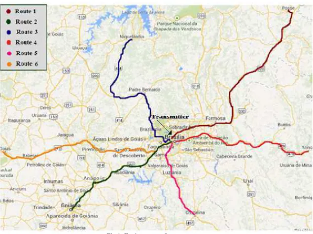
In order to validate the methodology of inversion presented in this paper, the results of the
measurement campaigns of electric field intensity carried out by the National Telecommunications
Agency - ANATEL - and by Brazilian Communications Company - Radiobrás in six radial routes
from the city of Brasilia, Federal District, towards the cities of Passo (Route 1), Goiânia (Route 2),
Niquelândia (Route 3), Arinos (Route 4 ), Crystal (route 5) and Goiás (route 6), where the
environment of these routes is characterized by a typical rural region of centre of Brazil, were used.
Fig.1: Environment of measurements
The transmission system consisted in a Medium Wave generator, which was mounted at the
Radiobras headquarters in Brasilia, located in Block 1, Lot S / N, in the Plano Piloto. Table I shows
the characteristics of the transmitter.
TABLE I – CHARACTERISTICS OF TRANSMITTER.
Location Downtown Brasilia
15°49’31,44” S 47°57’49,89” W Center frequency 980 kHz
Bandwidth 10 kHz Transmitter Power 50 kW ERP Electric field nominal (Enom) 1.250 µV/m
Antenna height 94 m
For the measurements performed on routes 1, 2 and 6, the mobile unit of ANATEL was used,
assembled in France by Thales Communications. This unit has equipment for the measurement of
technical parameters, such as modulation type, frequency, electric field intensity, spectrum analysis
Fig.2:The equipment setup in the mobile unit of ANATEL [11]
Initially, an AM signal was captured by the monopole antenna RN4203 that sent it to the switch of
antenna AEA196. Then, the signal was sent off to the REC108 receptor, which has two modules, the
first of which translates the signal of radio frequency (RF) to intermediate frequency (IF), and the
second one samples and demodulates the signal. After this step, the signal samples were sent to the
central processing unit KPRII, which obtained the values of the electric field intensity for each sample
of the signal at intermediate frequency.
For the collection and storage of the geographic coordinates for the samples of the received signal
in IF, a Trimble GPS connected to the RS232 of KPRII was used.
Also, a handheld GPS connected to a Palm Top was used for registering the geographic coordinates
of the places where there occurred abrupt changes in the intensity value of the measured electric field.
For the measurement campaign on routes 3, 4 and 5, a mobile unit of Radiobras was used, with the
participation of members of the consortium DRM (Digital Radio Mondiale). Fig.3 shows the
Fig.3:The equipment setup in the mobile unit of Radiobras [12]
This mobile unit had a short monopole antenna, model HE010, which received an AM signal and
delivered it to a PSU (Power Supply Unit). Then, the signal was send to the EB200 receiver for
translating the RF band to the IF band and baseband. After this step, the signal followed to a 24-bit
Creative Sound Blaster sound card, which was connected to a USB port on a Lap Top. This Lap Top
contained the Dream DRM and TSR software that demodulated the signal and captured of the value
of the electric field intensity.
For each sample obtained by TSR DRM software, the value of the electric field intensity received
was stored. Also, information of the geographic coordinates of each sample measured using a GPS
was stored.
V. RESULTS
This section presents the results obtained from the use of the inversion methodology through
weighted least squares in the estimation of the electrical parameters of the soil in a region in
mid-western Brazil.
This region consists of a rural environment where radio signal measurements were conducted in six
radial routes leaving the city of Brasilia, Federal District, where a transmitter was installed in a
building of the Brazilian Communications Company located in the center of Brasilia, which emitted
an amplitude-modulated signal by a collinear antenna positioned 94m high.
For the measurement campaign, two mobile units were used: one of ANATEL (routes 1, 2 and 6)
and another of Radiobras (routes 3, 4 and 5).
The Visual FORTRAN 6.0 program was used both to obtain the values of electric field intensity
soil. A vector x of unknown parameters of the model was set, which consisted of two elements: soil
electrical conductivity and relative permittivity of the soil.
The value of the Lagrange multiplier
used was 1 x 10
-8.
TABLE II. ELECTRICAL PARAMETERS ESTIMATED TO SOIL
Route Electrical Conductivity mS/m
Relative Permittivity
01 3.9 17
02 4.0 17
03 4.0 17
04 3.7 17
05 3.3 16
06 4.2 16
After application of the inversion method proposed herein, the values for soil electrical conductivity
and relative soil permittivity were calculated and considered to be homogeneous over the six routes
shown in Table II.
In Table II, the estimated values for the electrical conductivity of soil in the six routes are can be
seen to be much higher than the value recommended by the ITU for the region in mid-western Brazil.
However, they are very close to the results found by LIMA [12] who developed a methodology that
estimated the soil electrical conductivity by comparing the measured values of the attenuation of the
signal with the values found through the Earth Spherical model for surface wave.
For the relative permittivity of the soil, the values estimated by using the inversion methodology in
the six routes considered were verified to be slightly higher than the value adopted in [12], indicating
the existence of a medium-type soil.
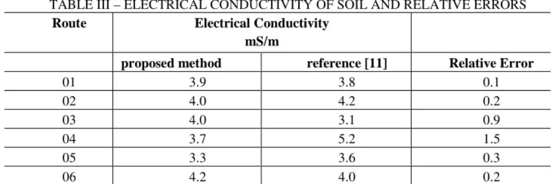
TABLE III – ELECTRICAL CONDUCTIVITY OF SOIL AND RELATIVE ERRORS
Route Electrical Conductivity mS/m
proposed method reference [11] Relative Error
01 3.9 3.8 0.1
02 4.0 4.2 0.2
03 4.0 3.1 0.9
04 3.7 5.2 1.5
05 3.3 3.6 0.3
06 4.2 4.0 0.2
In order to evaluate the performance of the proposed model, Table III shows the optimal values of
soil conductivity estimated by using the inversion methodology and those obtained in reference [12];
also, the relative errors between the two methods for each one of the six routes are presented.
In Table III, it can be observed that the values of the soil electrical conductivity for routes 1, 2, 5
and 6 are very close to the values obtained in reference [12] producing small relative errors, which are
slightly larger for routes 3 and 4.
These values for the conductivity of the soil are also very close to those found in reference [13],
where the same routes studied here through a methodology based on Artificial Neural Networks were
VI. CONCLUSION
This paper presented a methodology of inversion through weighted least squares to obtain the
electrical parameters of the soil in a region in mid-western Brazil. Also, a comparative analysis
between the values of the soil electrical conductivity through this methodology and the values found
in the literature for the region was carried out.
To validate this methodology, the results of the measurement campaigns of the intensity of the
electric field in six radial routes leaving the city of Brasilia bound for the neighboring cities were
used, in an environment characterized by a typical rural region of mid-western Brazil. The electric
field through the formalism based on the parabolic equation model was also calculated, since this
model showed good concordance with the values obtained from the measurement campaigns.
The electrical parameters of the soil were estimated for the six routes studied using the inversion
methodology presented, whereby the values obtained for the electrical conductivity of the soil were
found to be higher than those recommended by the ITU, thus indicating that the coverage areas of
local radio stations would be much higher than those established by ANATEL.
These estimated values for the electrical conductivity in the six routes were also found to be very
close to the values found in recent studies conducted in the rural region in mid-western Brazil [12-13],
showing small relative errors in the routes 1, 2, 5 and 6. Similarly, the values for the relative
permittivity of the soil in the six routes were close to those adopted in the region.
Thus, it can be concluded that, by using the inversion method presented herein, it will be possible to
find suitable values for soil electrical conductivity and relative permittivity of the soil, thus making it
much easier to determine the electric field received with greater precision.
For future papers, obtaining the electric parameters of the soil, considering it inhomogeneous in
each route, is suggested, and studying the changes in the values of electrical parameters with distance
is also proposed.
ACKNOWLEDGMENT
The authors would like to thank the National Institute of Science and Technology – Wireless
Communication (INCT-CSF) for its support.
REFERENCES [1] Rec. ITU-R P.832-2: ‘World atlas of ground conductivities’, 1999.
[2] Habashy, T. M: ‘A General Framework for Constraint Minimization for the Inversion of Electromagnetic
Measurements’ appeared as a chapter in the book series Progress in Electromagnetic Research, PIER 46, pp. 265-312, 2004.
[3] Habashy, T. M: ‘An inversion methodology using a weighted least- squares constrained minimization approach’. Research note, Schlumberger-Doll Research, 2003.
[4] Lima, F.F., Soares, A.J.M., Junior. A. and Silva, L.M. da: ‘Field Intensity Measure in Medium Waves for Broadcasting Digitalization Planning in Brazil’. IEEE AP-S/URSI/AMEREM 2006 Symposium.
[5] Levy, M.: ‘Parabolic Equation Methods for Electromagnetic Wave Propagation’, London: Institution of Electrical Engineers (United Kingdom, 2000, 1st edn.), pp. 1-236.
[7] Souza, J. F. de, F. N.B., Valente. Z. A., Costa, J. C. and Cavalcante, G. P. S. ‘ Mobile Radio Propagation along Mixed Paths in Forest Environment using Parabolic Equation’, Microwave and Optical Technology Letters, Vol. 51 (4), April 2009, pp. 1133-1136.
[8] Oliveira, R. A. N. de, Souza, J. F. de, Magno, F. N. B., Cozzolino, K. and Cavalcante, G. P. S. ‘Propagation Loss Path Prediction Using Parabolic Equations for narrow and wide angles’, 7th European Conference on Antennas and
Propagation (EUCAP) 2013, pp.944-948.
[9] Wangsness, R. K.: ‘Electromagnetic Fields’, United States of America: John Wiley & Sons, 1979, pp. 34 – appendices. [10]Premat, E.: ‘Prise en Compte d´effets Météorologiques dans une Méthode d´Eléments finis de Frontière’, thèse de
docteur, France, pp. 259-261, 2000.
[11]Li, L. W., Yeo, T. S., Kooi, Leong, M. S. P. and Koh J. H.: ‘Analysis of Electromagnetic Wave Propagation in Forest Environment along Multiple Paths’, Progress in Electromagnetism Research, PIER 23, 1999, pp. 137-164.
[12]Lima, F. F., Soares, A.J.M., Abdalla, H.A. and Silva, L. M.: ‘Methodology for the Determination of the Ground’s Electric Conductivity in rural Environments trough Measurements of the Surface Wave’, The First European Conference on Antennas and Propagation, Nice, France, 2006.