UNIVERSIDADE DE LISBOA
INSTITUTO SUPERIOR TÉCNICO
Ultrasound Based Navigation and Control for
Orthopaedic Robot Surgery
Pedro Miguel Baptista Torres
Supervisor: Doctor Jorge Manuel Mateus Martins
Co-Supervisor: Doctor Paulo Jorge Sequeira Gonçalves
Thesis approved in public session to obtain the PhD Degree in Mechanical Engineering Jury final classification: Pass with Merit
Jury
Chairperson:
Chairman of the IST Scientific Board
Members of the Committee:
Doctor Carlos Peréz Vidal
Doctor José Manuel Gutierrez Sá da Costa
Doctor João Rogério Caldas Pinto
Doctor Paulo Jorge Sequeira Gonçalves
Doctor João Miguel Raposo Sanches
Doctor Jorge Manuel Mateus Martins
UNIVERSIDADE DE LISBOA
INSTITUTO SUPERIOR TÉCNICO
Ultrasound Based Navigation and Control for
Orthopaedic Robot Surgery
Pedro Miguel Baptista Torres
Supervisor: Doctor Jorge Manuel Mateus Martins
Co-Supervisor: Doctor Paulo Jorge Sequeira Gonçalves
Thesis approved in public session to obtain the PhD Degree in Mechanical Engineering
Jury final classification: Pass with Merit
Jury
Chairperson: Chairman of the IST Scientific Board
Members of the Committee:
Doctor Carlos Peréz Vidal, Professor Titular da Universidad Miguel Hernández
de Elche, Espanha;
Doctor José Manuel Gutierrez Sá da Costa, Professor Catedrático do Instituto
Superior Técnico, da Universidade de Lisboa;
Doctor João Rogério Caldas Pinto, Professor Associado (com Agregação) do
Instituto Superior Técnico, da Universidade de Lisboa;
Doctor Paulo Jorge Sequeira Gonçalves, Professor Coordenador da Escola
Superior de Tecnologia do Instituto Politécnico de Castelo Branco;
Doctor João Miguel Raposo Sanches, Professor Auxiliar (com Agregação) do
Instituto Superior Técnico, da Universidade de Lisboa;
Doctor Jorge Manuel Mateus Martins, Professor Auxiliar do Instituto Superior
Técnico, da Universidade de Lisboa.
Abstract
S
urgical Robotics is an expanding area, contributing to the increased precision and accuracy of surgical procedures, besides producing more reliable and reproducible results, minimizing the invasiveness, reducing complications and improving patient safety, compared with conven-tional techniques. Navigation within the operating room is fundamental to the success of robotic systems. In this context a new navigation system, used in the control loop, to co-manipulate a robotic system developed to assist orthopaedic surgeons, is proposed. Although it may have other applications, the system is designed to perform a hole in the femur head, necessary to im-plant the initial guide wire used in Hip Resurfacing surgery. During the surgery, the bone position and orientation is obtained through a registration process between a set of US images acquired in real time and the CT femur model, preloaded pre-operatively. Contrary to current surgical systems, it does not use any type of implant in the bone, to localize the femur, but passive mark-ers, of an optical measurement system, placed on the probe and the robot to measure their 3D poses. Experimental validation tests were performed on a human’s femur phantom, validating the proposed system.Keywords: Hip Arthroplasty , Surgical Robotics , Image-guided surgery , Ultrasound imaging , Medical image processing , Image Segmentation , 3D Surface Reconstruction , Surface-based Registration , Visual Servoing , Image-based tracking
Resumo
A
exatid ˜ao dos procedimentos cir ´urgicos, al ´em de produzir resultados mais confi ´aveis e re-Rob ´otica cir ´urgica ´e uma ´area em expans ˜ao, contribuindo para o aumento da precis ˜ao e produt´ıveis, minimizando a invasividade, reduzindo as complicac¸ ˜oes e melhorando a seguranc¸a dos pacientes, comparativamente com as t ´ecnicas convencionais. A navegac¸ ˜ao dentro da sala de operac¸ ˜oes ´e primordial para o sucesso dos sistemas rob ´oticos. Neste contexto ´e proposto um novo sistema de navegac¸ ˜ao, usado na malha de controlo, de um sistema rob ´otico co-manipulado, dedesenvolvido para auxiliar os cirurgi ˜oes ortop ´edicos. Embora possa ter outras aplicac¸ ˜oes, o sistema foi desenvolvido para realizar um furo na cabec¸a do f ´emur, necess ´ario ao implante do fio guia na cirurgia de substituic¸ ˜ao parcial da anca. Durante a cirurgia, a posic¸ ˜ao e orientac¸ ˜ao do osso ´e obtida atrav ´es de um processo de registo entre as imagens de US adquiridas em tempo real e o modelo CT do f ´emur, previamente carregado no pr ´e-operat ´orio. Contrariamente aos sistemas cir ´urgicos atuais, n ˜ao usa nenhum tipo de implante no osso para localizar o f ´emur, mas sim marcadores passivos colocados na sonda e no rob ˆo, e um sistema de medic¸ ˜ao ´optico para medir as suas posic¸ ˜oes 3D. Os testes experimentais de validac¸ ˜ao foram realizados numphantom de um f ´emur humano.
Palavras-chave: Artroplastia da anca, Rob ˆos de cirurgia, Cirurgia guiada por imagem,
Ultra-sonografia, Processamento de imagens m ´edicas, Segmentac¸ ˜ao de imagem, Reconstruc¸ ˜ao de Superficie 3D, Registo baseado em superficie, Controlo visual, Seguimento baseado em imagem
Acknowledgements
I
fessor Paulo Jorge Sequeira Gonc¸alves, for the opportunity they gave me to do this work.would like to thank my advisor, Professor Jorge Manuel Mateus Martins and co-advisor Pro-Particularly special thanks to Professor Paulo Gonc¸alves, by having followed closely my work. I would also like to thank Professor Jo ˜ao Miguel Sanches, for its availability and suggestions for the development of this work on image processing component.Thanks to the Portuguese Science and Technology Foundation (FCT) for the PROTEC funding program and also thanks to the advanced training program of the Polytechnic Institute of Castelo Branco.
Finally I would like to extend my thanks all those which in one way or another (providing ideas and / or constructive criticism) were helping anonymously in numerous discussions throughout this work.
This work was partly supported by the Strategic Project,P Est − OE/EM E/LA0022/, through FCT (under IDMEC-IST, Research Group: IDMEC/LAETA/CSI), FCT project P T DC/EM E − CRO/099333/2008 and EU − F P 7 − ICT − 231143, project ECHORD.
Contents
Abstract i
Resumo iii
Acknowledgements v
1 Introduction 1
1.1 Background and Motivation . . . 1
1.2 State of the Art . . . 3
1.3 HipRob project . . . 7
1.4 Objectives . . . 8
1.5 Contributions . . . 9
1.6 Publications . . . 10
1.6.1 Book Chapters . . . 10
1.6.2 Papers in Refereed International Journals . . . 10
1.6.3 Papers in Proceedings of International Conferences . . . 11
1.6.4 Papers in Proceedings of National Conferences . . . 11
1.7 Outline of the Thesis . . . 12
2 Image Acquisition 15 2.1 Ultrasound Image Acquisition . . . 15
2.1.1 Freehand Ultrasound Acquisition System . . . 15
2.1.2 Non Freehand Ultrasound Acquisition System . . . 19
3 Image Processing 23
3.1 Ultrasound Image Processing and Segmentation . . . 23
3.1.1 Segmentation Method . . . 24
3.1.2 Image Processing and Segmentation Results . . . 26
3.1.3 Point Cloud Extraction . . . 33
3.2 Processing and Segmentation of CT Images . . . 34
3.2.1 Point Cloud Extraction . . . 36
3.3 3D Reconstruction and Visualization . . . 37
3.3.1 3D Reconstruction and Visualization Experimental Results . . . 39
4 Image Registration 43 4.1 Introduction . . . 43
4.2 Iterative Closest Point (ICP) Method . . . 44
4.3 Coherent Point Drift (CPD) Method . . . 46
4.4 Experimental Results . . . 46
5 Visual Control of Robotic Manipulator using Fuzzy Models 51 5.1 Introduction . . . 52
5.2 Fuzzy Modeling . . . 54
5.2.1 Off-Line Fuzzy Modeling . . . 54
5.2.2 Takagi–Sugeno fuzzy model . . . 55
5.2.3 Fuzzy Model Parameters Identification by fuzzy clustering . . . 56
5.2.4 On-Line Fuzzy Modeling . . . 57
5.2.5 Uncalibrated Fuzzy Visual Servoing . . . 59
5.3 Experimental Setup . . . 59
5.3.1 Fuzzy Modeling Results . . . 60
5.3.2 Control Results . . . 65
6 Ultrasound Based Robot Navigation 69
6.1 Bone Tracking based on 2D Ultrasound (US) Images . . . 69
6.2 Navigation System Calibration . . . 72
6.3 Robot Navigation . . . 74
6.4 Experimental Setup . . . 79
6.5 Experimental Results . . . 80
7 Conclusions 89 7.1 General Conclusions . . . 89
7.2 Suggestions for Future Work . . . 92
Bibliography 93
List of Tables
3.1 Quantification of segmentation errors . . . 33
4.1 Registration Errors Results, with a cow femur bone. . . 46
4.2 Registration Errors Results of the human femur. . . 48
5.1 Results of the off-line fuzzy model, obtained for each joint. . . 64
5.2 Results of the on-line fuzzy model, obtained for each joint. . . 64
6.1 Quantification of segmentation errors during the on-line femur tracking. . . 82
6.2 Calibration error results, after registration. . . 83
6.3 Results before and after the on-line Registration Process. . . 84
6.4 Errors between the drilling point variation and the corresponding variations of the robot, in the tracker reference frame. . . 86
6.5 Movements of the drilling point. . . 86
List of Figures
1.1 Prosthesis used in Hip Resurfacing and Total Hip Replacement. . . 2
1.2 smith&nephew, BIRMINGHAM HIP Resurfacing System (Extracted from Smith&Nephew (2008)). . . 3
1.3 Overview of the hardware setup and frames transformations of HipRob navigation system. . . 8
2.1 Optical Tracking System and coordinate frames used in image acquisition process. 17 2.2 Tools Specifications, extracted from the Polaris Spectra Tool Kit Guide. . . 18
2.3 Robotic 3D US system. . . 20
3.1 Segmentation Algorithm Flowchart. . . 27
3.2 Ultrasound image before and after denoising process. . . 28
3.3 Evolution of Processing time during Denoising. . . 29
3.4 Result of segmentation in US image and contour overlay on the original image. . . 29
3.5 Segmentation time evolution and number of iterations need in each image. . . 30
3.6 Surface detection in US images through a needle. . . 31
3.7 Points of a contour extracted from a manual segmentation (green) and through the proposed method (blue). . . 32
3.8 Point cloud extracted from ultrasound images, referenced to the polaris referential frame. . . 34
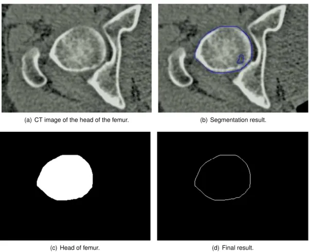
3.9 Segmentation steps of CT images, on the head of the femur. . . 35
3.10 Segmentation steps of CT images, on the head of the femur, with the proposed method. . . 36
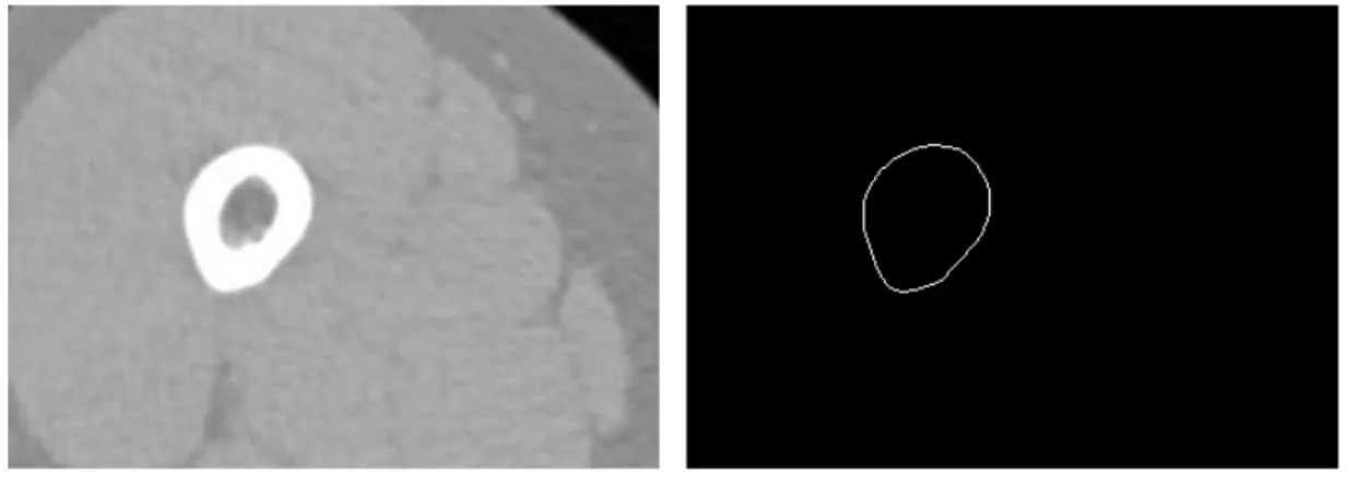
3.11 Segmentation result of CT images in the central part of the bone. . . 37
3.13 Femur Bone Reconstruction, with a high level of transparency (Maximum Intensity
Projection (MIP)). . . 39
3.14 Femur Bone Reconstruction, with highlight bone definitions. . . 40
3.15 Cross section Femur Bone Reconstruction. . . 40
3.16 Volume Rendering performed in Matlab. . . 41
3.17 Surface Rendering performed in Matlab. . . 41
3.18 Results of Visualization a human femur. . . 42
4.1 Example of alignment for local minimum. . . 45
4.2 Registration Results of cow femur bone. . . 47
4.3 Registration Results of human femur. . . 48
5.1 The eye-to-hand experimental setup. . . 61
5.2 Configuration of the markers placed on the end-effector. . . 61
5.3 3D Spiral path used to collect the data for the fuzzy model identification, solid thin line. Task linear trajectory used to test the visual servo control law, dash-dotted thick line. . . 62
5.4 The input data for model identification,δsxy(k + 1), i.e., in the x and y directions. . 63
5.5 The input data for model identification,δsz(k + 1), i.e., in the z direction. . . 64
5.6 The output data,δq(k). For model identification, solid-line, and the estimated fuzzy model output, dash-dotted line. . . 65
5.7 The output data, δq4(k). For model identification, solid-line, and the estimated fuzzy model output, dash-dotted line. . . 65
5.8 Uncalibrated Visual Servo Control Loop. . . 66
5.9 Evolution of the error of the position on the X coordinate. . . 67
5.10 Evolution of the error of the position on the Y coordinate. . . 68
5.11 Evolution of the error of the position on the Z coordinate. . . 68
6.1 Flowchart of the bone tracking based in US images. . . 70
6.2 Region of interest in an US image of a femur phantom. . . 71
6.3 Detail the acquisition of points in the femur head (calibration method 1). . . 73
6.4 Scan of the femur with the ultrasound probe to extract features (calibration method 2). . . 74 6.5 Steps for obtainingCTT
N DItransformation matrix, during calibration process. . . . 75
6.6 Flowchart that describes the calculation of the position and orientation of drilling point in the robot coordinates. . . 77 6.7 Block diagram of the open-loop robot control. . . 78 6.8 Experimental setup. . . 78 6.9 The Real Scenario of the femur phantom, the Us probe, and the drilling point in
the femur head. . . 80 6.10 Experimental apparatus. . . 81 6.11 Results of image processing during the tracking of the femur. . . 82 6.12 The registration process - calibration method 1. 3D Computed Tomography (CT)
point cloud (green). Point cloud of the femur head, before registration (red). Point cloud of the femur head, after registration (black). . . 82 6.13 The registration process - calibration method 2. 3D CT point cloud (green). US
point cloud, before registration (red). US point cloud, after registration (black). . . . 82 6.14 Local registration highlighting - calibration method 1. . . 83 6.15 Local registration highlighting - calibration method 2. . . 83 6.16 The registration process, snapshot from the developed application. Left, before
registration, and right, after registration. . . 84 6.17 On-line local registration, highlighting. US point cloud, before local registration
(red). US point cloud, after local registration (black), performed with Iterative Clos-est Point (ICP) method. . . 85 6.18 On-line local registration. CT point cloud (green). US point cloud, after local
regis-tration (red). US point cloud, after local refinement (black), performed with Coher-ent Point Drift (CPD) method. . . 85 6.19 Bone movements (Red) and robot movements (Blue) during an experiment,
repre-sented in XYZ coordinates. . . 87
Glossary
Computed Tomography
Although also based on the variable absorption of X-rays by different tissues, computed tomography (CT) imaging, also known as ”CAT scanning” (Computerized Axial Tomogra-phy), provides a different form of imaging known as cross-sectional imaging. CT scans of internal organs, bone, soft tissue and blood vessels provide greater clarity and reveal more details than regular X-ray exams. Radiographs are two dimensional representations of three dimensional objects and CT provides images that show all three dimensions.
Hip Resurfacing
Hip Resurfacing arthroplasty is a bone-preserving procedure that helps restore comfort and function to patients’ hips damaged by degenerative joint disease (osteoarthritis rheumatoid arthritis and traumatic arthritis) avascular necrosis or developmental hip dysplasia. It is viewed as an alternative to traditional hip replacements for helping patients return to their active lifestyles.
Total Hip Replacement
Hip replacement surgery involves replacing components of the hip joint with a synthetic implant, to repair the damaged bearing surfaces that are causing pain. In a total hip re-placement both the thigh bone (femur) and the socket are replaced with synthetic implant materials.
Ultrasound
Medical sonography (ultrasonography) is an ultrasound-based diagnostic medical imaging technique that use of high-frequency sound waves to create images of organs and systems within the body. Unlike with an X-ray or CT scan, there is no ionizing radiation exposure with this test. In diagnostic sonography, the ultrasound is usually between 2 and 18 MHz. Higher frequencies provide better quality images, but are more readily absorbed by the skin and other tissue, so they cannot penetrate as deeply as lower frequencies. Lower frequencies can penetrate deeper, but the image quality is inferior.
Acronyms
ANFIS Adaptive Neural Fuzzy Inference Systems
CPD Coherent Point Drift CT Computed Tomography
DICOM Digital Imaging and Communications in Medicine
FMS Fast Marching Segmentation FOV Field of View
GACS Geodesic Active Contour Segmentation
HD Hausdorff Distance HR Hip Resurfacing
ICP Iterative Closest Point
IGSTK Image-Guided Surgery Toolkit
ITK Insight Segmentation and Registration Toolkit
MAP Maximum a Posteriori MHD Modified Hausdorff Distance MIP Maximum Intensity Projection MIS Minimally Invasive Surgery MISO Multiple-input and Single-output
PCL Point Cloud Library
RMSE Root Mean Squared Error ROI Region of Interest
SDS Shape Detection Segmentation SPF Signed Pressure Force
THR Total Hip Replacement
TLSS Threshold Lever Set Segmentation TV Total Variation
UDP User Datagram Protocol US Ultrasound
USB Universal Serial Bus
VTK Visualization Toolkit
List of symbols
α Alpha indicates a balloon force.
βi is the degree of activation of theithrule.
δ Delta indicates an variation. △ △ is the difference operator. ε ε indicates the motion errors.
f f is a collection of fuzzy if-then rules.
J indicates the Jacobian.
λ Lambda is a trade-off parameter.
M ax Max indicates the maximum value.
min min indicates the minimum value.
µAij(xj) is the membership function of the fuzzy setAij.
∇ Nabla indicates the Gradient Operator. norm indicates the norm of a vector.
Ω Omega indicates the region boundary. Pk(zk) is the potential of the data pointzk.
φ Phi indicates the (x,y) contour coordinates. ˙q(k) indicates the robot joint velocities.
q(k) indicates the robot joint positions. Ri is theithrule.
σ Sigma indicates the standard deviation. x indicates the data input vector.
yi indicates the data output vector.
ˆ
y indicates the estimated output, from the model.
Chapter 1
Introduction
H
ealth is the most important asset that the human being can have. The significant improve-ments of the humans life quality, over the years is only achieved because researchers con-stantly seek new solutions and new methods. The use of new technologies to assist medicine al-lows, to improve classical techniques and develop new solutions. These technologies also allows clinicians to improve clinical diagnosis, and assist them in clinical practice, e.g., during surgery. The main objective of the work presented in this thesis is the development of new techniques to assist surgeons, in orthopaedics, while improving accuracy and diminish surgical procedures time. For that, is proposed a new navigation system for a robot-assisted orthopaedic surgery, developed to be used in Hip Resurfacing (HR).The surgical navigation is based on the patient’s own CT imaging data to prepare surgical pro-cedures before operation, i.e., to obtain the desired drilling point. During surgery, to achieve an accurate system to drill the femur head, the robot’s surgical drill and femur movements must be tracked. The surgical drill is tracked through an opto-tracker system, while the femur movements are tracked also using US images. This real-time feedback allows to compensate the femur movements, during the robotic drilling, without incisions in the femur.
1.1
Background and Motivation
The research developed during this thesis addresses a current problem identified by the or-thopaedic surgeons who perform HR surgeries. This problem consists in the amount of time spent, during surgery, to obtain the correct alignment to perform an implant in the femur head, with the current techniques. To find a solution to this problem is the main focus all the research
undertaken in this thesis. This issue was also the motivation to improve the state of the art, and contribute for the developments in this scientific area, improving humans life quality.
An high number of patients with damaged hip have degenerative joint disease (osteoarthritis rheumatoid arthritis and traumatic arthritis) avascular necrosis or developmental hip dysplasia, Berry & Lieberman (2013). In most cases, the patient’s quality of life improves significantly with an hip surgery.
Total Hip Replacement (THR) is one of the most successful orthopaedic interventions used. The femoral head is removed and replaced by a prosthesis. According to the surgeon Derrek McMinn, McMinn (2009), the THR procedure is reasonably successful in elderly, relatively inactive pa-tients. However, replacement hip joints wear out quickly in younger, more active patients, leading to the revision surgery and associated complications.
HR is a bone preserving alternative method to THR, Muirhead-Allwood et al. (2008), which main-tains the anatomical loading situation of the hip almost unaffected. It is viewed as an alternative to traditional THR for helping patients return to their active lifestyles. Observing Figure 1.1, significant differences are noted between the prostheses used in HR and THR. HR is a bone-conserving hip procedure contrary to THR. However, the HR surgical technique is considerably more demanding than THR. Retaining the neck and head of the femur, for instance, makes it much harder for the surgeon to expose the socket. Shaping the femoral head appropriately also takes practice and if the surgeon does that poorly, the patient is far more likely to suffer a femoral neck fracture.
Figure 1.1: Prosthesis used in Hip Resurfacing and Total Hip Replacement.
In the Birmingham Hip Resurfacing surgery (designed in Birmingham by Derrek McMinn), the implant alignment is the most important pre-operative consideration for correct implant position-ing. According to the surgical procedures, described in, Smith&Nephew (2008), and illustrated in figure 1.2, the correct positioning is obtained pre-operatively (step 1), and intra-operatively, the alignment is made from a very time consuming mechanically procedure (step 5), through a align-ment guide (named McMinn Alignalign-ment Guide). A guide wire is inserted when the desired position
1.2. STATE OF THE ART 3
of the alignment guide has been achieved (step 6). The guide wire ensures that the spherical metal cap is positioned correctly on the femoral head. The success of the surgery depends on the correct positioning of the guide wire.
Figure 1.2: smith&nephew, BIRMINGHAM HIP Resurfacing System (Extracted from Smith&Nephew (2008)).
Several studies have identified the malpositioning as a risk factor for femoral neck fracture af-ter HR, Shimmin & Back (2005), Shimmin et al. (2005), Tapaninen et al. (2012), Matharu et al. (2013). Computer navigation systems, are an increasingly alternative to allow accurate place-ment of the femoral implant. Several studies comparing HR procedures performed using me-chanical jigs and computer navigation systems, demonstrate that the computer navigation sys-tems allows more accuracy, Davis et al. (2007), Hodgson et al. (2007), Ganapathi et al. (2009), Bailey et al. (2009). Improve the navigation systems and assist surgeons in the HR procedures is the greatest motivation of this thesis, i.e., to find a robotic solution that increase the accuracy and reduce post-operative complications associated with the technique.
1.2
State of the Art
Increasing advances in robotics have allowed the emergence of new systems dedicated to surgery, which began to be a valid option in surgical procedures. The computer-assisted surgery (CAS), Adams et al. (1990), and particularly the robot-assisted orthopaedic surgery, Kather et al. (2010), Mantwill et al. (2005), improves accuracy and precision of surgical procedures, besides produc-ing more reliable and reproducible outcomes, minimizproduc-ing the invasiveness of surgical procedures and to improve patient outcomes, by reducing complications and improving patient safety, com-pared with conventional orthopaedic techniques.
The use of robots to automate medical tasks increases its reliability, accuracy and are an excel-lent contribution to Minimally Invasive Surgery (MIS). MIS is becoming more and more common
nowadays in hospitals. Surgical procedures are performed through tiny incisions instead of one large opening. Because the incisions are small, patients trend to have quicker recovery times and less discomfort than with conventional surgery. Last thirty years have been marked by the devel-opment of robotic systems for MIS. In 1985 a robot, the PUMA 560, Satava (2002), was used to place a needle for a brain biopsy using CT guidance. Three years later the same machine was used to perform a transurethral resection. In 1987 robotics was used in the first Laparoscopy surgery, a cholescystecotomy. In 1988, the PROBOT, Harris et al. (1997) developed at Imperial College London, was used to perform prostate surgery.
More recently appeared the ZEUS, DaVinci and DLR MIRO surgical systems. The ZEUS robotic surgical system, initially developed in 1995 for endoscopic microsurgery (including general surgery, thoracic surgery, gynaecology, urology), was the robotic system used in the first transatlantic sur-gical intervention performed on a human, in 2001 between New York and Strasbourg, France, at 15000 km of distance, Marescaux et al. (2001). The DaVinci Surgical System enables surgeons to operate through a few tiny incisions with dramatically enhanced vision, precision and con-trol. State-of-the-art DaVinci Surgery helps surgeons to minimize the pain and risk associated with traditional surgery, while increasing the chances for a fast recovery and excellent clinical outcomes. DLR MIRO, Konietschke et al. (2009), Hagn et al. (2008), Matharu et al. (2013), is a compact, slim and lightweight (LWR) robotic system versatile for various existing and future medical robotic procedures. Can be used in orthopaedics to setting holes for bone screws, robot-assisted endoscope guidance and on to the multi-robot concept for (endoscopic) minimal invasive surgery.
In orthopaedics several solutions have emerged, such as ROBODOC, Kazanzides et al. (1995), for the planning and performance of total hip and knee replacement, CASPAR, Beasley (2012), developed for the same purpose of ROBODOC, Acrobot Sculptor, Cobb et al. (2006), Davies
et al. (2007), used in knee surgery, or the RIO robotic arm (MAKOplasty), Pearle et al. (2009),
the latest developed system for orthopaedics. The Robodoc surgical system consisted of the Orthodoc, Paul et al. (1992), pre-surgical planner and the Robodoc as the surgical tool. The Robodoc system comprises a five-axis Sankyo-Seiki industrial robot with a six degree-of-freedom force-sensor. The Orthodoc describes the three-dimensional geometry of the femur from CT data and the geometry of the implant.
The MAKO system consists of the well known general purpose WAM - Whole Arm Manipulator from Barrett Technology, Rooks (2006), for bone deburring, and an optical navigation system consisting of stereo infra-red cameras, and marker arrays attached to the tibia and femur. On the other hand, the Acrobot system uses their special purpose robot manipulator, where the tibia and femur are immobilized with bone clamps which are fixed through small skin incisions.
1.2. STATE OF THE ART 5
The increasing evolution of surgical robotic systems has also been accompanied for signifi-cant evolution in the surgical navigation systems, Stiehl et al. (2007). Of the several systems that have appeared in the market are highlighted the OrthoPilot, Miehlke et al. (2004), (http: //www.orthopilot.com) and the BrainLAB systems, Gumprecht et al. (1999), (https:// www.brainlab.com). Both systems employ markers placed on the femur for tracking the bone movements, Schulz et al. (2007).
Surgical navigation systems allow the surgeon to perform surgical actions in real time using infor-mation conveyed through a virtual world, which consist of computer-generated models of surgical instruments and the virtual representations of the anatomy being operated. Virtual representa-tions can be generated from data obtained through Computer Tomography scans, ultrasound images, amongst others. Image-guided surgical navigation is on the rise in many different ar-eas of medicine, with strong growth in orthopaedic surgery. The use of visual information ob-tained from medical images is widely used in Computer-Assisted Orthopaedic Surgical (CAOS) (www.caos-international.org). CAOS systems are increasingly available, with several commercial and research systems now well-established. These systems assist surgeons in pre-operative planning and simulation, from the obtained bone model, and in intra-pre-operative naviga-tion, using tracking systems with fiducial markers attached to the patient bone, and in the robotic execution of the surgical procedure. From the fiducial markers the position and orientation of the bone, in the intra-operative scenario, relative to the robot frame is obtained in the state-of-the-art systems, e.g., the BrainLab System or Orthopilot.
The incisions performed to place these markers, can leave serious injury to the patient. There are many cases of complaints of pain at the implant site after Surgery. Studies on the patients reported persistent severe pain at the site of pin implantation, after surgery, caused by the injuries to the nerves, result of the fiducial markers’s implants, Nogler et al. (2001).
Recently, much scientific research work has been developed, with the purpose of eliminating fiducial markers in orthopaedic surgery, Amiot & Poulin (2004), Nabeyama et al. (2004), and the main guidelines of research focuses on the use of intra-operative US and pre-operative CT to pro-vide real time surgical guidance. In Beitzel et al. (2012), it is presented a semi-automatic bone detection approach for US via registration with CT datasets pre-operatively acquired. The CT data is used to create a patient-specific bone model, and rigid transformation from US to CT are estimate by ICP algorithm, from a initializing of three points in the datasets. The three correspon-dence points, define the principal axis and orientation of the bone in both modalities. Moghari & Abolmaesumi (2007), propose a point-based registration algorithm based on unscented Kalman filter (UKF) to estimate the rigid transformation parameters between the bone surfaces obtained from US and CT data, less sensitive to outliers compared with ICP. Both methods are based on
features of the datasets (feature-based), but there are also methods that use the image inten-sity information (inteninten-sity-based) directly in order to avoid extraction of bone surfaces. Penney
et al. (2006), used normalized cross-correlation as a similarity metric for registering CT and US
images. Prior to registration, both datasets were converted to bone probability images using gra-dient, bone intensity and US shadowing artefact information. More recently, in Hacihaliloglu et al. (2013), is proposed a rigid registration method where the translation parameters are estimated from the projections of local phase volumes in frequency domain. Bone surfaces were automati-cally extracted directly from 3D US and CT volumes based on 3D local image features calculated using 3D Log-Gabor filter.
Common drawbacks of these systems reside in the invasiveness of the bone tracking method. The innovative contribution of this thesis emerge to overcome this drawback: a tracking system for the femur which uses an optically tracked ultrasound probe, eliminating the extra skin and bone incisions for marker placement as well as the inaccuracies associated with their placement. After its incipient experiments, ultrasound based visual servoing has recently gained new interest due to the establishment of visual servoing. Initial works consisted in the use of robot arms which manipulated an ultrasound probe for medical diagnoses, Abolmaesumi et al. (2002), Krupa & Chaumette (2006). The use of ultrasound also found its way into orthopaedics as a non-invasive radiation-free navigation system for surgeon operated, interventions, Chen & Ellis (2005). This is particularly valuable when the bones to be operated are so small, that it is not possible to attach heavy tracking targets onto them. For interventions cooperated by robot arms, effective appli-cations using ultrasound guidance are not yet available, but an intense race involving research centers and industry is currently taking place.
Guiding a robot in positioning tasks through visual information using uncalibrated visual servoing systems is a very active research topic due to the complexity of real applications and workspace scenarios such as an operating room. The operating room can unpredictably change during a HR surgery, causing calibration errors. In Gonc¸alves et al. (2008), uncalibrated visual servoing was proposed, where the inverse system Jacobean was estimated on-line, thus immune to camera miss-calibration. It presents a very promising solution for the operating room, where it is also desired to minimize calibration time. Furthermore, this approach will give added robustness to a medical setting where the environment is calibrated, but redundancy is necessary for safety reasons. This work has been further extended to a more general case in, Gonc¸alves & Pinto (2008), where the uncalibrated model can evolve during the tasks to be performed. In Gonc¸alves & Fernandes (2008), tools for ultrasound based 3D Bone model reconstruction, registration and visualization are presented, which are currently being developed by the research team, in order to introduce ultrasound feedback in the visual control loop. In Gonc¸alves et al. (2009), was
1.3. HIPROB PROJECT 7
proposed and approach to obtain the position and orientation of a bone based in it’s 3D model obtained from Computed Tomography images (in the preoperative scenario) and the registration of ecographic images to it (in the intra-operative scenario).
1.3
HipRob project
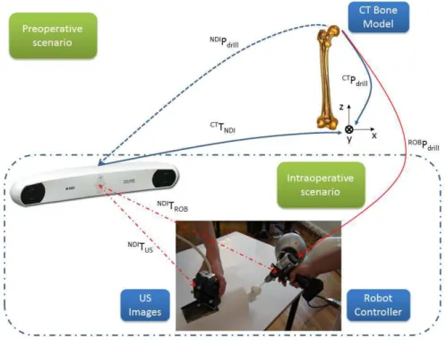
The current thesis was developed in the scope of the HipRob Project, (http://www.echord. info/wikis/website/hiprob), it emerges from the desire to develop a system that helps surgeons to perform HR prosthesis surgery. It is designed to aid surgeon to perform the initial drilling, necessary for guide wire implant. A co-manipulation robotic solution for HR surgery based on variable impedance control for physical surgeon-robot interaction will be developed. US images are used for non-invasive real-time bone tracking. The innovative co-manipulation setting to the medical gesture brings together the higher geometric accuracy and precision of the robot manipulator with the higher sensibility and decision making capability of the surgeon when applying force, thus resulting in clear benefits for patients, medical doctors and hospitals. For navigation, the system, during surgery, acquires a 3D US bone surface from a sequence of US images. This bone surface will then be registered to the pre-operative bone model, for a precise knowledge of the bone position and orientation. This registration is performed in two steps. The first, a global registration before the surgical procedure, to exactly register the bone. The second is to locally register the femur, which is faster and more suitable for tracking the bone movements. The measured bone movement is used by the robot manipulator to update its drilling position and orientation. Figure 1.3 shows an overview of the HipRob navigation system.
The avoidance of fiducial markers implies that the US probe is referenced to the optical mea-surement system (NDI - Polaris), (http://www.ndigital.com/medical/). This referencing is made by placing a marker in the US probe. From this moment, also the images and features are referenced to the tracker. The pose of the robot end-effector also has to be referenced by the Navigation system to inform the robot controller of its location. The ideal drilling point, is obtained pre-operatively in the CT reference frame. Inside the operating room, a initial calibration (CTT
N DI) between the tracker (NDI) and CT is needed to localize the femur. After calibration, the
main goal consists in to determine at each instant, the drilling point in the robot reference frame (ROBP
Figure 1.3: Overview of the hardware setup and frames transformations of HipRob navigation system.
1.4
Objectives
In the doctoral plan three types of objectives were proposed, technical, sociological and multidis-ciplinary. First, are presented the technical objectives related to specific points of the scientific work which are outlined below:
• Position Based Visual Control of a robotic manipulator, using a high speed 3D optical track-ing device - Polaris;
• Kinematic modelling between the imaging sensing devices, bone and robotic manipulator; • Integration of the 3D Bone model based on CT in the navigation system;
• Ultrasound Based Visual Control of a robotic manipulator; • Development of a laboratory prototype for experimental testing;
Secondly, are the sociological objectives related to the human factors of the project such as the improvement in people’s health, particularly in the rehabilitation of patients with joint or bone related pathologies, and the benefits of less invasive surgeries and higher precision procedures. An example is the hip resurfacing surgical procedure stated in the State of the Art.
1.5. CONTRIBUTIONS 9
Finally there are the multidisciplinary objectives: the bringing together of two disciplines, Me-chanical Engineering and orthopaedics, in order to improve bone related surgery. The traditional language used in both fields is different, and in this work will have to be brought together produc-ing a common language that both fields may understand.
1.5
Contributions
During the development of this thesis some important contributions have been made:
• Two solutions are proposed to acquire, intra-operatively, US images spatially located. The first is a freehand system, where it is used the NDI Polaris opto-tracker to measure the po-sition and orientation of the US probe. The Image-Guided Surgery Toolkit (IGSTK) toolkit is used to acquire and synchronize the images with the Polaris. The second solution is a non-freehand system, where the US probe is placed on the end-effector of an anthropomorphic robot arm. The robot is responsible to move the US probe along the leg and give a spatial location for each US slice of the bone.
• A new region-based approach for US images segmentation based on an existing algorithm, was proposed. Concretely was added a regulation term to block the contour’s evolution to far from the initialization region, identifying only the desired object. Was also added a new condition to stop the segmentation method, and was used the output of previous segmentation as a mask to the next image, in the segmentation process. Both contributions improve significantly the processing times.
• Were developed and implemented some software tools for image segmentation, registration and visualization, useful both for surgical planning as for the intra-operative procedures.
• A new approach for US based robot navigation was developed. This approach uses regis-tration algorithms to identify bone movements intra-operatively and updates at each instant the desired target’s position and orientation. This approach is used to close the control loop for robotic motion compensation, using the 3D point clouds extracted from the contours of US images.
1.6
Publications
1.6.1
Book Chapters
1. Pedro M. B. Torres, Paulo J. S. Gonc¸alves, “Ultrasound Imaging for Robotic Orthopedic Surgery: A Survey”, Computer- Assisted Surgery: New Developments, Applications and Potential Hazards, Xiaojun Chen, (Ed.), Surgery - Procedures, Complications, and Results Series, Nova Publishers, 2015, ISBN: 978-1-63463-811-1;
2. P.J.S. Gonc¸alves, P.M.B. Torres, ”Visual Control of Robotic Manipulators: Fundamentals”, Robotics: State of the Art and Future Trends, L. Legnani, I. Fassi, (Eds.), Computer Sci-ence, Technology and Applications Series, Nova Publishers, 2012, ISBN: 978-1-62100-403-5;
1.6.2
Papers in Refereed International Journals
1. P.J.S. Gonc¸alves, P.M.B. Torres, F. Santos, R. Antonio, N. Catarino, J.M.M. Martins (2015) A Vision System for Robotic Ultrasound Guided Orthopaedic Surgery. Journal of Intelligent and Robotic Systems 77 (2) pp. 327-339. Springer Netherlands;
2. P. M. B. Torres, P. J. S. Gonc¸alves , J. M. M. Martins, ”3D Reconstruction and Visualization of Femur Bone Structures”, Romanian Review Precision Mechanics, Optics & Mechatron-ics, nr. 41, pp. 51-56, 2012;
3. P. M. B. Torres, P. J. S. Gonc¸alves , J. M. M. Martins, ”Robot Calibration for Precise Ultra-sound Image Acquisition”, Romanian Review Precision Mechanics, Optics & Mechatronics, nr. 40, pp. 129-134, 2011;
4. P. J. S. Gonc¸alves, P. M. B. Torres, ”Extracting Bone Contours in Ultrasound Images: En-ergetic versus Probabilistic Methods”, Romanian Review Precision Mechanics, Optics & Mechatronics, nr. 37, pp. 105-110, 2010;
5. P. J. S. Gonc¸alves, M. V. Carvalho, D. F. A. Mateus, P.M.B. Torres, ”Registo de Imagens Ecogr ´aficas com Modelo 3D de Ossos aplicac¸ ˜ao ao f ´emur”, RISTI Revista Ib ´erica de Sistemas e Tecnologias de Informac¸ ˜ao, N.4, 12/2009, ISSN: 1646-9895, pp. 43-56;
1.6. PUBLICATIONS 11
1.6.3
Papers in Proceedings of International Conferences
1. P.M.B. Torres, P.J.S. Gonc¸alves, J.M.M. Martins, ”New Approach to the Open Loop Control for Surgical Robots Navigation”, Controlo 2014, 11th Portuguese Conference on Automatic Control, Porto, Portugal, 21-23 July 2014;
2. P. J. S. Gonc¸alves, P. M. B. Torres, J. M. M. Martins, ”Towards a Software Tool for Ul-trasound Guided Robotic Hip Resurfacing Surgery”, ECHORD workshop in (IROS 2012), IEEE/RSJ International Conference on Intelligent Robots and Systems, Vilamoura, Portu-gal, 7-12 October 2012;
3. P. M. B. Torres, J. M. Sanches, P. J. S. Gonc¸alves, J. M. M. Martins, ”3D femur recon-struction using a robotized ultrasound probe,” Biomedical Robotics and Biomechatronics (BioRob), 2012 4th IEEE RAS & EMBS International Conference on , vol., no., pp.884-888, Rome, Italy, 24-27 June 2012, doi: 10.1109/BioRob.2012.6290782;
4. P. M. B. Torres, P. J. S. Gonc¸alves, J. M. M. Martins, ”Bone Registration using a Robotic Ultrasound Probe”, International Conference VipIMAGE 2011 - III ECCOMAS Thematic Conference on Computational Vision and Medical Image Processing, Olh ˜ao, Portugal, 12-14 October 2011;
5. P. M. B. Torres, P. J. S. Gonc¸alves, J. M. M. Martins, ”3-D Surface Registration of Ul-trasound to CT-Bone Images”, Euromedia 2011, Workshop on Medical Imaging Systems, London, UK, 18-20 April 2011;
6. P. J. S. Gonc¸alves, Pedro M.B. Torres, ”Registration of Bone Ultrasound Images to CT Based 3D Bone Models ”,6th International Conference on Technology and Medical Sci-ences, Porto, Portugal, 21-23 October 2010;
7. P. M. B. Torres, P. J. S. Gonc¸alves, J. R. Caldas Pinto, ”Uncalibrated Stereo Visual Servo Control Using Fuzzy Models ”, Controlo’ 2010, 9th Portuguese Conference on Automatic Control, Coimbra, Portugal, 8-10 September 2010;
1.6.4
Papers in Proceedings of National Conferences
1. P.J.S. Gonc¸alves, P.M.B. Torres, J.M.M. Martins, ”Towards a Software Tool for Ultrasound Guided Robotic Hip Resurfacing Surgery”, ACM Symposium on Applied Computing 2013, Intelligent Robots track, Coimbra, Portugal, March 2013;
2. Pedro M. B. Torres, J. Miguel Sanches, Paulo J. S. Gonc¸alves, Jorge M. M. Martins, ”Robotic 3D Ultrasound”, Proceedings of RECPAD 2012, 18th Portuguese Conference on Pattern Recognition, Coimbra, Portugal, 26th October 2012;
3. Ruben Ant ´onio, P.J.S. Gonc¸alves, P.M.B. Torres, ”Simulation of Ultrasound Guided Robotic Surgery with MORSE”, Proceedings of RECPAD 2012, 18th Portuguese Conference on Pattern Recognition, Coimbra, Portugal, 26th October 2012;
4. F ´abio Santos, P.J.S. Gonc¸alves, P.M.B. Torres, ”3D Point Cloud Registration of the Femoral Bone, using the Point Cloud Library”, Proceedings of RECPAD 2012, 18th Portuguese Conference on Pattern Recognition, Coimbra, Portugal, 26th October 2012;
5. Nuno M.M. Catarino, P.J.S. Gonc¸alves, P.M.B. Torres, ”Bone Contour Segmentation from US Images - A Comparative Study”, Proceedings of RECPAD 2012, 18th Portuguese Con-ference on Pattern Recognition, Coimbra, Portugal, 26th October 2012;
6. P. J. S. Gonc¸alves, P. M. B. Torres, ”Femur Contour Extraction using Energetic and Prob-abilistic Models”, Proceedings of RECPAD 2010, 16th Portuguese Conference on Pattern Recognition, Vila Real, Portugal, 29th October 2010;
7. P. J. S. Gonc¸alves, P. M. B. Torres, ”The ICP Method Applied to Register US Images to 3D Bone Models”, Proceedings of RECPAD 2010, 16th Portuguese Conference on Pattern Recognition, Vila Real, Portugal, 29th October 2010;
1.7
Outline of the Thesis
The remainder of this thesis is organized as follows: In the following chapter, the CT and US image acquisition procedures, are presented. The chapter describe the architecture of the free-hand US acquisition system based on the optical tracker NDI Polaris Spectra and on the IGSTK toolkit. Is also described the non-freehand system for US image acquisition with a robot.
Chapter 3 presents the image processing tasks performed to extract the 3D point clouds from calibrated US and CT datasets. It is also described a new approach for medical imaging seg-mentation, that improves the computational speed. The last part of the chapter describes the 3D reconstruction and visualisation procedures form CT data, used in the pre-operative scenario. In chapter 4 are presented the, multimodal point set registration procedures to register US with CT data. The classical ICP is described as well as a more recent approach called CPD method. These methods were compared regarding speed and accuracy, to justify the application in the final experimental system.
1.7. OUTLINE OF THE THESIS 13
Chapter 5 describes the experiments performed with visual servoing to control a robot manipu-lator. The Visual Control is addressed when the sensing information, need to close the loop, is obtained from image features.
Chapter 6 describes the integration of all tasks previously presented in order to design a new approach for surgical navigation. The navigation is entirely based on the information extracted from image information. In real-time, the US point sets are registered with the model, constructed from CT, to obtain the femur displacements during surgery. In the chapter is also presented the experiments performed in a human femur phantom, which validate the proposed approaches in this thesis.
The last chapter (Chapter 7) presents the general conclusions achieved during the thesis devel-opment and proposals for future work.
Chapter 2
Image Acquisition
T
his chapter describes the important aspects of image acquisition, both ultrasound and CT. It is a background chapter, which describes the details of the acquisitions that will be subsequently considered in chapter 3, where is reported the image processing.2.1
Ultrasound Image Acquisition
Ultrasound imaging provides a non-invasive and convenient technology that has recently bene-fited from the development of three-dimensional (3D) reconstruction techniques. Volume recon-struction of ultrasound images can be performed directly with 3D probes, more expensive, or by spatial measurement systems coupled to the conventional 2D ultrasound probe. Freehand and non freehand US acquisition systems, were developed in this work to perform 3D reconstruction across US images acquired in B-mode trough 2D US probes.
2.1.1
Freehand Ultrasound Acquisition System
In this subsection is presented a Freehand Acquisition System developed for acquisition of US images, properly referenced. This module is based on IGSTK (http://www.igstk.org/), a free open source C++ toolkit, that provides a framework for rapid prototyping of customized image-guided surgical applications. The toolkit provides a set of components common to general purpose navigation systems, such as interface with tracking systems, image registration and visualization though the Insight Segmentation and Registration Toolkit (ITK) (http://www.itk. org/) and Visualization Toolkit (VTK) (http://www.vtk.org/). For the acquisition system
proposed in this thesis the integration of the Open Computer Vision library, OpenCV (http: //opencv.org/), was also done to allow ultrasound image acquisition and processing from the US probe, through an Universal Serial Bus (USB) video capture. NDI Polaris Spectra is the sensor used to measure the pose of passive targets. Three different markers are used, one attached to the robot end-effector in order to measure the passive targets pose, presented in left side of figure 2.2 (ref. 8700339), other, on the US probe to measure the pixels 3D position, presented in right side of figure 2.2 (ref. 8700449), and the other free-hand (ref. 8700340), figure 2.2 c), to be used in marking some points of interest, e.g., perform palpation of the femur head. Each point in US images can be referenced to the NDI frame (N DIP ), through the equation 1.
N DIP =N DI T
M k×M kTpr×prTi×iP (u, v) (1)
According to figure 2.1,N DIT
M k, represents the relationship between passive markers and
Po-laris system, M kT
pr, represents the relationship between the US probe extremity and Marker,
prT
icorresponds to the relationship between the image plane and US probe, and finally,iP (u, v)
represents a point in the US image. The transformationsM kT
prandprTi, depicted in figure 2.1,
are previously calibrated off-line.
To obtain the marker’s position and orientation, the igstk::Transform class was used. This class represents relative positions and orientations in 3D space. It is intended to be used for posi-tioning objects in the scene, since it is a means of communication between trackers and spa-tial objects. The Translational component is obtained from the function ” GetTranslation() ” (igstk::Transform::GetTranslation()), and Rotational component is obtained from the function ”
GetRotation() ” (igstk::Transform::GetRotation()). 3D position of each point is obtained in [mm],
and orientation is provided in quaternion, format [Qx, Qy, Qz, Qw], or in the form of rotation ma-trix. With the position and orientation components is defined the homogeneous transformation matrix that relates the pose of the marker in 3D space, referenced in the Polaris frame, according to the equation 2. N DIT M k= N DIR3×3 N DIt3×1 03×3 1 (2)
To obtain the matrix that relates the center of the US probe, to the passive marker reference frame, it is important to know the translation offsets in X (px1), Y (py1) and Z (pz1). These offsets
2.1. ULTRASOUND IMAGE ACQUISITION 17
Figure 2.1: Optical Tracking System and coordinate frames used in image acquisition process.
are obtained thought metric measurements, and confirmed using the free-hand marker. The matrix in equation 3, represents the calibration matrix, obtained, where px1, py1 and pz1 are expressed in [mm]. The rotation component is defined by the identity matrix, because the US probe is aligned with the marker and there is no rotation component.
M kT pr= 1 0 0 px1 0 1 0 py1 0 0 1 pz1 0 0 0 1 = 1 0 0 −35, 0000 0 1 0 65, 9800 0 0 1 41, 4878 0 0 0 1 (3) Equation 4 (prT
(a) Marker 8700339 layout. (b) Marker 8700449 layout.
(c) Marker 8700340 layout.
Figure 2.2: Tools Specifications, extracted from the Polaris Spectra Tool Kit Guide.
prT i = 0 0 1 0 0 1 0 0 −1 0 0 0 0 0 0 1 (4)
P (u, v) represents any point in US image, ui and vi are the pixel coordinates and u0, the
co-ordinate of the center, obtained from calibration. Sx and Sy are the scale factors, two of the
US imaging device intrinsic parameters, obtained from calibration. CIRS Ultrasound Calibra-tion Phantom, model 555 (http://www.cirsinc.com) was used to obtain these scale factors. This Phantom is a cube with a small egg and a large egg. There are two scanning surfaces and the targets are centred within the background material. Knowing the dimensions of each egg, it is possible to obtain the relationshippixels/mm for each level of depth of the US equipment and calculate the scale factors.
2.1. ULTRASOUND IMAGE ACQUISITION 19 P (u, v) = Sx(ui− u0) Sy(vi) 0 1 (5)
2.1.2
Non Freehand Ultrasound Acquisition System
A significant amount of scientific work has been produced in order to acquire US images with the aid of automatic mechanisms, such as robots, Abolmaesumi et al. (2000), Mebarki et al. (2010). The concept of Ultrasound Visual Servoing, Mebarki et al. (2008), Bachta & Krupa (2006), is a theme that has shown good results in the control of probe positioning, with practical application in different areas, helping technicians and automating the diagnosis based on ultrasound images. This subsection presents a non freehand US acquisition system, where the probe displacement and position are accurately controlled by an anthropomorphic robot. The aim of this system is to acquire a sequence of 2D parallel cross-sections evenly spaced along the displacement direction in order to perform an accurate 3D reconstruction of the femur. The robotic system used, consists of an Eurobtec IR52C robot manipulator. The probe is placed in the end effector of the robot, responsible for positioning the probe in contact with the femur. The images were acquired and the femur scanned with the best possible coupling at a constant speed. In the preparation of each experiment is necessary to define the pose of the robot that guarantees the best coupling between the probe and the femur, without hurting the patient. Initial and final points of acquisition must be defined, to perform trajectory planning along the femur. Whenever possible, trying to make linear trajectories. The estimation of the hand-eye and the robot-world transformations, to know the positioning of the probe at every moment, is an important point of this work. These estimations allow to perform a precise three-dimensional reconstruction of the bone. Each point in US images can be referenced to the world frame (wP ), through the equation 6.
wP =wT
b×bTe×eTpr×prTi×iP (u, v) (6)
According to figure 2.3(a), wT
b represents the relationship between the base of the robot and
the position coordinates in the world frame (equation 7) , bT
eis the relation between the robot
end-effector and its base, computed from the robot kinematics,eT
prrepresents the relationship
between the US probe extremity and the robot end-effector (equation 8),prT
relationship between the image plane and US probe (equation 4), and finally,iP (u, v) represents
a point in the US images, the same matrix used in the freehand system, equation 5.
(a) Robot with frames used in calibration. (b) Acquisition Details in a human femur.
Figure 2.3: Robotic 3D US system.
wT b= 0 0 1 0 0 1 0 0 0 −1 0 pz 0 0 0 1 (7)
wherepz corresponds to robot movement, in mm, along to its linear axis.
eT pr= 0 1 0 0 0 0 1 0 1 0 0 135 0 0 0 1 (8)
With this system, various tests were performed in the laboratory, first with a cow femur bone within a tank of water and after in human femurs. Figure 2.3(a) shows the experimental apparatus during the scan of a cow femur and in Figure 2.3(b), where it can be seen in detail an acquisition to a human femur.
2.2. CT IMAGE ACQUISITION 21
2.2
CT Image Acquisition
Two acquisitions of CT images were performed during the thesis, first with a cow femur bone to preliminary tests and second with a human femur. Both acquisitions were performed with a Siemens SOMATOM Sensation 16 CT scanner in a medical imaging center, with a slice thickness of 0.75 [mm] and a spacial resolution of 512 × 512 pixels. The acquisition of human femur was performed with a Field of View (FOV) of 185 [mm], pitch of 0.5 and reconstruction interval of 0.1 [mm]. In this acquisition, 4913 images were stored in Digital Imaging and Communications in Medicine (DICOM) standard format, which is equivalent to491.3 [mm] (4913 × 0.1) of femur. This specifications are important to determine the reconstruction parameters. FOV represents the maximum size of the object under study, in this case the femur. Since the image matrix size is512 × 512, the pixel size (ps), is obtained from the relation between FOV and matrix size (M), according equation 9.
ps = F OV M =
185
Chapter 3
Image Processing
U
ltrasound and CT images of femur can be used to eliminate the bone incisions to attach the fiducial markers in orthopaedic surgery, and to extract the position and orientation of the bone for robotic navigation during the surgical procedure. For that, image processing is an important task in this work. This chapter presents the US and CT image processing steps for identify the bone contours from images and extract the point clouds for the registration process presented in chapter 4.3.1
Ultrasound Image Processing and Segmentation
Since the bone is a rigid anatomical structure, ultrasound signals are reflected, and the image only captures the top layer of the bone. Processing this type of images is a challenging task, since images are very noisy and blurred. The image quality decreases severely when approaching the knee, because there is less muscle mass. When the bone gets closer to the probe, the US reflections are more intense. Other issue is the difficulty of coupling the probe to the knee, reducing the image quality.
Image Denoising was used to remove the noise that degrades the images, e.g., Speckle, the most common noise in US images. The objective is to smooth homogeneous areas while preserving the contours without distorting the images. The algorithm used is based on the Maximum a Posteriori (MAP) criterion with a Total Variation (TV) edge-preserving Gibbs prior. The method is formulated as an optimization task that is solved by the Sylvester equation, developed by Sanches et al. (2008).
To extract bone contours in all images, several tests were performed with energetic and proba-bilistic methods, Gonc¸alves & Torres (2010), and Catarino et al. (2012). However it was extremely difficult to extract the bone with significant precision. In 2010, Zhang et al. (2010), presented an Active Contour method, that conjugates the benefits of edge-based methods (Geometric Active Contour models, Sandhu et al. (2008)) and region-based methods (Chan-Vese algorithm, Chan & Vese (2001)). Methods based on the contour (edge-based), have some limitations and fail when the initialization is far from the object. The tests performed with this type of algorithms demon-strates that less careful initialization, results in a poor bone segmentation. With region-based methods, as the Chan-Vese and related, the statistical information inside and outside the contour is used to control its evolution, making it less sensitive to the noise. This method presents good results even for images with weak or blurred contours, besides being less sensitive to initializa-tion. The method was applied to an image, after Denoising, but several objects were identified in the image beyond the region of interest, i.e., the bone. In fact, several regions in the images with pixel intensity similar to the bone, leading to similar values for known statistical metrics, even if the initialization is a square around the bone contour of interest.
To obtain accurate results for the problem at hand, it is necessary to understand where is the bone region and apply a regulation term to the forces function, that control the contour evolution, and lock evolutions far from the original mask. The next subsection describes the algorithm implemented and new contributions to segment ultrasound images of the femur.
3.1.1
Segmentation Method
The method proposed by Zhang et al. (2010), uses the statistical information inside and outside the contour to construct a region-based Signed Pressure Force (SPF) function in order to define the contour, described in equation 10. The signed pressure force modulates the signs of the pressure forces inside and outside the region of interest so that the contour shrinks when outside the object, or expands when inside the object.
spf (I(u, v)) = I(u, v) − c1+c2 2 max(|I(u, v) −c1+c2 2 |) (10)
whereI(u, v) is the image with (u, v) coordinate pixels. c1 andc2are two constants which are
the average intensities inside and outside the contour, respectively, obtained from minimization of Chan-Vese energy function defined by equation 11.
3.1. ULTRASOUND IMAGE PROCESSING AND SEGMENTATION 25 ECV = λ1 Z inside(C) |I(u, v) − c1|2dudv + λ2 Z outside(C) |I(u, v) − c2|2dudv (11)
λ are fixed parameters, determined by the user.
c1(φ) = R ΩI(u, v) · H(φ)dudvR ΩH(φ)dudv (12) c2(φ) = R ΩI(u, v) · (1 − H(φ))dudvR Ω(1 − H(φ))dudv (13)
H(φ) is the Heaviside function of the contour coordinates φ and Ω the region boundary. The author also proposes a new level set formulation to extract the contour, formulated by equation 14 and explained in Zhang et al. (2010).
∂φ
∂t = spf (I(u, v)) · α | ∇φ | (14) whereα is the balloon force, which controls the contour shrinking or expanding, and ∇ is the gradient operator. The method present a high potential to segment the bone in US images, but the low contrast between regions sometimes leads to errors and the segmentation of other objects in image.
It is important to define a regulation term to the forces function, that control the contour, and lock evolutions far from the original mask. Furthermore a new method to stop the contour evolution was implemented. The intensities inside and outside the contour are controlled to maximize the relations between them and the contour evolution stops only when the parameters converge, eliminating the number of iterations to define when the algorithm stops, used by Zhang et al. (2010). With this approach the processing time and the segmentation precision was improved, since the images are different, e.g. one image may need 50 iterations to converge while another requires only 5 iterations. The method converge when:
This means that, as from a given instant the values ofc1andc2tend to stabilize and the contour
presents no evolution, the algorithm can be stopped because it will not change the contour, i.e. the method converged. So it was improved the processing times and accuracy of segmentation.
Algorithm
1. Initialization (φ(u, v), t = 0): Define a square in the region of interest, where the values inside areφ(u, v) = 1 and outside φ(u, v) = −1;
2. Computec1(φ) and c2(φ), according equations 12 and 13;
3. Evolve the level set function according equation 14 4. Letφ(u, v) = 1 if φ(u, v) > 0; otherwise φ(u, v) = −1
5. Regularize the level set function with a Gaussian filter: φ(u, v) = φ(u, v) ∗ Gσ
6. If method converge (condition term, 15)φ(u, v) represents the image segmentation; Else, return to the step 2;
End Algorithm
φ(u, v) = φ(u, v) ∗ Gσ is the convolution of local segmentation with a Gaussian filter, where the
standard deviation (σ) influences the sensitivity of the algorithm for the noise. Flowchart of figure 3.1, helps to understand the method used to segment all US images.
3.1.2
Image Processing and Segmentation Results
Many experiments were performed with freehand and non freehand systems described in chapter 2, first with a cow femur bone in a water tank and after in human femurs. This subsection presents the experimental image processing and segmentation results, obtained from the processing of 245 US images of a human femur, acquired with the non freehand system, but with the spatial location of the probe performed by the Polaris optical tracking system. In this experiment a girl’s leg was scanned, on the central part of the leg from the hip to the knee with an ALOKA prosound 2 echograph with a5 M Hz probe. All images were acquired with a resolution of 720 × 576 pixels with an image plane of6 [cm] (R06 - mean that one scale division, on image is equal to 0.5 [cm]), and a probe frequency of7.5 M Hz. Figure 3.2 a), represents an US image of the central part of femur.
The first step is to identify the Region of Interest (ROI) and clean the images with the Denoising method developed by Sanches et al. (2008). Figure 3.2(b) shows the region of interest defined
3.1. ULTRASOUND IMAGE PROCESSING AND SEGMENTATION 27 Start (1) Initialization (2) ComputeC1andC2 (3) Evolve level set equation (4) Local Segmentation (5) Regularize the level set funcion
Converged?
END
no
yes
and the result after applying the Denoising algorithm for image 3.2(a). The processing time in the images cleaning is relatively high, an average of3.8181 seconds per ROI of image, however facilitates the segmentation process and increases its accuracy. Previous laboratory tests without applying this cleaning method show that it is extremely difficult to achieve bone segmentation in an automated way.
(a) US Bone Image. (b) Denoising Result, in the region of interest.
Figure 3.2: Ultrasound image before and after denoising process.
The graph in Figure 3.3 represents the evolution processing time, for cleaning all 245 images. As can be seen, the first image requires more time to converge. For the next images the processing time is significantly lower, because the algorithm use information from previous result, as input to the following images.
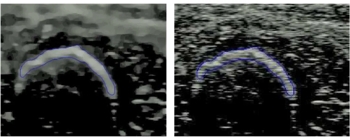
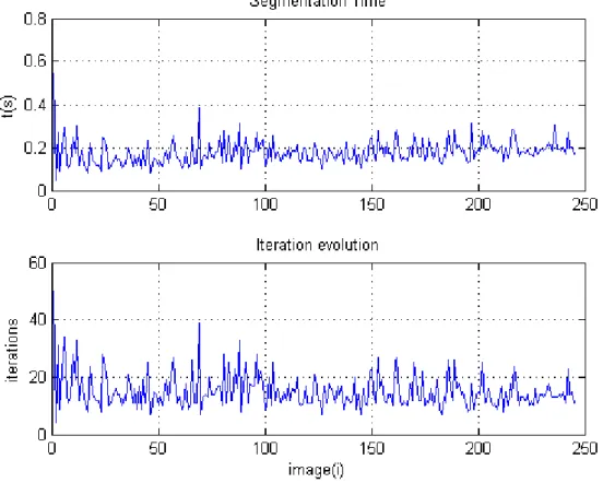
After cleaning, all the images are segmented using the method described in subsection 3.1.1. To reduce segmentation processing time of a set of images, the output result of a previous image is the input mask to the next image. Figure 3.4(a) shows the segmentation result of the image with index 100 (figure 3.2(a)). The initialization is performed in the image with index 1. To evaluate the results, the contour extracted is overlayed on the original image as seen in Figure 3.4(b). The bone was identified, despite the segmentation being performed in blurred images. Similar results are obtained to all images in the dataset. On average,0.1779 seconds and 15.1265 iterations are needed to segment each image in the dataset, with this method.
The graph in Figure 3.5 represents the segmentation time and the number of iterations performed by the method to segment all 245 images. All experiments were performed in MATLAB, with an Intel Core 2 Duo, 2.27 GHz computer, with 4 GB RAM.
3.1. ULTRASOUND IMAGE PROCESSING AND SEGMENTATION 29 0 50 100 150 200 250 3.7 3.8 3.9 4 4.1 4.2 4.3 4.4 4.5
Processing time during Denoising
image(i)
t(s)
Figure 3.3: Evolution of Processing time during Denoising.
(a) Bone segmentation. (b) Bone identification in the original image.
3.1. ULTRASOUND IMAGE PROCESSING AND SEGMENTATION 31
were performed with a cow femur, a steak and a needle. As can seen in figure 3.6, when a needle penetrates the steak on the bone, does not penetrates the stain, finding the bone in the upper surface of image. Therefore, only the upper surface of the femur (open contour) is extracted from images, after segmentation.
Figure 3.6: Surface detection in US images through a needle.
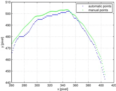
Root Mean Squared Error (RMSE) (equation 16) and Mahalanobis distance (MD) (equation 17)
were used to analyse the performance of the segmentation method, when applied to the upper contours of all images.
RM SE(i) = r P (vg − ve)2 n (16) MD(i) = q (vg − µg)TS−1(ve − µe) (17)
vg are the ground-truth values (obtained manually), ve are the estimated values (obtained thought segmentation) andn is the number of points in each image contour. Since vg and ve can have different sizes, a cubic spline was used to interpolate both contours, allowing them to have the same size.