JOURNAL OF APPLIED INSTRUMENTATION AND CONTROL 1
Abstract — This paper presents a 1 kHz SVM-FOC (Space Vector Modulation with Field Oriented Control) drive system for a PMSM (Permanent Magnet Synchronous Motor), using different control strategies. Such strategies are internal model and frequency response designed PI (Proportional-Integral) controllers and a multivariable MPC (Model Predictive Control) controller using a state-space prediction model. This MPC method becomes interesting for improving the closed-loop speed frequency response, since it results in a cascade-free controller. The performance of each controller was evaluated in a qualitative manner through reference tracking simulations and quantitatively by load torque and speed reference AC sweeps, generating dynamic stiffness curves and Bode diagrams. Results show that the MPC approach is useful for enabling fast dynamic responses with the reduced switching frequency, which reduces the drive system cost and improves its efficiency.
Index Terms— MPC, FOC, PMSM, Multivariable Control, Frequency Response.
Resumo — Este artigo apresenta um sistema de acionamento para um motor síncrono de ímãs permanentes (PMSM) com Controle por Orientação de Campo e Modulação por Vetores Espaciais (SVM-FOC) de 1 kHz usando diferentes estratégias de controle. Tais estratégias são controle Proporcional-Integral (PI) de modelo interno projetado através da resposta em frequência e um Controlador Preditivo (MPC) multivariável com modelo de predição no espaço de estado. Tal método de MPC é útil para melhorar a resposta em frequência da velocidade do motor em malha fechada, pois resulta em um controlador sem cascateamento. O desempenho de cada controlador foi avaliado de forma qualitativa através de simulações de rastreamento de referência e de forma quantitativa por varreduras AC de torque de carga e referência de velocidade, gerando curvas de rigidez dinâmica e diagramas de Bode. Os resultados mostram que a abordagem com MPC é útil para possibilitar respostas dinâmicas rápidas com frequência de chaveamento reduzida, o que pode reduzir o custo do sistema de acionamento e aumentar sua eficiência.
Palavras-chave—MPC, FOC, PMSM, Controle Multivariável, Resposta em Frequência.
I. INTRODUCTION
ERMANENT Magnet Synchronous Motors (PMSMs) are a
class of AC motors which have the main advantages of high power density, high efficiency and low maintenance cost. However, the use of permanent magnets as passive magnetic flux sources generates a higher production cost in relation to
Gabriel H. Negri, Arthur G. Bartsch, Mariana S. M. Cavalca and Ademir Nied
____________________________________________________________________________
Frequency Response Comparison of PI-Based
and Cascade-Free MPC Field Oriented Control
Using 1 kHz SVM Applied to a PMSM Drive
Comparação da Resposta em Frequência do
Controlador Orientado a Campo Baseado em PI e
em MPC Multivariável Usando SVM de 1 kHz
Aplicado a um PMSM
P
P
______________________________________________________________ G.H. Negri is a student for Ph.D. degree at Santa Catarina State University, Joinville, Brazil (e-mail:[email protected]).
A. G. Bartsch is an assistant professor at professor at Federal Institute of Santa Catarina, and a student for Ph.D. degree at Santa Catarina State University (email: [email protected]).
M. S. M. Cavalca is currently the Graduate Electrical Engineering Program Coordinator at Santa Catarina State University, Joinville, Brazil (email: [email protected]).
A. Nied is an Associate Professor in the Department of Electrical Engineering, Santa Catarina State University, Brazil (email: [email protected]).
JOURNAL OF APPLIED INSTRUMENTATION AND CONTROL 2 other AC motors, such as three-phase induction motors [1].
The drive system for a three-phase PMSM is usually implemented with a three-phase bridge inverter, controlled by Pulse Width Modulation (PWM) or Space Vector Modulation (SVM). One of the most common forms of driving a three phasePMSM with high efficiency is by using Field Oriented Control (FOC), which is basedon transforming the measured AC currents into two phase DC currents by means of Park’s transform [2]. With Park’s Transform, the currents are decomposed into direct axis (𝑖𝑑) and quadrature axis currents
(𝑖𝑞). The former is mainly responsible for machine magnetic
flux and the latter is mainly related to machine electric torque. Thus, the FOC scheme is applied to control the machine torque and flux. For a surface-mounted PMSM it is sufficient to establish a null reference to 𝑖𝑑 current to accomplish the
maximum torque per Ampère (MTPA) condition. Therefore, FOC is composed by an independent 𝑖𝑑 regulator and a
cascaded speed and torque control loop. The external speed loop is used to achieve null steady-state error for speed reference tracking and disturbance rejection, generating the reference signal for 𝑖𝑞 current. This current is controlled in the
internal loop, providing the torque to accelerate the machine and to reject load disturbances. Usually, a Proportional-Integral (PI) controller is employed in each loop. The main advantage of using such methodology is the implementation simplicity of PI controllers and low computational cost. However, cascade control design may be limited in frequency, since the current controllers are limited by the switching frequency and the speed controller is usually designed with a 5-10 times smaller bandwidth than current controller to avoid coupling effects.
One possible solution for improving the speed frequency response in a FOC structure is the use of multivariable control methods. An interesting class of multivariable controllers is Model Predictive Control (MPC). More specifically, in this work, a state space motor model was employed within MPC [3]. The advantages of such technique involve consideration of coupled dynamics, which allows the use of a higher bandwidth in the speed controller design. Thus, for a desired speed bandwidth, it is possible to reduce the switching frequency, comparing to a conventional cascaded PI approach, reducing switching losses. Typically, MPC approaches for motor drives are divided into Finite Control Set (FCS) [4], in which the control actions are switching sequences, directly controlling the inverter switches, and Continuous (or Convex) Control Set (CCS) [4, 5] in which the control actions are represented by continuous values and a modulation technique is used to drive the inverter switches. In this work, a CCS-MPC approach was chosen due to the reduced current total harmonic distortion (THD) caused by this control strategy if compared to FCS-MPC. This low THD occurs since CCS-MPC can be combined with SVM, with a fixed switching frequency. This low current THD reduces the torque ripple and vibrations. Also, CCS-MPC usually presents a lower computational burden than FCS (in unconstrained case, with a high prediction horizon), and can be implemented in the same device as the digital PI, as presented in [5, 6].
The objective of this work is to evaluate both PI and MPC methods for FOC by observing tracking of constant references, frequency responses to sinusoidal references and the dynamic stiffness [7] to the application of load torques. As the MPC approach implements FOC in a multivariable loop (cascade-free controller [8, 9]), it is not necessary to consider the cascade effects, which enables a higher bandwidth for the speed controller. Thus, this approach is useful for implementing a FOC algorithm with a limited switching frequency, since the speed controller does not need to be designed with a frequency margin from the current controller.
A contribution of this work is to present the advantages of using a multivariable MPC strategy in relation to conventional cascaded PI controllers, using a frequency domain analysis. Also, the application of proper frequency domain performance metrics is presented with a didactic approach.
This paper is divided as follows. The motor model is explained in Section II. Section III presents the PI controllers design procedure, while the MPC controller is presented in Section IV. Simulation results are shown in Section V. Concluding remarks are given in Section VI.
II. PMSMMODEL
By means of Park’s transform in the rotor reference frame, the model for a surface-mounted PMSM may be given in a state-space form as follows, using 𝐿𝑒= 𝐿 − 𝐿𝑚:
[ 𝑖̇𝑑̇ 𝑖̇𝑞̇ 𝜔𝑚̇ ] = [ −𝑅 𝐿𝑒 −𝜔𝑟 −𝑘𝑒 𝜔𝑟 −𝑅 𝐿𝑒 0 0 1.5𝑘𝑒 𝐽 −𝐵𝑚 𝐽 ] ⏟ 𝐴𝑐 [ 𝑖̇𝑑 𝑖𝑞 𝜔𝑚 ] + [ 1 𝐿𝑒 ⁄ 0 0 1 𝐿 𝑒 ⁄ 0 0 ] ⏟ 𝐵𝑐 [𝑣𝑣𝑑 𝑞] (1) 𝜔𝑟 = 𝑃 2𝜔𝑚 (2)
in which 𝜔𝑚 is the rotor mechanical speed, 𝜔𝑟 is the rotor
electrical speed, 𝑃 is the number of poles, 𝐵𝑚 is a viscous
friction coefficient, 𝐽 is the rotating parts total inertia, 𝑅 is the stator phase resistance, 𝐿 is the stator phase inductance, 𝐿𝑚 is
the stator mutual inductance, 𝑣𝑑 is the stator 𝑑-axis input
voltage, 𝑣𝑞 is the stator 𝑞-axis input voltage and 𝑘𝑒 is the
PMSM torque and back-EMF coefficient. The electromagnetic torque, calculated with 𝑑𝑞 variables for a surface mounted sinusoidal PMSM with no salient poles, is given by:
𝑇𝑒= 1.5𝑘𝑒𝑖𝑞 (3)
Using 𝜃𝑒 as the rotor electrical position, Park’s transform is
applied for a generic set of variables 𝐹 by [10]:
𝐹𝑑𝑞= 2 3[ sin(𝜃𝑒) sin (𝜃𝑒− 2𝜋 3) sin (𝜃𝑒+ 2𝜋 3) cos (𝜃𝑒) cos (𝜃𝑒− 2𝜋 3) cos (𝜃𝑒+ 2𝜋 3) ] 𝐹𝑎𝑏𝑐 (4)
JOURNAL OF APPLIED INSTRUMENTATION AND CONTROL 3 where 𝐹𝑑𝑞 = [𝑓𝑑 𝑓𝑞]𝑇 and 𝐹𝑎𝑏𝑐 = [𝑓𝑎 𝑓𝑏 𝑓𝑐]𝑇. The
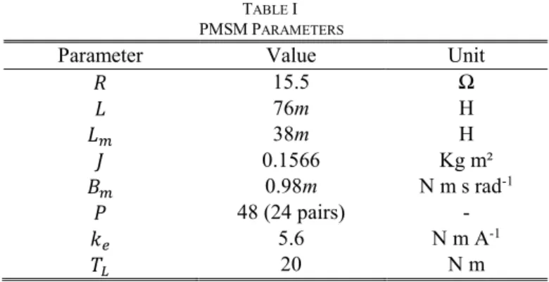
utilized motor parameters are presented in Table I.
TABLE I PMSMPARAMETERS
Parameter Value Unit
𝑅 15.5 Ω 𝐿 76m H 𝐿𝑚 38m H 𝐽 0.1566 Kg m² 𝐵𝑚 0.98m N m s rad-1 𝑃 48 (24 pairs) - 𝑘𝑒 5.6 N m A-1 𝑇𝐿 20 N m
*m stands for milli and m for meter.
III. PICONTROLLERS DESIGN
A block diagram for FOC using PI controllers is shown in Figure 1. The speed controller, PIω, generates the reference for 𝑖𝑞. The output of PI𝑖𝑞 is the 𝑞-axis voltage, 𝑣𝑞. These two controllers compose the cascaded control loop in a PI-based FOC. A third controller, PI𝑖𝑑, is used to track the reference for 𝑖𝑑, producing the direct axis voltage 𝑣𝑑. To achieve a MTPA
condition, the reference for 𝑖𝑑 is set to zero. The SVM block is
used to perform modulation, driving a three-phase bridge inverter, producing three-phase switched voltage inputs for the PMSM. Rotor electrical position, 𝜃𝑒, is provided to the SVM
block. Feedback for the current control loops is provided through Park’s transform.
Fig. 1. FOC using PI controllers. The area delimited by the dashed rectangle indicates the use of cascaded control.
The design of the tested PI controllers was performed with the aid of Internal Model Control (IMC) methodology, which consists in combining the inverse model of the plant, a filter and a reference model. By designing the IMC control structure, it is possible to obtain an equivalent conventional controller. For a stable and minimum-phase plant model, it is possible to design a controller such that the closed-loop transfer function is equal to the employed filter transfer function. Such design procedure is given as follows [11]:
Define a representative transfer function model for the plant, given by 𝐺𝑐(𝑠);
Specify the closed-loop bandwidth 𝜔𝑐;
Design a filter 𝑓(𝑠) = 1 (𝑠
𝜔𝑐+1)
𝑛, with 𝑛 equal to the plant order;
Make 𝑞(𝑠) = 𝑓(𝑠) 𝐺𝑐(𝑠),
Obtain the controller 𝑐(𝑠) = 𝑞(𝑠) 1−𝐺𝑐(𝑠)𝑞(𝑠);
Obtain an equivalent discretized controller for digital implementation.
If the plant is represented by a first order model, this procedure leads to a PI controller:
𝑐(𝑠) = 𝐾𝑝+
𝐾𝑖
𝑠 (5)
The transfer function models for 𝜔𝑚, 𝑖𝑞 and 𝑖𝑑, as functions
of 𝑖𝑞, 𝑣𝑞 and 𝑣𝑑, respectively, are given below, neglecting the
coupling between variables and nonlinearities given by the state space model in (1):
𝜔𝑚(𝑠) 𝑖𝑞(𝑠) = 1.5𝑘𝑒 𝑠𝐽 + 𝐵𝑚 (6) 𝑖𝑞(𝑠) 𝑣𝑞(𝑠) = 𝑖𝑑(𝑠) 𝑣𝑑(𝑠) = 1 𝑠𝐿𝑒+ 𝑅 (7)
With this methodology, the obtained controller transfer functions 𝑐𝜔(𝑠) and 𝑐𝑖(𝑠) for speed and current, respectively,
are: 𝑐𝜔(𝑠) = 𝜔𝑐𝜔 𝑠𝐽 + 𝐵𝑚 1.5𝑘𝑒𝑠 (8) 𝑐𝑖(𝑠) = 𝜔𝑐𝑖 𝑠𝐿𝑒+ 𝑅 𝑠 (9)
Using a switching frequency of 1 kHz, the current bandwidth 𝜔𝑐𝑖 was set to 628 rad/s, or 100 Hz. The speed loop
bandwidth 𝜔𝑐𝜔 was set to 62.8 rad/s, or 10 Hz, to ensure a
reasonable decoupling between the controllers.
Regarding the speed controller, using the controller zero 𝜔𝑧= 𝐵𝑚/𝐽 to cancel the speed pole leads to a very small
integrative gain, 𝐾𝑖= 𝜔𝑐𝜔𝐵𝑚/(1.5𝑘𝑒). Without any load, this
condition does not cause convergence problems. However, when a load torque is applied to motor axis, the closed-loop settling time becomes very high. Due to this, the frequency of the speed controllers zero, 𝜔𝑧, was set at higher frequencies
than the speed pole. Using higher values than 𝜔𝑧= 6000𝐵𝑚/𝐽 resulted in highly oscillatory responses,
while values smaller than 𝜔𝑧= 300𝐵𝑚/𝐽 resulted in slow
convergence for motor speed.
Two different tunings for the speed PI and the current loop PI tuning are shown in Table II. We refer to PI-1 as the controllers set composed by PI-1ω and PIi (the same tuning is
used for 𝑖𝑞 and 𝑖𝑑) and PI-2 as the controllers set composed by
PI-2ω and PIi (the same current loop, PIi, was used with both PI-1ω and PI-2ω).
JOURNAL OF APPLIED INSTRUMENTATION AND CONTROL 4
TABLE II
SPEED AND CURRENT LOOP PI CONTROLLERS’ PARAMETERS
𝜔𝑧 𝐾𝑝 𝐾𝑖 𝜔𝑐
PI-1ω 6000𝐵𝑚/𝐽 1.171 43.973 62.8 rad/s (10 Hz)
PI-2ω 300𝐵𝑚/𝐽 1.171 2.198 62.8 rad/s (10 Hz)
PIi 𝑅/𝐿𝑒 23.88 9734 628 rad/s (100 Hz)
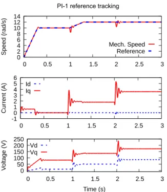
A test of reference tracking and step load rejection was performed for each PI controller set. Figure 2 shows the results for PI-1 while Figure 3 shows the results for PI-2. As it can be observed, in both cases the controllers were able to regulate 𝑖𝑑 current to zero. PI-1 presented a much faster speed
response, but with greater control peaks and oscillations in the application of loads at 1 s (20 Nm) and 2 s (30 Nm).
Fig. 2. PI-1 reference tracking with load torque steps.
IV. MPCCONTROLLER
MPC is a family of digital controllers which operate based on the optimization of the future behavior of the control loop over a given horizon of 𝑁 samples by using a prediction model [12]. By defining a cost function, an optimization method is used in MPC to find the sequence of 𝑀 variations in the control actions which minimizes the referred cost function. MPC has the advantages of handling multivariable coupled plants and solving optimization problems with constraints [3].
With a multivariable approach, FOC using MPC is implemented as shown in Figure 4. The controller block receives feedback of 𝜔𝑚, 𝑖𝑞 and 𝑖𝑑. Then, using the
prediction model and the references for 𝜔𝑚 and 𝑖𝑑, control
actions 𝑣𝑑 and 𝑣𝑞 are generated through an optimization
method. Depending on the employed MPC approach, integrators might be included in the MPC block.
Fig. 3. PI-2 reference tracking with load torque steps.
Fig. 4. FOC using multivariable MPC.
In the following, an overview of the steps to implement the state space MPC strategy is given. For more detailed information, the reader is referred to [3, 13].
In this work, the employed prediction model was obtained from a discrete state space model, obtained by discretization of the continuous state space model in (1). The discretized state space model for the PMSM is given by:
𝑥𝐷(𝑘 + 1) = 𝐴𝐷𝑥𝐷(𝑘) + 𝐵𝐷𝑢𝐷(𝑘) (10)
𝑦𝐷(𝑘) = 𝐶𝐷𝑥𝐷(𝑘) (11)
The variables in such model are defined as: 𝑥𝐷(𝑘) =
[𝑖𝑑(𝑘) 𝑖𝑞(𝑘) 𝜔𝑚(𝑘)]𝑇, 𝑦𝐷(𝑘) = [𝑖𝑑(𝑘) 𝜔𝑚(𝑘)]𝑇,
𝑢𝐷(𝑘) = [𝑣𝑑(𝑘) 𝑣𝑞(𝑘)]𝑇, 𝐴𝐷= 𝐼 + 𝑇𝑠𝐴𝑐 and 𝐵𝐷 = 𝑇𝑠𝐵𝑐,
where 𝑇𝑠= 1 𝑚s and 𝐴𝑐 and 𝐵𝑐 are the continuous state space
matrices given in (1).
For including an integrative characteristic to the control loop, the prediction model is augmented to:
JOURNAL OF APPLIED INSTRUMENTATION AND CONTROL 5 𝑦(𝑘) = 𝐶𝑥(𝑘) (13) with 𝐴 = [𝐶𝐴𝐷 0 𝐷𝐴𝐷 𝐼] 𝐵 = [ 𝐵𝐷 𝐶𝐷𝐵𝐷] 𝐶 = [02×3 𝐼2×2] (14)
using 𝑦(𝑘) = [𝑖𝑑(𝑘) 𝜔𝑚(𝑘)]𝑇 as output. The state vector is
𝑥(𝑘) = [𝛥𝑖𝑑(𝑘) 𝛥𝑖𝑞(𝑘) 𝛥𝜔𝑚(𝑘) 𝑖𝑑(𝑘) 𝜔𝑚(𝑘)]𝑇 and
the input vector is 𝛥𝑢(𝑘) = [𝛥𝑣𝑑(𝑘) 𝛥𝑣𝑞(𝑘)]𝑇. The
operator 𝛥 denotes the variation of a given variable between two sampling periods: 𝛥𝑓(𝑘) = 𝑓(𝑘) − 𝑓(𝑘 − 1) for a generic variable 𝑓(𝑘).
Weighting matrices are defined for the predicted inputs and outputs as 𝛬 and Γ, respectively, by:
𝛬 = [𝜆𝜔0𝑚 𝜆0
𝑖𝑑
] Γ = [𝛾0𝑣𝑑 𝛾0
𝑣𝑞
] (15)
where 𝜆𝜔𝑚 and 𝜆𝑖𝑑 are the speed and current predicted errors weights, respectively, and 𝛾𝑣𝑑and 𝛾𝑣𝑞 are the input efforts cost weights for 𝑣𝑑 and 𝑣𝑞, respectively. Using such weighting
matrices, a cost function which consists in a compromise between control efforts and reference tracking can be defined as: 𝐽𝑐𝑜𝑠𝑡(𝑘) = ∑[𝑦𝑒𝑟𝑟𝑜𝑟(𝑘 + 𝑗|𝑘)]𝑇 𝑁 𝑗=1 𝛬[𝑦𝑒𝑟𝑟𝑜𝑟(𝑘 + 𝑗|𝑘)] + ∑[𝛥𝑢(𝑘 + 𝑗 − 1|𝑘)]𝑇 𝑀 𝑗=1 𝛤[𝛥𝑢(𝑘 + 𝑗 − 1|𝑘)] (16)
in which 𝑓(𝑘 + 𝑗|𝑘) stands for the prediction for variable 𝑓 at time 𝑘 + 𝑗, considering the available information at time 𝑘, and 𝑦𝑒𝑟𝑟𝑜𝑟(𝑘 + 𝑗|𝑘) = 𝑦(𝑘 + 𝑗|𝑘) − 𝑦𝑟𝑒𝑓(𝑘 + 𝑗), where
𝑦𝑟𝑒𝑓(𝑘) is the output reference. In this work, both 𝑦(𝑘 + 𝑗|𝑘)
and 𝑦𝑟𝑒𝑓(𝑘 + 𝑗) are 2-dimentional vectors, as there are two
outputs in the considered PMSM control system.
It is possible to rewrite the cost function in a vector form, by augmenting the weight matrices to 𝛬̅ and Γ̅ to fit the prediction (𝑁) and control (𝑀) horizons, respectively, as [13]:
𝛬̅ = [ 𝛬 02×2 ⋯ 02×2 02×2 𝛬 ⋯ 02×2 ⋮ ⋮ ⋱ ⋮ 02×20 02×2 ⋯ 𝛬 ] (17) Γ̅ = [ Γ 02×2 ⋯ 02×2 02×2 Γ ⋯ 02×2 ⋮ ⋮ ⋱ ⋮ 02×2 02×2 ⋯ Γ ] (18)
Also, by using the prediction model for 𝑁 steps prediction in a vector form, in the unconstrained MPC case, it is possible to obtain an expression for the optimal control increment sequence: 𝛥𝑈∗= (𝐻𝑇𝛬̅𝐻 + Γ̅ )−1𝐻𝑇𝛬̅[𝑌 𝑟𝑒𝑓− 𝛷𝑥(𝑘)] (19) where 𝐻 = [ 𝐶𝐵 0 … 0 𝐶𝐴𝐵 𝐶𝐵 … 0 ⋮ 𝐶𝐴𝑁−1𝐵 ⋮ 𝐶𝐴𝑁−2𝐵 . … 𝐶𝐴𝑁−𝑀2⋮ 𝐵 ] (20) and 𝛷 = [𝐶𝐴 𝐶𝐴2 … 𝐶𝐴𝑁]𝑇 (21)
with the 𝑁 future reference samples contained in 𝑌𝑟𝑒𝑓.
Finally, at each sampling instant, 𝛥𝑈∗ is calculated and the
first increment of such sequence is applied to the control actions, using the receding horizon strategy [3]. Such strategy is used to allow the controller to update the control actions at each sampling instant, for handling disturbances and errors between the prediction model and the real plant.
The controller parameters were set with 𝑁 = 8, 𝑀 = 2, 𝜆𝜔𝑚 = 0.1, 𝜆𝑖𝑑 = 1, 𝛾𝑣𝑑= 0.5/200² and 𝛾𝑣𝑞= 0.5/200². The horizons were set in a manner that the resulting computational time was at most 0.1 ms (10% of the sampling period) in computer simulation. As the use of a larger control horizon 𝑀 did not generate significant improvements, the prediction horizon was increased to 𝑁 = 8, with 𝑀 = 2, to achieve the designed computational load. The embedded application can perform a better computational time than the obtained in the simulation [5], which implies a feasible horizon choice. The weighting matrix 𝛬 was set in a manner that speed and current objectives had similar importance, considering that numeric value of the nominal speed is higher than the expected current error values. This was a guided empirical tuning. However, a normalization procedure could also have been done to achieve the same result. The control action weights were set equally, so both speed and current objectives could be fairly considered. A normalizing weight of 200² was firstly set, considering a nominal voltage of 200 V, and a coefficient of 0.5 was applied to achieve fast responses without generating higher voltage peaks than the utilized PI controllers.
A test was performed to evaluate the constant reference tracking and load rejection of MPC with SVM. Figure 5 shows the resulting speed, currents and voltages for the MPC controller. Comparing to PI-1, the obtained reference tracking dynamics was similar. The speed oscillations when load torque steps were applied were, however, smaller for MPC, with also lower current and voltage peaks.
V. FREQUENCY RESPONSE RESULTS
In this section, the results involving frequency responses are presented. Control saturation was handled with an anti-windup strategy for the PI controllers. The utilized MPC methodology is unconstrained and based on control increments, without integrating errors. Thus, simple saturators were used for MPC. In all simulations, a limit of ±200 V was applied to both input voltages 𝑣𝑑 and 𝑣𝑞.
JOURNAL OF APPLIED INSTRUMENTATION AND CONTROL 6
Fig. 5. MPC reference tracking with load torque steps.
A. Dynamic stiffness
Dynamic stiffness is defined as the amplitude of a disturbance, in a given frequency, which produces an output response with unitary amplitude in a dynamic system [7]. In the case of an electric motor, it is interesting to observe the effects of a load torque, as a disturbance, and the resulting closed-loop speed oscillation, as the response.
To perform the dynamic stiffness measurement, the controllers PI-1, PI-2 and MPC were tested by varying the frequency of a sinusoidal load torque of amplitude 5 Nm. Such disturbance was applied over an operational speed point of 𝜔̂𝑚= 10 rad/s and 20 Nm of constant load torque. Figure 6
shows the result of one of the tests performed with PI-I, with a 10 Hz torque disturbance.
The speed output for the same test using MPC is shown in Figure 7. MPC rejected the disturbance with more attenuation than PI-I at 10 Hz, due to its higher speed bandwidth. The objective of such comparison is to show that a cascade free control loop is able to better attenuate low frequency AC disturbances using the same switching frequency than the PI-based cascaded control strategy, which was designed to achieve the highest closed-loop bandwidth while respecting a bandwidth limit due to the switching frequency for the current loop and a decoupling limit for the speed loop. The dynamic stiffness is then calculated as the amplitude of the disturbance divided by the amplitude of the speed response oscillation. Collecting simulation data from 2 Hz up to 200 Hz of disturbance, a dynamic stiffness plot was created, considering the three tested controllers. The resulting plot is shown on Figure 8. It is possible to observe that, at low frequencies, in which the controller is the main responsible for the stiffness, MPC presented the best result, while 1 over-performed PI-2. At medium frequencies (from 30 Hz to 100 Hz), the PI controllers presented a slightly greater stiffness than MPC and, as the frequency increases, all controllers result in the same
stiffness. This occurs because at high frequencies the controllers do not have enough bandwidth to reject the disturbance, but the motor inertia attenuates the oscillations, which has the same effect for the three control loops.
Fig. 6. AC torque sweep procedure with PI-1 at 10 Hz.
JOURNAL OF APPLIED INSTRUMENTATION AND CONTROL 7
Fig. 8. Dynamic stiffness using MPC and both PIs;
B. AC reference sweep
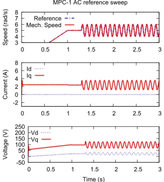
The frequency analysis was also performed using sinusoidal speed reference signals over the same operational point as in the stiffness test. In this analysis, the MPC controller was tested in two conditions. The first, MPC-1 users a vector 𝑌𝑟𝑒𝑓
with all elements equal to the instant reference. In the second, MPC-2, the future reference within the prediction was informed to the controller. Figure 9 shows an AC reference sweep for MPC-1 at 10Hz, over an operating speed 𝜔̂𝑚= 5
rad/s, while Figure 10 presents the same procedure for PI-1.
Fig. 9. AC reference sweep procedure with MPC-1 at 15 Hz.
It can be observed that 𝑖𝑑 was regulated to zero in both
approaches. The obtained speed with MPC-1 presented a practically unitary gain, while with PI-1 the speed was amplified in relation to the reference. Using a higher operating point than 𝜔̂𝑚= 5 rad/s for the AC reference sweep caused
instability problems between 10 Hz and 25 Hz with PI-1 due to control saturation.
The resulting Bode diagram for the four tested controllers, PI-1, PI-2, MPC-1 and MPC-2, is presented in Figures 11 and 12. Firstly, it can be observed that the MPC controllers presented a larger bandwidth than the PIs. Secondly, PI-1
started with a higher gain than PI-2, presenting a maximum value of approximately 7.88 dB. For frequencies higher than 30 Hz, PI-1 and PI-2 presented very similar responses. This means that at such frequencies the proportional gain, that is the same in both PI-1 and PI-2, is the main actuating component.
Fig. 10. AC reference sweep procedure with PI-I at 15 Hz.
Fig. 11. Gain curves using MPC-1, MPC-2, PI-1 and PI-2.
JOURNAL OF APPLIED INSTRUMENTATION AND CONTROL 8
Observing the phase plot, it is possible to conclude that the reference anticipation resulted in a significantly phase delay reduction for MPC-2, when compared to MPC-1. 1 and PI-2 presented similar characteristics, starting at nearly 0, moving towards −180°. It is interesting to notice that MPC-2 had a positive slope in phase starting from 50 Hz. However, at higher frequencies, the attenuation of MPC-2 was almost total.
VI. CONCLUSION
In this work, two control approaches were tested for a PMSM SVM-FOC drive with a relatively low switching frequency of 1 kHz. A low frequency modulation enhances the results obtained with MPC, since the PI cascade controllers need to be designed with decoupling frequency margins. The results with the PI controllers, however, are satisfactory, since they are very simple controllers with a smaller computational cost than MPC. The MPC controller, by its turn, presented a more significant stiffness curve for low frequency disturbances and larger bandwidth than the PIs. With a low switching frequency the commutation losses and the cost of inverter compounds are lower, and the MPC can be applied to better explore this condition.
With the present study, the most significant performance improvement by using MPC in relation to PI control is the better disturbance attenuation and trajectory tracking for low frequencies. This is important in a range of applications, since PMSMs are widely used in home appliances, such as washing machines, in which the motor is subject to low frequency mechanical disturbances.
ACKNOWLEDGEMENT
The authors acknowledge Santa Catarina State University for the financial support to G. H. Negri, by means of the Graduate Monitoring Scholarship Program (PROMOP), and Tutorial Learning Program (PET) from the Ministry of Education of Brazil.
REFERENCES
[1] P. Pillay and R. Krishnan, “Modeling, Simulation, and Analysis of Permanent-Magnet Motor Drives, Part I: The Permanent-Magnet Synchronous Motor Drive”, IEEE Transactions on Industry
Applications, vol. 25, no. 2, pp. 265-273,March, 1989.
[2] P. Pillay and R. Krishnan, “Modeling of permanent magnet motor drives”, IEEE Transactions on Industry Applications, vol. 35, no. 4, pp. 537-541 ,November, 1988.
[3] J. M. Maciejowski. Predictive Control with Constraints. Prentice-Hall, Harlow, 2002.
[4] M. Preindl and S. Bolognani, “Comparison of direct and pwm model predictive control for power electronic and drive systems”. In 2013
Twenty-Eighth Annual IEEE Applied Power Electronics Conference and Exposition (APEC), pages 2526 – 2533, Long Beach, CA, USA,
2013.
[5] M. Preindl and S. Bolognani, “Optimal state reference computation with constrained mtpa criterion for pm motor drives”, IEEE Transactions on Power Electronics, vol. 30, no. 8, pp. 4524-4535, 2015. [6] A. G. Bartsch, G.H. Negri, C. R. Scalabrin, M. S. M. Cavalca, A. Nied and J. de Oliveira, “Predictive control approach for permanent magnet synchronous motor drive”, Eletrônica de Potência, vol. 20, no. 4, pp. 395–403, 2015.
[7] R. D. Lorenz and P. B. Schmidt, “Synchronized motion control for process automation”. In Conference Record of the 1989 IEEE Industry
Applications Society Annual Meeting, San Diego, 1989.
[8] E. Fuentes, D. Kalise, J. R. and R. M. Kennel, “Cascade-free predictive speed control for electrical drives”. IEEE Transactions on Industrial
Electronics, vol. 61, no. 5, pp. 2176–2184, May 2014.
[9] M. Preindl and S. Bolognani, “Model predictive direct speed control with finite control set of pmsm drive systems”. IEEE Transactions on
Power Electronics, vol. 28, no. 2, pp. 1007–1015, February 2013.
[10] D. W. Novotny and T. A. Lipo. Vector Control and Dynamics of AC
drives. Oxford Science Publications, 1996.
[11] D. E. Rivera. Internal model control: A comprehensive view. Arizona State University, 1999.
[12] S. J. Qin and T. A. Badgwell, “A survey of industrial model predictive control technology”, Control Engineering Practice, vol. 11, pp. 733– 764, 2003.
[13] G. H. Negri, A. G. Bartsch, M. S. M. Cavalca, J. de Oliveira, A. Nied, and A. S. Silveira, “Model-based predictive direct speed control applied to a permanent magnet synchronous motor with trapezoidal back-emf”. In 2014 11th IEEE/IAS International Conference on Industry
Applications (INDUSCON), Juiz de Fora, BR, 2014.
Received: 30 May 2017; Accepted: 26 January 2018; Published: 06 April 2018
© 2018 by the authors. Submitted for possible open access publication under the terms and conditions of the Creative
Commons Attribution (CC-BY) license