University of Aveiro 2015
Department of Materials and Ceramic Engineering
Luís Filipe
Santos Barbosa
Active protective sealing for PEO treated
magnesium alloys
Dissertation submitted to the University of Aveiro to fulfill the requirements for obtaining a Master's degree in materials engineering, held under the scientific guidance of Dr. Maria Serdechnova, post – doctoral researcher at Helmholtz-Zentrum Geesthacht and Professor Mikhail Zheludkevich invited associate professor at Department of Ceramic and Materials Engineering at the University of Aveiro and head of Corrosion and Surface Technology Department of Magnesium Innovation Center of Helmholtz-Zentrum Geesthacht.
ii
The Jury Doctor João André da Costa Tedim
Assistant researcher in Department of Materials and Ceramic Engineering at the University of Aveiro.
Professor Victor Fernando Santos Neto
Invited assistant professor at Department of Mechanical Engineering - University of Aveiro.
Professor Mikhail Larionovich Zheludkevich
Invited associated professor at Department of Materials and Ceramic Engineering - University of Aveiro.
Doctor Maria Vladimirovna Serdechnova
Post – doctoral researcher at Helmholtz-Zentrum Geesthacht (HZG).
iv
Acknowledgements I would like to express my deepest thank to my family and friends, especially to my parents for their support and patience in every circumstance.
To University of Aveiro and Helmholtz-Zentrum Geesthacht (HZG) all my gratitude for the amazing opportunity to work and learn in such a great research center, especially to Professor Mikhail Zheludkevich for His trust and help.
To my supervisor Dr. Maria Serdechnova a special thank you for all the patience, support and knowledge passed to me, also the relaxing and laughing moments were important, thank you very much.
A huge thanks to all my colleagues at HZG for the help and good moments spent together. In particular to Dr. Carsten, Engineer Volker, Xiaopeng, Damla and my office mates. I couldn´t forget two persons that dedicates a lot of their own time to help and thought me every time I needed, a tremendous thank you to Dr. Marta Mohedano and Mr. Ulrich Burmester.
vi
Resumo Neste trabalho pretende-se selar a porosidade de
revestimentos aplicados na liga de magnésio AM50 através de oxidação por plasma eletrolítico (PEO). Nanocontentores constituídos por Hidróxidos duplos lamelares (LDHs - Layered
Double Hydroxides) foram testados como selantes.
Procedeu-se à síntese de LDH’s para intercalação de inibidores de corrosão. Os LDH foram sintetizados na superfície de uma liga de magnésio AM50, através de dois métodos diferentes, aqui denominados por “in situ 1 e “in
situ 2”. No método in situ 1 os catiões de magnésio (Mg2+) necessários à formação da estrutura dos LDH provêm exclusivamente da liga metálica, enquanto que no método in
situ 2 é realizada uma síntese pelo método de
co-precipitação, em que a nucleação para o crescimento dos LDHs pode ser feita diretamente na superficie da liga de magnésio ou sobre um revestimento intermédio. Os nanocontentores foram intercalados com o inibidor de corrosão 2 – Mercaptobenzothiazole. Por forma a crescer um revestimento cerâmico na superfície da liga AM50 utilizou-se o método de PEO. O método in situ 2 foi então utilizado para crescer LDH na superfície tratada com PEO de modo a selar a porosidade do filme e atribuir-lhe propriedades de auto-reparação “inteligente”.
A caracterização microestrutural e química dos LDH e dos filmes cerâmicos foi efectuada por microscopia eletrónica de varrimento (SEM – Scanning Electron Microscopy) e por difração de raios X (XRD – X-Ray Diffraction).
A avaliação do desempenho anticorrosivo dos nano-contentores aplicados diretamente na superfície metálica e na liga pré-tratada com PEO foi efectuada através de espectroscopia de impedância eletroquímica (EIS – Electrochemical Impedance Spectroscopy).
vii
Palavras - chave Nanocontentores “inteligentes, oxidação por plasma eletrolítico, inibidores, AM50, proteção anticorrosiva
viii
Abstract This work pretends to test active sealants for the porosity of plasma electrolytic oxidation (PEO) coatings applied in AM50 magnesium alloy. Layered double hydroxides (LDH) were chosen as active nanocontainers and were synthesized by two different methods, so called “in situ 1” and “in situ 2” on the surface of AM50 alloy. For the in situ 1 method, the alloy substrate is used as source of cations (Mg2+) to form the LDH structure, while in situ 2 is based in co-precipitation method, with the surface acting as a nucleation point for the LDH growth. The LDH nanocontainers were intercalated with 2– Mercaptobenzothiazole. PEO was used to grow a ceramic layer on AM50 surface. In situ 2 synthesis was used to grow LDH on the surface of the ceramic PEO layer to seal the porosity of the PEO coating and add “smart” self-healing ability to this layer.
The LDH and PEO coatings were analyzed using scanning electron microscopy (SEM) and X-ray diffraction (XRD). Electrochemical impedance spectroscopy (EIS) was performed in both LDH on the surface of bare AM50 and LDH on the PEO surface in order to evaluate their corrosion behavior.
Keywords “Smart” nanocontainers, plasma electrolytic oxidation, inhibitors, AM50, corrosion protection
x
Abstrakt In dieser Studie wurden sogenannte layered double
hydroxides (LDH) mittels zweier unterschiedliche Methoden
(in Folge "in situ 1" und "in situ 2" genannt), auf der Oberfläche der Magnesiumlegierung - AM50 synthetisiert. LDH's dienen typischerweise als Nanocontainer für Korrosionsinhibitoren.
Innerhalb der ersten Methode "in situ 1" wurde die Substratlegierung selbst als (Mg2+) - Kationenquelle genutzt, um die Strukturbildung und das Wachstum der LDH 's zu gewährleisten. Die Methode "in situ 2" hingegen sah vor, die AM50 Oberfläche selbst, lediglich als Keimbildungsort für das LDH-Wachstum zu nutzen.
Im nächsten Schritt wurden die LDH Nanocontainer mit dem Inhibitorsystem 2–Mercaptobenzothiazole beladen, mit dem Ziel, sie in einer Keramikschicht auf der AM50 Oberfläche einzulagern. Die Schicht selbst wurde mittels PEO hergestellt. Die "in situ 2" Synthesemethode wurde genutzt, um LDH's auf der Oberfläche einer PEO-Keramikschicht wachsen zu lassen. Ziel war das absenken der Porösität (versiegeln) der PEO-Schicht. Komplementär wurde der Schicht so ebenfalls (durch die beladenen Nanocontainer) die Fähigkeit zur aktiven "intelligenten" Selbstheilung vermittelt.
Die LDH/PEO Schichtsysteme wurden systematisch mit einem Rasterelektronenmikroskop (REM) und mittels Röntgendiffraktometrie (XRD) untersucht. Um den Einfluss der LDH's auf das Korrosionsverhalten der AM50- bzw. Der PEO-Oberfläche zu beurteilen, wurde elektrochemische Impedanzspektroskopie durchgeführt. Der experimentellen Ergebnisse wurden zur abschließenden Bewertung des Ansatzes verwendet.
Schlüsselwörter “intelligente” Nanocontainer, plasma electrolytic oxidation, Inhibitoren , AM50, Korrosionsschutz
xii Content
List of abbreviations ... xiv
Figure content ... xvi
Table content ... xviii
Motivation ... xx
1. State of the art ... 1
1.1. Corrosion processes ... 1
1.2. Magnesium and magnesium alloys ... 2
1.3. Corrosion of Magnesium and Magnesium Alloys ... 3
1.4. Protection of Magnesium ... 4
1.4.1. Plasma electrolytic oxidation ... 5
1.5. Corrosion Inhibitors ... 9
1.6. Nanocontainers ... 11
2. Experimental conditions and procedure ... 13
2.1. Materials ... 13
2.1.1. Alloy ... 13
2.1.2. Reagents ... 13
2.2. Preparation of specimens ... 13
2.3. Layered double hydroxide synthesis ... 14
2.3.1. LDH grow by In situ 1 ... 14
2.3.2. LDH grow by In situ 2 ... 16
2.4. Plasma electrolytic oxidation ... 17
2.5. Inhibitors intercalation ... 19
2.6. LDH synthesis on PEO surface ... 19
2.7. Thermal treatment ... 19
2.8. Techniques ... 19
3. Results ... 21
3.1. SEM ... 21
3.1.1. AM50 magnesium alloy ... 21
3.1.3. PEO treated on AM50 magnesium ... 24
3.1.4. LDH treatment on PEO covered AM50 magnesium alloy ... 24
3.2. XRD ... 26
3.2.1. AM50 magnesium alloy ... 26
xiii 3.4. Polarization curves ... 41 4. Discussion ... 42 4.1. Mechanism of LDH protection ... 42 5. Conclusion ... 44 6. References ... 45
xiv List of abbreviations
LDH - Layered double hydroxides; PEO – Plasma electrolytic oxidation;
EIS - Electrochemical impedance spectroscopy;
SEM - Scanning electron microscopy; XRD – X – Ray diffraction;
MBT – 2-Mercaptobenzothiazole; AC – Alternating current;
xvi Figure content
Figure 1 - Corrosion process on the surface of metal. ... 1
Figure 2 - Scheme of PEO treatment cell. ... 5
Figure 3 - a) Scheme of a metal substrate coated with PEO. b) Cross section SEM image of AZ91 magnesium alloy coated with PEO - figure reproduced whit authorization of Elsevier Limited. ... 6
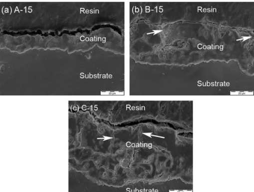
Figure 4 - SEM micrography of cross section of AM50 alloy after PEO treatment under different current density: a) 15 mA/cm2; b) 75 mA/cm2; c) 150 mA/cm2. Arrows show the pore channels18 - figures reproduced whit authorization of Elsevier Limited. ... 7
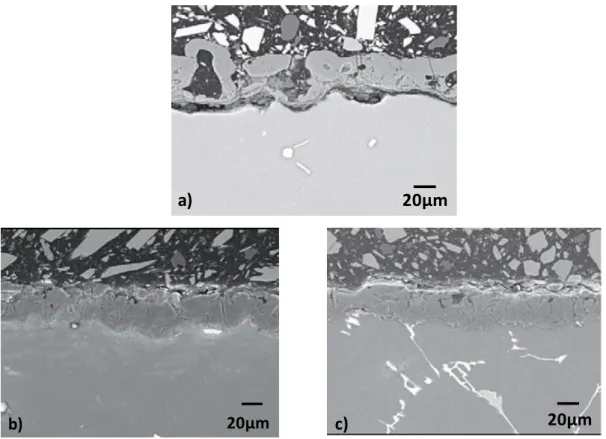
Figure 5 - Effect of the current in the final PEO properties. a) unipolar; b) bipolar and c) hybrid19 - figures reproduced whit authorization of Elsevier Limited. ... 8
Figure 6 - Nyquist plot of non-sealed PEO compared with sealed PEO with three different post-treatments21 - figure reproduced whit authorization of Elsevier Limited. ... 9
Figure 7 - Values of the total resistance for sealed and unsealed PEO after 3 days of immersion in 0.35 wt% NaCl solution23 - figure reproduced whit authorization of Elsevier Limited. ... 10
Figure 8- Molecular structure of 2–Mercaptobenzothiazole. ... 11
Figure 9 - Scheme of the inhibitor intercalation into LDH and the releasing process on the metal substrate surface. ... 12
Figure 10 - Representation of the standard specimen used. ... 14
Figure 11 - Scheme of the experimental procedure for activation step of in situ 1 synthesis. 15 Figure 12- Scheme of the in situ 2 synthesis method (left) and representation of the sample holder (right). ... 17
Figure 13 - Voltage waveform used in the PEO treatment. Ͳ indicates the period of the wave. ... 18
Figure 14 - The graphs show the evolution of the voltage and the current with the time of synthesis. ... 18
Figure 15- SEM image of AM50 magnesium alloy surface. ... 21
Figure 16 - EDS mapping results for AM50 magnesium alloy. ... 22
Figure 17 - SEM images of LDH synthesized by in situ 1 and in situ 2. ... 23
Figure 18 - Plan view SEM images of PEO coated AM50 magnesium alloy. ... 24
Figure 19 - cross section SEM images of PEO coated AM50 magnesium alloy. ... 24
Figure 20 - SEM images of PEO coated magnesium alloy post-treated with in situ 2 LDH. ... 25
Figure 21 - SEM images of PEO coated magnesium alloy surface submitted to thermal treatment. ... 25
Figure 22 - XRD pattern of AM50 magnesium alloy and Mg-Al LDH slurry. ... 26
Figure 23 - XRD pattern of in situ 1 LDH – NO3 and in situ 1 LDH - MBT on the surface of the magnesium alloy. ... 27
Figure 24 - Schematic representation of a proposed organization of the anions inside the LDH gallery. ... 28
Figure 25 - XRD pattern of in situ 2 LDH – NO3 and in situ 2 LDH – MBT on the surface of the magnesium alloy. ... 29
xvii
Figure 27 - XRD pattern of PEO treatment applied on AM50 alloy. ... 30 Figure 28 - XRD pattern of in situ 2 LDH – NO3 and in situ 2 LDH – MBT applied on PEO
coating. ... 31 Figure 29- Impedance spectra of both in situ 1 and in situ 2 LDH (without inhibitor) after 1, 10 and 24 hours of immersion in 0.5 wt% NaCl. ... 32 Figure 30- Impedance spectra of bare AM50, AM50 coated with LDH and AM50 coated with LDH intercalated with MBT after 1, 10 and 24 hours of immersion in 0.5 wt% NaCl. ... 34 Figure 31- Impedance spectra of PEO, PEO sealed with LDH and PEO sealed with LDH
intercalated with MBT after 1, 10 and 24 hours of immersion in 0.5 wt% NaCl. ... 35 Figure 32 - Example of the fitting obtained by Zview analysis with the respective equivalent circuit in the inset for LDH based coatings. ... 38 Figure 33 - Evolution of the coating resistance obtained by fitting for LDH based coatings. .. 38 Figure 34 - Example of the fitting obtained by Zview analysis with the respective equivalent circuit in the inset for PEO based coatings. ... 39 Figure 35 - Evolution of the coating resistance obtained by fitting for PEO based coatings. .. 40 Figure 36 - Polarization curves of bare alloy and LDH with nitrate and MBT. ... 41 Figure 37 - Scheme of the LDH distribution on the surface of magnesium AM50. ... 42 Figure 38 - Scheme of the LDH acting mechanism after a scratch occur in the surface. ... 42 Figure 39 - Scheme of the LDH distribution on the surface of magnesium AM50 pre-coated with PEO. ... 43
xviii Table content
Table 1 - Comparison of mechanical properties of different metals and metallic alloys. ... 2
Table 2 - Different conditions used for in situ 1 synthesis optimization. ... 16
Table 3 - Electrolyte composition ... 18
Table 4 - Quantification of the elements resulting from EDS spectrum analyses... 22
Table 5 - Reflections data for LDH - NO3 and LDH – MBT ... 27
Table 6- Impedance magnitude of both in situ 1 and in situ 2 LDH (without inhibitor) after 1, 10 and 24 hours of immersion in 0.5 wt% NaCl. ... 33
Table 7- Impedance magnitude of bare AM50, AM50 coated with LDH and AM50 coated with LDH intercalated with MBT after 1, 10 and 24 hours of immersion in 0.5 wt% NaCl. ... 34
Table 8 – Impedance magnitude of PEO, PEO sealed with LDH and PEO sealed with LDH intercalated with MBT after 1, 10 and 24 hours of immersion in 0.5 wt% NaCl. ... 36
xx Motivation
Magnesium has great potential to be used in structural engineering due to its suitable
mechanical properties associated with relatively low density (1.7g/cm3). However magnesium is known by its high reactivity that leads to fast corrosion, moreover, the corrosion products do not provide effective anti corrosion protection in certain working environments.
Avoid the contact between magnesium and the environment trough a physical barrier is an effective way to increase magnesium life time. Ceramic like coatings grown in the surface of magnesium produced via plasma electrolytic oxidation (PEO) represents an interesting possibility of protection. However the coatings produced by PEO methods are known for its characteristic porosity that weakens the physical barrier properties allowing electrolytes to penetrate into the coating.
This work intends to focus in the porosity problem and test active sealings based on layered double hydroxides (LDH) as possible solution. Hereupon the objectives of this thesis are:
Produce ceramic coatings on AM50 alloy using PEO.
Test LDH grown directly on the surface as possible nanocarrier for corrosion inhibitors.
1 1. State of the art
1.1. Corrosion processes
Corrosion of metals can be defined as the destructive attack of a metal through its interaction with environment1. It is a complex phenomenon which could occur into very different solutions2. Corrosion is an (electro)chemical reaction occurring usually by the direct contact of the metal with the aggressive corrosive environment (Figure 1).
Figure 1 - Corrosion process on the surface of metal.
The contact of the metal with aggressive environments – normally aqueous solutions containing NaCl – provides an electrochemical system with ionic conductivity near the metal surface allowing the occurrence of oxidation-reduction reactions at the respective electrodes. The most important reaction is the dissolution of metal; under these conditions can be represented by anodic reaction of metal oxidation:
M → Mn+ + ne- (1)
where M is the original metal, Mn+ is oxidized metal (can be in form oxide/hydroxide) and n are the number of electrons involved into the reaction (1)1.
The cathodic reaction during the corrosion processes can be presented as reduction of hydrogen (reaction 2), oxygen (reaction 3) or water (reaction 4):
2H+ + 2e- → H2 (2)
O2 + 2H2O + 4e- → 4OH- (3)
2H2O + 2e- → H2 + 2OH- (4)
The reaction (2) occurs mainly in acidic media with low O2 concentrations. The reaction (3) occurs preferably when high concentration of O2 is available. The reaction (4) occurs in neutral or basic medium in absence of O2. Increasing temperatures, concentration of O2 and concentration of aggressive species like Cl- accelerate the corrosion process1.
Mn+ M(s)
H2 e
-2
According to these reactions the cathodic area may be characterized by an increase of the pH near the metallic surface and into the solution around.
1.2. Magnesium and magnesium alloys
Magnesium is a relatively abundant element on earth and has been used for many years, especially during the two world wars when it was used in nuclear industry and to produce military airplane parts3. However in that time the fast corrosion of magnesium was not sufficiently considered and the short life time of magnesium parts lead to slump of consumption. Its utilization became restricted as additive into some other alloys (e.g. aluminum alloys)3.
Only in the nineties of the last century the interest to this metal was refreshed and its investigation was intensified specially in transports industry that continuously looks for lighter materials. Reducing the weight increases the energetic efficiency of vehicles.
Since magnesium is the lightest structural metal with low density4 and reasonable mechanical properties (Table 1) in comparison with typical metals used in transports industry – steel and aluminum alloys (AA) - it represents a possibility to achieve the weight reduction objectives. In construction applications magnesium is used in alloyed form with aluminum, zinc, manganese and some rare earths as the most used alloying elements. These alloys normally present reasonable specific strength, good castability and possibility of recycling.
On the other hand, low elastic modulus, limited cold workability, limited toughness, reduced high strength and creep resistance at elevated temperatures, high chemical reactivity and specially the corrosion behavior5 are the limitations of magnesium alloys applications3.
Table 1 - Comparison of mechanical properties of different metals and metallic alloys. Material Density (g/cm3) Tensile Strength (Mpa) Yield Strength (Mpa)
Magnesium 1.7 90.0 – 220.0 21.0 – 115.0
Mg Alloys ≈1.7 160.0 – 380.0 55.0 – 324.0
Mg Alloy AM50 - 230.0 125.0
3
1.3. Corrosion of Magnesium and Magnesium Alloys
Corrosion of Magnesium
As soon as magnesium becomes in a contact with atmospheric environment, the oxidation process starts and leads to the formation of magnesium oxide (reaction 5)5, which can be further converted into magnesium hydroxide in the presence of moisture (reaction 6)5 simultaneously the most common cathodic reaction occurring in the case of magnesium corrosion is water reduction (reaction 4)
2Mg + O2→ 2MgO (5)
MgO + H2O→ Mg(OH)2 (6)
The final product of the atmospheric corrosion of magnesium is the oxide/hydroxide layer on the metal surface (MgO or Mg(OH)2), which is relatively stable in the pH range between 8.5 to 11.56. Above pH 11.5, magnesium hydroxide becomes the most stable and predominant phase in the passivation process6.
Under acidic (pH<8.5) condition the oxide/hydroxide layer on the magnesium surface is not stable anymore and do not protect magnesium. The same happens when the material is in the contact with aggressive ions like chlorides, bromides, sulfates and chlorates leading to the further corrosion of magnesium6. Also, the layer is relatively soluble in water and does not provide effective protection especially if water is saturated with CO26 (due to the reaction 7).
Mg(OH)2 + CO2 → MgCO3 + H2O (7)
Corrosion of Magnesium alloys
It is necessary to discuss and understand the corrosion behavior of magnesium alloys due to the higher utilization of alloys for industrial aims3,7.
The alloying elements are crucial to the corrosion behavior of the magnesium alloys and they can be divided into three groups depending on their influence in the corrosion behavior:
The elements that do not change significantly the corrosion behavior: aluminum, manganese, sodium, silicon, tin, lead, zirconium, beryllium, cerium and yttrium6.
The elements that have a moderate influence in the corrosion: zinc, cadmium, calcium and silver6.
The most critical additives with serious acceleration of the corrosion processes: iron, nickel and copper6.
4
This difference in the influence on the corrosion behavior of magnesium alloys is related to the low solid state solubility of some elements and especially with the ability of the additives to act as a cathode (forming galvanic pairs).
The galvanic accelerated corrosion of magnesium is the most critical for the industrial aims due to the most negative electrochemical potential in the galvanic series8. This makes magnesium suitable for galvanic corrosion acceleration acting as an anode when in contact with other metals or when the alloy contains more noble phases or additives. This galvanic corrosion of magnesium is controlled principally by the conductivity of the media, difference of electrochemical potential with alloying materials, difference of area, distance between anode and cathode5.
1.4. Protection of Magnesium
The corrosion behavior of magnesium limits its application for industrial aims. For the improvement of the corrosion resistance of magnesium alloys, different methods have been proposed9:
Electrochemical Plating;
During the electrochemical plating the material is submerged into metal salt solutions, leading to the reduction of the metal from the solution9.
This method offers anti-corrosion behavior in mild conditions; however the high reactivity of magnesium and the variability of alloys make this method difficult to apply. Moreover, the metal salt solutions have a short lifetime and often are not environmental friendly.
Conversion Coatings;
Conversion coatings based on chromate, phosphate-permanganate, fluorozirconate, stagnate and lanthanide with the chromate being now the most efficient and frequently used9. These coatings are chemically bonded to the surface and offer good protection properties9.
However, in spite of the effective anti-corrosion properties, the toxicity of the chromate is relatively high and now their application is prohibited9.
Gas-Phase Deposition;
Gas-phase deposition has the ability to form relatively thick and environmental friendly coatings using a deposition method under high pressure and temperature conditions9.
5
The disadvantages of this method are related to the high cost, the stability of the substrates under high temperatures and the adhesion properties of the coating to the substrate. These coatings have poor information reported9.
Anodizing;
Anodizing is used to protect magnesium for many years10. A relatively thick ceramic coating forms on the surface and perform effective corrosion protection, excellent paint base and good cosmetic finish9. However the process of anodizing is also affected now by the prohibition of chromates which were usually used in the process9.
Due to the issues related with the utilization of chromates and the and the search for more effective coatings the term “anodizing” can combine two processes: the first one maintaining the basic principle of the conventional anodizing and a second one more advanced and recent process called plasma electrolytic oxidation (PEO) that have shown improved corrosion protection, wear resistance and thermal load capacity11.
PEO is the technique used in this work to produce protective coatings to magnesium, due to that a detailed introduction is needed.
1.4.1. Plasma electrolytic oxidation
In this Master work the focus will be on the samples which were undergone to the plasma electrolytic oxidation (PEO), which is a derivative of the traditional anodizing principle when the metal is submerged in an electrolyte and an electrical current is applied to form the coating12,13(Figure 2).
Figure 2 - Scheme of PEO treatment cell.
The first difference between traditional anodizing and PEO is the current application mode11,14. During classical anodizing, low direct current (DC) is used. In contrast during PEO preparation,
Metal Electrolyte Refrigerating Water flow Cathode Anode
6
high voltage alternating (AC), pulsed DC or bipolar current is used. The applied electrical discharge promotes the fast oxidation of the metal and as consequence a ceramic-like coating grows on the surface of the metal15.
The formed coating thickness typically varies from 50 to 100 µm and is composed of two or more layers (Figure 3): one dense and thin (few hundred nanometers11) layer near the metal surface and another one that is typically characterized for its porosity.
Figure 3 - a) Scheme of a metal substrate coated with PEO. b) Cross section SEM image of AZ91 magnesium alloy coated with PEO16 - figure reproduced whit authorization of Elsevier
Limited.
The principal variables that influence the PEO coating characteristics are:
Electrical parameters:
During the process high voltages above the dielectric breakdown of the coating - around 100V to 600 V – are used to create localized short-lived discharges on the coating. This leads to the increase of the current density and the localized temperature allowing the formation of high temperature phases17.
The discharges are the main responsible for the microstructure, thickness, roughness, porosity and hardness. The growth rate is normally around 1 - 10 µm/min and it is controlled by the discharges too. Changes in the applied voltage or current density during the PEO treatment directly affect density and intensity of the discharge events. The influence of the current density in the PEO coating can be observed in Figure 418 where it is clear that the coating thickness and the number and size of pores increase with the current density.
I II III
I - Metal Substrate II - Dense layer III - Porous layer
7
Figure 4 - SEM micrography of cross section of AM50 alloy after PEO treatment under different current density: a) 15 mA/cm2; b) 75 mA/cm2; c) 150 mA/cm2. Arrows show the
pore channels18 - figures reproduced whit authorization of Elsevier Limited.
The current mode is important to control the defects and thickness of the coating and has been reported19,11 that bipolar or hybrid current produce more dense coating with minimum defects then DC or unipolar (pulsed DC) modes – Figure 5 - this coatings have, in general, better corrosion resistance.
The differences in current mode are related with the shape of the signal that is applied:
In bipolar current mode cathodic and anodic current interspersed among themselves are applied.
In hybrid current mode null, cathodic and anodic current interspersed among themselves are applied.
In the case of unipolar mode, only anodic (positive DC pulse) or cathodic (negative DC pulse) interspersed with null current is applied.
8
Figure 5 - Effect of the current in the final PEO properties. a) unipolar; b) bipolar and c) hybrid19 - figures reproduced whit authorization of Elsevier Limited.
Electrolyte:
PEO treatment is known for the utilization of alkaline environmentally friendly electrolytes of silicate, phosphate or aluminate of fluoride in relative ely low concentration7.
Since the electrolyte is present during the oxidation reaction and the growth of the coating, it is normal that the composition of the formed coating has contributions from the electrolyte20 . Due to that the introduction of salts, complexes, colloids or fine solid particles represents a way to control the microstructure, roughness, porosity, hardness and wear properties10 of the coating since it is expected the formation of compounds resulting from interactions and reactions between the additives triggered by discharges.
The main advantages attributed to the PEO treated metals or alloys are the improved corrosion protection, increased wear resistance, high dielectric strength and heat resistance. However, there is a disadvantage related with the porosity of the coating that can make the coating sensitive to corrosion.
20µm
a)
20µm
9
To mitigate this behavior and taking into account that the surface morphology is indicated to add a polymeric, ceramic or even metallic coating on the top of oxide layer to form duplex coatings with more effective corrosion protection some solutions are purposed: immersion in corrosion inhibitor like phosphate, silicate or borate solutions7, impregnation with polymers7 and utilization of sol-gel techniques7.
One example of increased corrosion protection behavior can be found in Figure 6 21 where is possible to see a Nyquist plot comparing non-sealed PEO with PEO sealed with novel sol–gel coating, polytetrafluoroethylene and acrylate-ethylene copolymer with nanoparticles. It can be seen that all the sealed PEO’s show higher impedance then the non-sealed PEO.
Figure 6 - Nyquist plot of non-sealed PEO compared with sealed PEO with three different post-treatments21 - figure reproduced whit authorization of Elsevier Limited.
1.5. Corrosion Inhibitors
Corrosion inhibitors have been used to improve the anti -corrosion potential of metals for many years, and the most used inhibitor had been hexavalent chromium7. However the REACH directive 2000/53/EC prohibits the utilization of lead, mercury, cadmium and hexavalent chromium due to the hazardous of these substances in vehicles released to the market after 1 July of 200322. These prohibitions lead the intensification in the development of alternative corrosion inhibitors.
10
Inorganic inhibitors:
Some inorganic inhibitors have been proposed for Mg alloys. These inhibitors are cerium23, phosphates24 and silica-based23 inhibitors. During previous work with cerium based23 inhibitors and sol-gel23,25 based post treatments it was demonstrated the improvement in behavior of magnesium.
An example of corrosion improvement due to the use of cerium as a sealant for PEO applied in AM50 Mg alloy can be seen in the Figure 723 where the total resistance of the system resulting from impedance analyses is presented. It is clear an increasing of the resistance and the equivalent increase in corrosion protection behavior on the samples containing cerium.
Figure 7 - Values of the total resistance for sealed and unsealed PEO after 3 days of immersion in 0.35 wt% NaCl solution23 - figure reproduced whit authorization of Elsevier
Limited.
Organic inhibitors:
Although the mechanisms of protection with organic inhibitors are not well understood, the basic principle associated to them is the adsorption of organic molecules on the surface of metallic substrate and the formation of a barrier which prevent the contact between material and aggressive environment26.
Previous works with 2–Mercaptobenzothiazole (MBT) (Figure 8)27 have shown the effective inhibition on different metallic surfaces like iron28 and copper29,30 - containing alloys. It can be explained by the MBT absorbance on the metallic surface possibly due to a σ-bond formed between the pair of free electrons on the nitrogen and the metallic surface. This layer forms a barrier that stops the diffusion of oxygen and corrosive species to the surface and dissolution of the metal.
11
However there is no information reported about inhibition effect of MBT in the case of Mg alloys. However, this alloy contains an iron based intermetallic which acts as a local cathode during the magnesium corrosion31. Since the intercalation process of MBT in LDH is well known32 and it was shown that it works for iron28, 33, MBT will be tested as corrosion inhibitor for AM50 alloy.
Figure 8- Molecular structure of 2–Mercaptobenzothiazole.
1.6. Nanocontainers
For the effective protection of the material with an inhibitor, the easy access of the inhibitor to the surface should take place. The problems related with the ability to keep inhibitors into the pores must be solved using materials which are harmless for the environment and able to control the release of the inhibitors.
The solution could be the utilization of environmental friendly nanocontainers that are able to keep the inhibitors inside the structure and to prevent the contact between them and the coating or the environment. The interaction between the inhibitors and the coating can damage the coating and affect the barrier properties; also the proliferation of the inhibitors for the environment must be avoided due to toxicity. Moreover the inhibitor release should take place only when the container is triggered. Layered double hydroxides (LDH) are a type of nanocontainer that meets the requirements34.
Layered double hydroxides
Layered double hydroxides are hydrotalcite-like compounds35. LDH is known as a good anion-exchanger; these compounds present layered structure with positively charged layers of metallic (cations/hydroxides) intercalated with negatively charged layers of anions. Using the LDH capability to anionic exchange some inhibitors, like MBT or BTA, can be included into the structure in anionic form34 (Figure 9).
12
Figure 9 - Scheme of the inhibitor intercalation into LDH and the releasing process on the metal substrate surface.
When LDH is loaded with inhibitors and inserted into coating structure, it is placed near the metallic surface. When the substrate is in presence of an aggressive media containing chlorides and it starts to corrode the concentration of hydroxides resulting from the cathodic reaction normally increase. The concentration of anions near the metallic surface triggers the anions-exchange capability of LDH and inhibitors start being replaced by Cl- or possibly some OH-. These are the two main advantages of LDH:
Controlled release of the inhibitor only when corrosion starts.
Absorbance of aggressive chlorides.
Nitrate - LDH Inh -Inh -Inh -Inh -A n-A n-A n-A n-Intercalated LDH Inh -Inh -Inh -Inh- Cl -Metal Inh -Inh -Inh -Inhibitor release Cl -Cl -Cl -Cl -Cl -Inh -Inh -Inh -Cl
-13 2. Experimental conditions and procedure 2.1. Materials
2.1.1. Alloy
AM50 Magnesium alloy produced in MagIC – HZG via gravity cast ingot with the composition of approximately 4.74% Al, 0.383% Mn, 0.065% Zn, 0.063% Si, 0.002% Fe, 0.002% Cu and Mg balance was used.
2.1.2. Reagents
The reagents used in the preparation of the solutions used in PEO and LDH treatments and analyses were obtained from different suppliers:
Aluminum nitrate nonahydrate, Al(NO3)3∙9H2O, (≥98,5%); sodium nitrate, NaNO3(≥99,0%); Iron nitrate (III) nonahydrate, Fe(NO3)3∙9H2O (>99%) from MERCK (Germany).
2 –Mercaptobenzothiazole, C7H5NS2, (97%); 1H - Benzotriazole, C6H5N3, (99%); Nitric acid, HNO3, (36.5% - 38.0%) from Alfa Aesar (Germany).
Magnesium nitrate hexahydrate, Mg(NO3)2∙6H2O, (>98%); sodium hydroxide, NaOH, (≥99%) from CARL ROTH (Germany).
Sodium phosphate, Na3PO4, (Pure) from ACROS ORGANICS (EUA). Potassium hydroxide, KOH, (>85%) from Th. Geyer (Germany).
All chemicals were used without further purification. Deionized water was used as a solvent. 2.2. Preparation of specimens
Specimens with dimensions of 15x15x4 mm (Figure 10) were prepared via gravity cast ingot material. A threaded hole with 2.5 mm of diameter and 6 mm depth was made in one of the rectangular faces to be used as a connection point with the holders.
All faces of the specimens were ground using SiC paper up to 2500 grit to renew the surface before every surface treatment.
14
Figure 10 - Representation of the standard specimen used.
2.3. Layered double hydroxide synthesis
This master thesis is based on two different types of surface modification: layered double hydroxide (LDH) and plasma electrolytic oxidation (PEO). Their combination was also tested. Layered double hydroxides are normally produced via co-precipitation method where two metallic cations (with specific stoichiometric ratio) are added to a host solution under controlled pH, over the course of reaction, the two metallic cations starts to co-precipitate in solution forming LDH precursor species. After a thermal step the precursor recrystallize forming LDH.
However in this work the synthesis of the LDH will be performed by in situ growth methods in the surface of both - bare AM50 alloy and AM50 coated with PEO.
In situ growth means that the LDH will be synthesized using the surface of the samples as
substrate. Two methods of in situ synthesis were considered and they will be referred in this text as in situ 1, that uses the substrate as a source of cations and only one cation is added and
in situ 2 that follows the co-precipitation principle and the two metallic species are added.
2.3.1. LDH grow by In situ 1
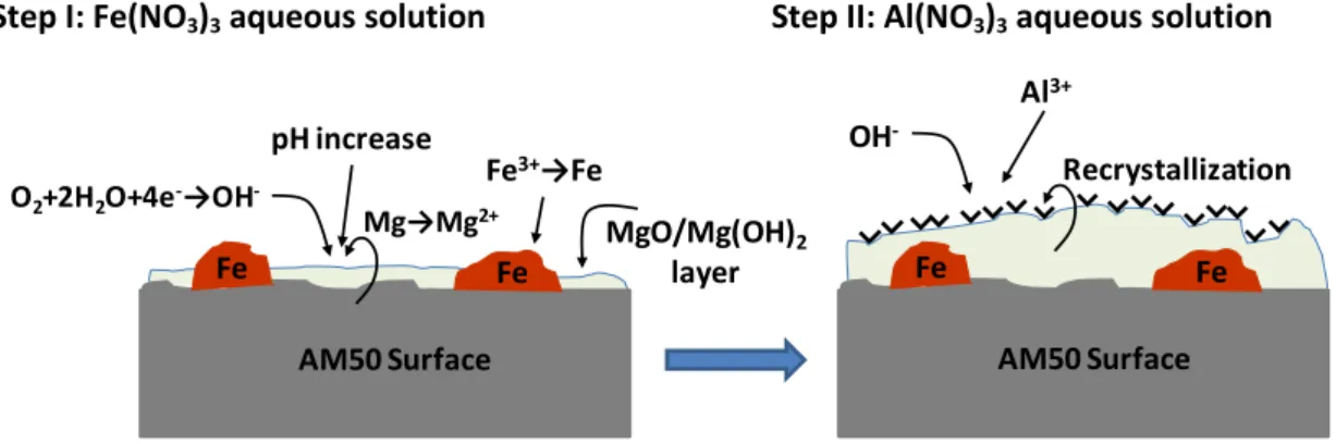
In the synthesis of LDH by so called “in situ 1” method, as mentioned, only one metallic specie were added - Al3+- and the substrate were the source of the second specie – Mg2+. This synthesis consists of two main steps that can be followed by the equations presented in Figure 11.
In the first step the surface of the magnesium alloy is activated by the presence of Fe(NO3)3 (Figure 11). Due to the presence of electrons iron starts to be reduced to his metallic form and precipitate in the surface of AM50 creating a galvanic couple. Due to the galvanic couple the magnesium from the substrate starts to dissolve and forms the oxide/hydroxide layer on the surface. At the same time OH- starts to form due to the cathodic reactions.
15
During the second step of the synthesis, the iron activated specimens are placed in 1M Al(NO3)3 solution. All the ions that are necessary to form the LDH structure are present and a typical structure of LDH with the general formula: [Mg2+1-xAl3+x (OH)2]x+(NO3-)x.mH2O starts to form via recrystallization processes in a solution reach of NO3- ions. Both steps of the synthesis were performed under constant temperature of 50°C.
Step I: Fe(NO3)3 aqueous solution Step II: Al(NO3)3 aqueous solution
Figure 11 - Scheme of the experimental procedure for activation step of in situ 1 synthesis.
To choose the optimal conditions, the specimens were immersed in solutions of iron (III) nitrate with different concentrations and different times of immersion. Different times of recrystallization were also used. Tested conditions are summarized in Table 2.
Must be noticed that AM50 alloy contains aluminum, because of that, a trial test were performed to verify if the substrate can be a source of both Al3+ and Mg2+. The used procedure is similar to the one described above and the specimens surface where also activated with different concentrations of iron nitrate and then replaced to a 1 M sodium nitrate solution as recrystallization solution. No LDH traces were found in those specimens.
Also a trial test of synthesizing LDH via in situ 1 where performed in PEO coated specimens, however no traces of LDH were found possibly due to the stability of the coating that avoid the substrate of being a source of cations to form the LDH structure.
AM50 Surface Fe Fe Fe3+→Fe Mg→Mg2+ O2+2H2O+4e-→OH -pH increase MgO/Mg(OH)2 layer AM50 Surface Fe Fe Recrystallization OH -Al3+
16
Table 2 - Different conditions used for in situ 1 synthesis optimization. Concentration of Fe(NO3)3
(g/l)
Immersion time in Fe(NO3)3 (Min) Recrystallization time (Min) 0 15 720 (12h) 15 1500 (25h) 0.001 10 10 30 60 60 60 15 720 (12h) 15 1500 (25h) 0.01 10 10 30 60 60 60 15 720 (12h) 15 1500 (25h) 0,05 10 10 30 60 60 60 15 720 (12h) 15 1500 (25h) 0,1 10 10 30 60 60 60 0,5 10 10 30 60 60 60 2.3.2. LDH grow by In situ 2
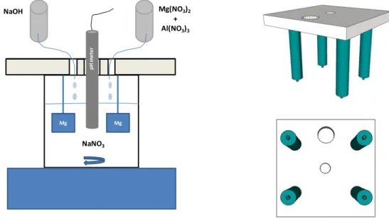
In the so called “in situ 2” method follow the experimental procedure described in literature36 for co-precipitation synthesis where a solution(50ml) of 0.025M aluminum nitrate and 0.05M magnesium nitrate is added drop by drop to an 0.2M (100ml) sodium nitrate solution under continuous stirring, the control of the pH is crucial and were kept between 7.5 and 9 during the synthesis and at around 9.3 in the end. To control de pH was used a 2M (50ml) sodium hydroxide solution.
17
During the synthesis the specimens were maintained immersed in the solution using a special holder that allows to synthesize four specimens at the same time (Figure 12). The support allows the solution to be added, support the pH meter and hold the specimens without getting in contact with the container.
Figure 12- Scheme of the in situ 2 synthesis method (left) and representation of the sample holder (right).
After finishing the co-precipitation synthesis, the resultant solution with the immersed specimens was placed for recrystallization at 95°C during 4 hours.
2.4. Plasma electrolytic oxidation
To test the LDH sealing ability the conditions used to produce the PEO coatings were chosen to be non ideal in order to produce a coating that can be suitable for some degradation during the LDH treatment and be a possible source of cations for the LDH structure to grow bonded to the coating.
The PEO process was performed using a pulsed DC power source with a pulse ratio of ton:toff = 0.5ms : 4.5ms (Figure 13). During the PEO process, the specimen was used as anode and stainless steel tube were used as the cathode and refrigerating system (Figure 2).
The PEO treatment was carried out under positive DC pulse (unipolar) current mode at constant voltage of 380V and 0.8A of limit of current. The treatment was done for 5 min per specimen at 20⁰C. The scheme of Figure 13 presents the shape of the signal used.
NaNO3 Mg Mg Mg(NO3)2 + Al(NO3)3 NaOH p H m e te r
18
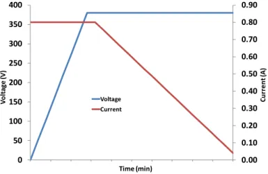
Figure 13 - Voltage waveform used in the PEO treatment. Ͳ indicates the period of the wave.
The process was controlled by current during the first moments until the voltage reach the maximum, from that moment on the process is controlled by voltage and the current starts to decrease with the time. This behavior is described in Figure 14.
Figure 14 - The graphs show the evolution of the voltage and the current with the time of synthesis.
Phosphate based electrolyte were used in this work, the composition of the electrolyte is present in Table 3.
Table 3 - Electrolyte composition
Electrolyte pH Conductivity (mS cm− 1)
12g/l Na3PO4 + 2g/l KOH 12.66 20.7
The pH was measured using Metrohm 691 pH meter and the conductivity using Mettler Toledo
Inlab 730 probe. V o lt ag e (v ) Time (ms) ton toff 0 Ͳ 0.00 0.10 0.20 0.30 0.40 0.50 0.60 0.70 0.80 0.90 0 50 100 150 200 250 300 350 400 C u rr e n t ( A ) V o lt ag e (V) Time (min) Voltage Current
19 2.5. Inhibitors intercalation
The intercalation of inhibitors was carried out using anion-exchange method schematized in Figure 9. Solution of 0.1M of MBT inhibitor was prepared with pH adjusted until the anionic form of the inhibitor is achieved (about 10.6).
The samples pre-treated with LDH were kept immersed in the MBT solution under stirring for approximately 12h under room temperature.
2.6. LDH synthesis on PEO surface
The LDH synthesis in pre-treated PEO was carried out only for so called “in situ 2” method and the experimental procedure is the same as the one used on in situ 2.
2.7. Thermal treatment
The thermal treatments carried out either on LDH specimens or in the non post treated PEO used the same sample holder immersed in a NaNO3 solution in the case of LDH treated samples and in deionized water in the case of the blank PEO. The thermal treatments were carried out in an oven at 90°C.
2.8. Techniques
The LDH structures were characterized using scanning electron microscopy (SEM) and X-ray diffraction.
a) Tescan Vega3 SB scanning electron microscope equipped with energy dispersive X-ray (EDX) spectrometer was used to analyze the morphology of the LDH structures and the PEO coatings. Cross sections and plan views of PEO coating were analyzed by SEM, the cross sections preparation started with the sample being mounted in epoxy resin and then by grinding with successive grades of silicon carbide paper and polished in water free solution with polishing diamond of 1 μm.
b) Bruker X-ray diffractometer with Cu Kα radiation (Cu Kα = 1.54056 Å) at a scanning speed of 0.01 s per point in scan range of 2θ from 5 to 65 degree was used to characterize the crystal structure of the LDH and to evaluate the intercalation with inhibitors. 2 theta range from 20 to 100 was used in order to characterize the parental PEO coating.
Corrosion behavior of the coatings was tested using electrochemical impedance spectroscopy (EIS).
20
a) Gill AC computer-controlled potentiostat where used with a Ag/AgCl reference electrode and a platinum mesh as counter electrode. Impedance measurements were performed in stirred aqueous 0.5 wt.% NaCl solution at room temperature with working area of 0.5 cm2. A sinusoidal perturbation of 10 mV RMS amplitude and a frequency sweep from 0.01 to 105 Hz. EIS measurements were performed at different times until 3 days for PEO coated specimens and until one day on the case of LDH coated specimens.
b) ZView software was used to analyze the EIS spectra. Fittings of equivalent electrical circuits were performed with the software with an error for individual parameters inferior to 5%.
21 3. Results
3.1. SEM
3.1.1. AM50 magnesium alloy
As indicated above the phases play an important role in the corrosion of the magnesium alloys, for that reason it is important to know the distribution and the type of intermetallics present in the alloy. To obtain information about the phases in AM50 EDS mapping were performed. Figure 15 shows the SEM images resulting from surface analyses of the AM50 magnesium alloy used in this work.
Figure 15- SEM image of AM50 magnesium alloy surface.
From the images it is possible to observe two different types of precipitates marked as “1 and 2” and “3 and 4”. EDS analysis was performed in the zone (see indication in the image) in order to identify the elemental composition of this inclusions.
Figure 16 shows the elemental composition for the tested zone.
22
Mn O
Figure 16 - EDS mapping results for AM50 magnesium alloy.
EDS results allowed to suggest, as shown in the Table 4, that phase “1 and 2” corresponds to β – Mg17Al12 phase and “3 and 4” corresponds to Al8Mn5 due to the presence of manganese in the mapping and the fitting of the ratios. Also Al8Mn5 phase is known for his polygonal shape37 that can be recognized in Figure 15 and 16. The Mg/Al ratio in the β phase (66/33 and 71/28) is a little bit higher than normal (17/12), this may happen due to the influence on the matrix. In the case of Al8Mn5 phase the ration Al/Mn (50/35 and 59/37) matches the normal ratio (8/5).
3.1.2. Characterization of LDH on the surface of AM50
SEM analyses represent a very important method to identify LDH structures due to the normally easy and fast identification of LDH like structures
Figure 17 shows the SEM images of the typical LDH flakes synthesized by in situ grown method.
Table 4 - Quantification of the elements resulting from EDS spectrum analyses. Element (%) Ratio Phase Al Mg Mn O β – Mg17Al12 - 1 33 66 0 1 2 β – Mg17Al12 - 2 28 71 0 1 2.54 Al8Mn5 - 3 50 1 35 13 1.43 Al8Mn5 - 4 59 1 37 4 1.59
23
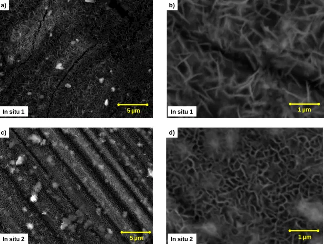
Figure 17 - SEM images of LDH synthesized by in situ 1 and in situ 2.
The SEM images of in situ 1 synthesis method presented in Figure 17 (a and b) clearly show homogeneous distribution flakes on the alloy surface, the flakes have similar shape to the ones found in LDH containing specimens. They appear to be perpendicularly oriented to the sample plane and have a size of approximately 1µm.
Similarly the results from in situ 2 (Figure 17, c and d) synthesis show the homogenous distribution of perpendicularly oriented LDH like flakes on the surface, with a typical size of 0.5 to 1.5 µm.
Analyzing the images from the two synthesis methods permit to observe some differences in the flakes. In situ 1 result in lower density of linear needle like shape flakes; in the case of in
situ 2 the flakes assume bigger diversity of shapes and sizes, presenting a random nonlinear
and longer form.
5 µm In situ 1 a) 1 µm In situ 1 b) 5 µm In situ 2 c) 1 µm In situ 2 d)
24 3.1.3. PEO treated on AM50 magnesium
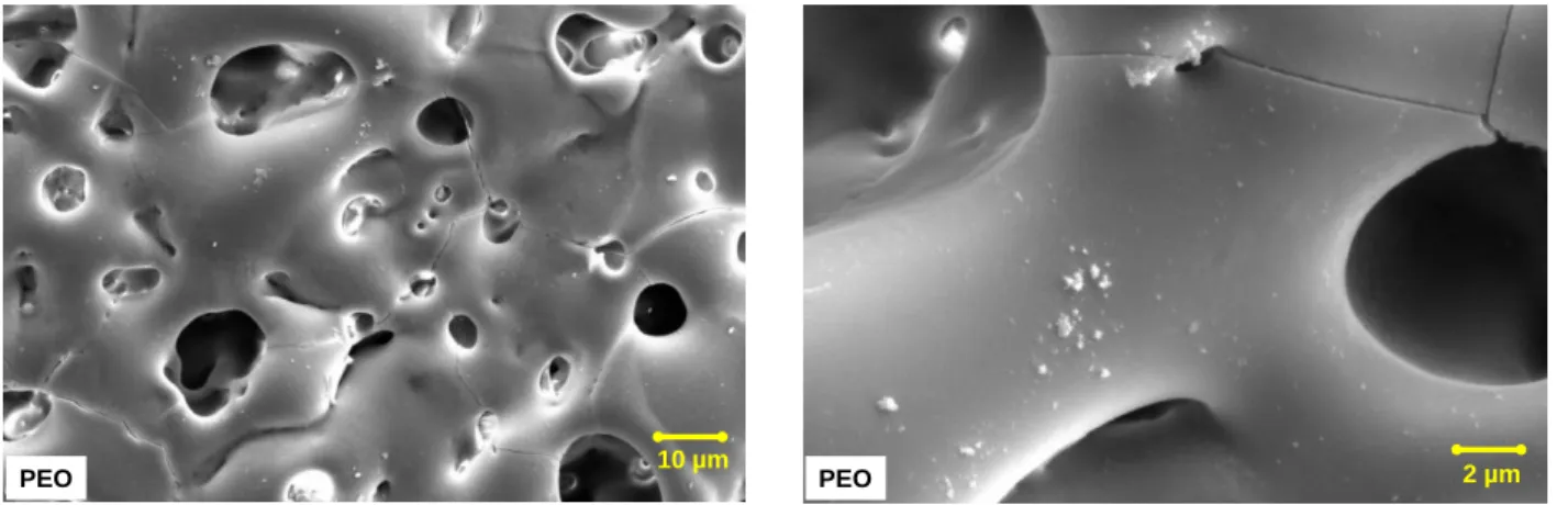
Figure 18 shows the SEM images of the PEO coating applied on the magnesium alloy surface.
Figure 18 - Plan view SEM images of PEO coated AM50 magnesium alloy. The images shows a surface of a PEO layer which contains porous with different shapes and sizes varying between about 1 to 20 µm. Cracks are also visible in the PEO layer. The PEO coating shows an apparently smooth surface with some particles smaller than 1µm deposited on the surface.
Figure 19 represents the SEM images of the PEO layer cross section.
Figure 19 - cross section SEM images of PEO coated AM50 magnesium alloy. One can see that a coating thickness is about 20 to 30 µm. The coating is not homogeneous, contains closed porosity and is detached from the metallic substrate at some places.
3.1.4. LDH treatment on PEO covered AM50 magnesium alloy
Figure 20 shows the SEM images of LDH treatment applied on PEO coated magnesium alloy. 10 µm
PEO PEO 2 µm
Detached
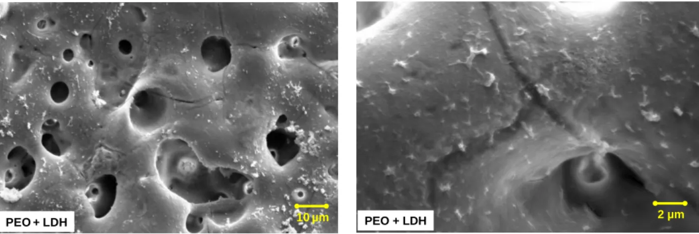
25
Figure 20 - SEM images of PEO coated magnesium alloy post-treated with in situ 2 LDH. After LDH treatment via in situ 2 method being applied, the surface clearly changed showing more and bigger (more than 1µm) precipitate agglomerates. The cracks appear to be sealed by a thin layer of what is suspected to be deposited LDH layer. However it can also be hydroxides precipitated during the thermal treatment process of the LDH synthesis. This hypothesis would be verified during next steps.
Figure 21 shows the SEM images of the PEO coating applied on the magnesium alloy surface which was undergone to the thermal treatment.
Figure 21 - SEM images of PEO coated magnesium alloy surface submitted to thermal treatment.
After thermal treatment the surface was changed and did not show any precipitates visible in the non post-treated PEO surface, however the surface still maintain the smooth appearance and porosity visible in Figure 18. When compared with the LDH treated sample (Figure 20) it is clear that the layer that seal the crack does not exist in the non LDH treated surface.
10 µm
PEO + LDH PEO + LDH 2 µm
20 µm
26 3.2. XRD
SEM analyses allow a fast identification of the structures, however, SEM by itself do not provide sufficient information to ensure the presence of LDH, due to that, XRD analyses typically represent a method that provide more information about the structures, like the high of the space between two LDH layers – the gallery high.
3.2.1. AM50 magnesium alloy
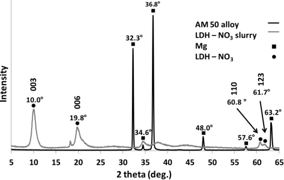
The XRD pattern presented in Figure 22 show the result of the analyses on magnesium alloy without surface treatment and with Mg – Al LDH – NO3 with the objective of identify the peaks from the alloy and the ones from the LDH. These results are in a good agreement with previously published32.
Figure 22 - XRD pattern of AM50 magnesium alloy and Mg-Al LDH slurry.
Two main peaks of LDH corresponding to the (003) and (006) reflections at 2 theta (2θ) equal to 10.0° and 19.8° are clearly visible. They correspond to the basal space of 8.8Å and a gallery high of 4.1Å (hydroxide layer thickness assumed as 4.77Å38).
Also two peaks corresponding to the reflections (110) and (123) at 2θ equal to 60.8° and 61.7° are visible for of Mg – Al LDH – NO3. These peaks are related to the composition of the cationic layer not with the intercalated species and can be a good indicator to confirm that the (003) and (006) reflections appear due to LDH structures.
5 10 15 20 25 30 35 40 45 50 55 60 65
In
te
n
si
ty
2 theta (deg.)
AM 50 alloy LDH – NO3slurry Mg LDH – NO3 34.6 32.3 36.8 48.0 57.6 63.2 60.8 19.8 10.0 003 006 61.7 110 12327
In the case of magnesium pattern the identified peaks start at 32.3° degrees. They are mostly far from the LDH – NO3 range of peaks, however, at higher 2 theta values the peaks at 57.6° and 63.2° are close to the peaks of the cationic layer. This fact should not represent a big issue taking into account that the Mg – Al ratio should not have a big variation maintaining the peak in the same position.
Figure 23 shows the XRD pattern resulting from the analyses on in situ 1 LDH – NO3 and in situ 1 LDH intercalated with MBT.
Figure 23 - XRD pattern of in situ 1 LDH – NO3 and in situ 1 LDH - MBT on the surface of the magnesium alloy.
The pattern represented in Figure 23 show that both LDH – NO3 and LDH – MBT have similar results showing peaks at around 7, 11 and 13 (2θ) degrees. The peaks marked as (003) and (006) were identified as LDH peaks, however they appear shifted to small 2 theta values, the result from the calculations of the gallery height are presented in Table 5:
Table 5 - Reflections data for LDH - NO3 and LDH – MBT
Specimen Reflection Angle (2 theta – deg.) Gallery high (Å)
LDH – NO3 003 7.6 6.9
LDH - MBT 003 7.1 7.7
Previous work32 proved that the gallery height depends on the intercalated anion size and orientation. In the same work was discovered that the gallery height were defined by and herringbone orientation of the MBT molecules inside Mg – Al LDH layers corresponding to a gallery height of 11.9Å. 5 10 15 20 25
In
te
n
sity
2 theta (deg.)
LDH - NO3 LDH - MBT 003 003 006 00628
This value is much higher than the one resulting from my measurements, however in the previous work the synthesis were carried out in an Mg to Al ratio of 2:1 and in the case of in
situ 1 synthesis that ration in not controlled and result from the availability of the cations in
the alloy. The ratio of in situ 1 can be defined as X:1 where X>>2, this produces less charged layers.
Analyzing the ionic radius of the bigger element of the intercalated molecule was found that the gallery height match reasonable the size of two molecules as were schematically represented in Figure 24.
Figure 24 - Schematic representation of a proposed organization of the anions inside the LDH gallery.
It is important to notice that the typical LDH structure peak at around 60° to 62° are not visible in the pattern possibly due to (1) the orientation of the flakes39 and (2) intensive peak of AM50 alloy in this region. However the SEM image a) and b) presented in Figure 17 shows clearly LDH like structures on the surface. It could be described by the parallel orientation of the LDH flakes to the surface.
Figure 25 shows the XRD pattern resulting from the analyses on in situ 2 LDH – NO3 and in situ 2 LDH intercalated with MBT. 6.85Å NO3 2.7Å 2.7Å NO3 5.4Å 7.67Å MBT 3.68Å 3.68Å MBT 7.36Å
29
Figure 25 - XRD pattern of in situ 2 LDH – NO3 and in situ 2 LDH – MBT on the surface of the magnesium alloy.
In the pattern represented in Figure 25 presents the peaks at 11.5° (003) and 23.4° (006) for LDH – NO3 and at 11.4° (003) and 23.3° (006) for LDH – MBT.
The 003 reflection for LDH - NO3 appears at 11.5°, this angle corresponds to a height gallery of 2.91Å, and following the same logic of In situ 1 analysis this gallery fits the ionic diameter of oxygen (2.7Å). A suggestion of the possible orientation of the NO3 molecule is suggested in Figure 26.
Figure 26 - Scheme of the suggested arrangement of NO3 inside LDH.
It is known that intercalation with MBT32 shift the XRD peaks to smaller angles due to the bigger size of the molecule when compared with nitrate that increases the gallery high of the LDH. Comparing the peaks from LDH – NO3 and LDH – MBT it is possible to see that in the case of LDH – MBT those peaks are slightly shifted to smaller angles, however, the reflection found at 11.4° corresponds to a gallery height of 2.99 Å. This gallery high is too small to accommodate the MBT molecule. Instead of MBT it is possible for the gallery to be intercalated either with carbonates or hydroxides.
5 10 15 20 25
In
te
n
sity
2 theta (deg.)
LDH - NO3 LDH - MBT 006 003 003 006 2.91Å30
The pattern represented in Figure 27 allows to analyze the phases formed during the PEO formation on AM50 surface and to prevent their possible overlay with the peaks of LDH on the surface (and contaminations formed during the synthesis).
Figure 27 - XRD pattern of PEO treatment applied on AM50 alloy.
Two phases were detected in PEO coating: MgO and Mg3(PO4)2 (indicated as ♦ and as ▲in the pattern, respectively). The presence of magnesium phosphate proves that the electrolyte was successfully incorporated in the coating.
Figure 28 shows the XRD pattern resulting from the analyses of in situ 2 LDH – NO3 and in situ 2 LDH intercalated with MBT applied on PEO pre treated surface.
The patterns represented in Figure 28 shows a main peak (reflection (003)) at 2 theta (2θ) equal to 7.17° and 7.75° for LDH – NO3 and LDH – MBT respectively. These angles correspond to a gallery height of 7.55Å of LDH – NO3 and 6.63Å of LDH – MBT.
In this pattern is not possible to identify any peak corresponding to the 006 reflection. The (110) and (113) reflections can be overlap by much more intense peak of Mg and MgO at the same angles (57.6° and 63.2°).
20 30 40 50 60 70 80 90 100
In
te
n
si
ty
2 theta (deg.)
♦ ▲ ♦ ♦ ♦ Mg MgO Mg3(PO4)231
Figure 28 - XRD pattern of in situ 2 LDH – NO3 and in situ 2 LDH – MBT applied on PEO coating.
3.3. Electrochemical Impedance Spectroscopy (EIS) 3.3.1. Impedance comparison of different coating
Figures 29 to 31 show the bode plots of the electrochemical impedance spectroscopy for the studied materials after different times of immersion in 0.5 wt% NaCl solution.
Figure 29 presents the comparison between the two different processes (in situ 1 and in situ 2) to form LDH on AM50 Mg alloy and the values of the module of the impedance at low frequencies are gather in Table 6.
With the analysis of the module of the impedance (Table 5 and Figure 29 (a-c)) it can be observed that for both treatments there is a decrease of the total impedance value with the time of immersion up to 10h due to the start and propagation of the corrosion process. However after 24h, there are no significant changes, probably due to the formation of corrosion products with some protective character.