Universidade de Aveiro Departamento deElectr´onica, Telecomunica¸c˜oes e Inform´atica, 2012
Eriksson Jorge
Melicio Monteiro
CloudMed – Plataforma de Comunica¸
c˜
oes para
Medicina
“It has become appallingly obvious that our technology has exceeded our humanity.”
— Albert Einstein
Universidade de Aveiro Departamento deElectr´onica, Telecomunica¸c˜oes e Inform´atica, 2012
Eriksson Jorge
Melicio Monteiro
CloudMed – Plataforma de Comunica¸
c˜
oes para
Medicina
Universidade de Aveiro Departamento deElectr´onica, Telecomunica¸c˜oes e Inform´atica, 2012
Eriksson Jorge
Melicio Monteiro
CloudMed – Plataforma de Comunica¸
c˜
oes para
Medicina
CloudMed - Open Communications in Medicine
Disserta¸c˜ao apresentada `a Universidade de Aveiro para cumprimento dos requesitos necess´arios `a obten¸c˜ao do grau de Mestre em Engenharia de Computadores e Telem´atica, realizada sob a orienta¸c˜ao cient´ıfica do Doutor Carlos Manuel Azevedo Costa, Professor do Departamento Eletr´onica e Telecomunica¸c˜oes e Inform´atica da Universidade de Aveiro.
o j´uri / the jury
presidente / president Prof. Dr. Antonio Manuel Melo de Sousa Pereira
Professor Catedr´atico do Departamento de Electr´onica, Telecomunica¸c˜oes e
In-form´atica da Universidade de Aveiro
vogais / examiners committee Prof. Dr. Carlos Manuel Azevedo Costa
Professor Auxiliar do Departamento de Electr´onica, Telecomunica¸c˜oes e
In-form´atica da Universidade de Aveiro
Prof. Dr. Rui Pedro Sanches de Castro Lopes
Professor Coordenador do Departamento de Inform´atica e Comunica¸c˜oes do
agradecimentos / acknowledgements
Quero agradecer ao meu orientador, Professor Doutor Carlos Manuel Azevedo Costa, pelo interesse, apoio, incentivo e simpatia mostrados ao longo de todo o trabalho. O seu sentido cr´ıtico e sugest˜oes/coment´arios contribu´ıram muito para a realiza¸c˜ao deste trabalho.
Quero agradecer ao Lu´ıs Basti˜ao, pela disponibilidade, colabora¸c˜ao e apoio que me deu ao longo destes meses de trabalho.
Ao grupo de bioinform´atica da universidade de Aveiro grade¸co por terem proporcionado a possibilidade de fazer parte desse grupo, que sempre me ajudou quando precisei.
A todos os meus colegas e amigos que encontrei ao longo deste percurso. Em especial, ao grupo de estudantes cabo-verdianos que esteve sempre comigo nesta fase da minha vida. Muito obrigado pela disponibilidade, apoio, incentivo e... amizade!!!
Por ´ultimo, o agradecimento mais importante... a toda a minha fam´ılia, que mesmo `a distˆancia, esteve sempre presente e muito apoiou para que eu pudesse superar esse percurso com sucesso!!! Especialmente, agrade¸co aos meus pais e irm˜aos por todo o carinho, amor, compreens˜ao, apoio e incentivo!!!
Resumo Os recentes avan¸cos das tecnologias de informa¸c˜ao e comunica¸c˜ao tˆem cri-ado novos cen´arios aplicacionais na ´area da telemedicina, nomeadamente na forma como integramos diferentes fontes de dados, como acedemos e partil-hamos estes recursos em ambientes m´oveis e como integramos ferramentas cooperativas inspiradas no paradigma das redes sociais.
Temos verificado nos ´ultimos anos a terciariza¸c˜ao de recursos computa-cionais, processo conhecido como Cloud Computing. Esta realidade cria novas oportunidades de explora¸c˜ao destes recursos para facilitar o acesso, partilha e integra¸c˜ao de informa¸c˜ao m´edica, em qualquer local e a qualquer hora. Mais ainda, a escalabilidade e fiabilidade oferecida por estas platafor-mas satisfazem os requisitos de servi¸co impostos a solu¸c˜oes telem´aticas na ´
area da sa´ude.
Esta disserta¸c˜ao teve como objetivo estudar o paradigma de software como servi¸co, suportado por uma estrutura em Cloud, tendo em mente a sua utiliza¸c˜ao em cen´arios de telemedicina e tele-trabalho. Muito concreta-mente, desenvolveu-se uma plataforma Web de servi¸cos orientada `as redes de imagem m´edica. Esta solu¸c˜ao disponibiliza um ambiente cooperativo in-ovador onde os cl´ınicos podem recolher dados, partilhar informa¸c˜ao e aceder remotamente a recursos imagiol´ogicos. Aspetos de seguran¸ca e interoper-abilidade com os atuais sistemas e normas foram alvo de particular aten¸c˜ao.
Abstract The recent technological developments in information and communications technologies are promoting new studies and research in telemedicine area, revolutionizing the access, integration and sharing of medical information. For instance, many systems have been focusing on ubiquity through the use of mobile computing and on enhance users cooperation through usage of social networking paradigms.
In this regard, the rise of new model of outsourcing computing resources, which is known as Cloud computing, creates new possibilities to explore their benefits to facilitate the sharing and remote access to medical information, anywhere and anytime. Moreover, the scalability and reliability offered by Cloud platforms fit well to the medical area requirements.
This dissertation aimed to analyze the current state of the art of Cloud Computing, namely studying their viability to support telemedicine and tele-working scenarios. The proposal was focused in the medical imaging field. The work resulted in a Cloud computing solution, following the software as a service model, to support cooperative tele-imagiology networks. It is a solution that allows users to setup collaborative environments in the field of imagiology, targeting the acceleration and improvement of decision-making processes. The proposal contemplates also other important issues like, for instance, security and interoperability with actual medical imaging systems.
Contents
Contents i
List of Figures iii
List of Tables v
1 Introduction 1
1.1 Motivation . . . 1
1.2 Goals . . . 2
1.3 Thesis outline . . . 3
2 State of the Art 5 2.1 Medical Environment . . . 5 2.1.1 Telemedicine . . . 5 2.1.2 PACS . . . 8 2.1.3 DICOM . . . 10 2.2 Cloud Computing . . . 19 2.2.1 Overview . . . 19
2.2.2 What is Cloud Computing? . . . 19
2.2.3 Deployment Models . . . 21
2.2.4 Services Layers in the Cloud . . . 22
2.3 Extensible Messaging and Presence Protocol - XMPP . . . 24
2.3.1 Definition . . . 24
2.3.2 Architecture . . . 24
2.3.3 Streaming XML . . . 26
2.3.4 Extensibility . . . 31
3 CloudMed Proposal Definition 33 3.1 System requirements overview . . . 33
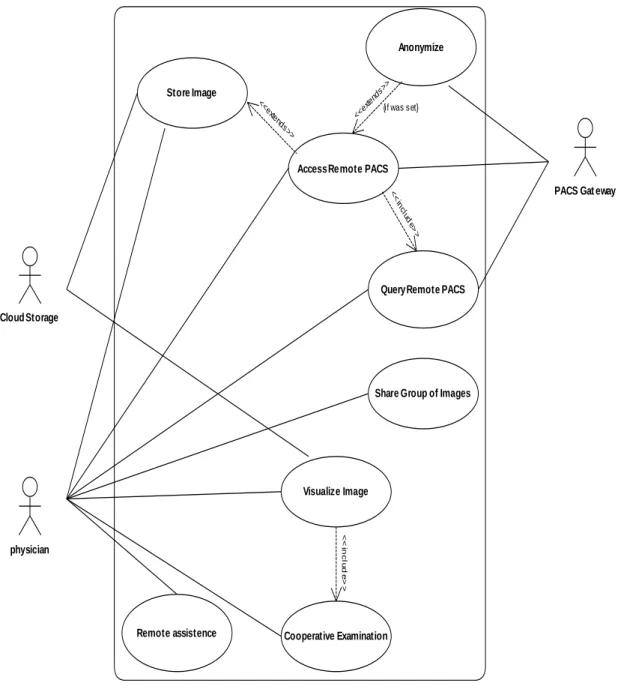
3.2 Functional Requirements . . . 34
3.3 Non Functional Requirements . . . 36
3.3.1 Information Accessibility and Availability . . . 36
3.3.2 Information Security . . . 37
3.3.3 Service reability . . . 37
3.3.4 Service scalability . . . 37
3.4 System Modeling . . . 37
3.4.2 Data Model . . . 45
3.4.3 Architecture . . . 47
4 System Implemantation and Results 49 4.1 CloudMed SaaS - Computer Supported Social Network for Teleradiologia . . 49
4.1.1 Message-oriented Middlware eXtensible CloudMed Communication Protocol - XCMCP . . . 50
4.1.2 XMPP server - Openfire . . . 59
4.1.3 Personal Remote Archive - PRA . . . 60
4.1.4 System Core Organization . . . 61
4.2 Medical Management Information System Gateway - DICOM Gateway . . . . 68
4.2.1 CloudMed PACS Gateway architecture . . . 68
4.2.2 XMPP interface . . . 69
4.2.3 DICOM interface . . . 70
4.2.4 Folder synchronization . . . 72
4.2.5 Anonymous Images . . . 73
4.3 CloudMed Web2.0 Client . . . 74
4.3.1 JavaScript XMPP Client . . . 76
4.3.2 Html5 and JavaScript User Interface . . . 78
4.4 Results . . . 81
5 Conclusions 91 5.1 Future work . . . 92
List of Figures
2.1 PACS system architecture . . . 9
2.2 SOP Class structure: DIMSE services applied to IOD instances . . . 11
2.3 DICOM information hierarchy. . . 12
2.4 DICOM Object struct . . . 13
2.5 DICOM Object Data Element . . . 14
2.6 DICOM SCU-SCP model . . . 15
2.7 DICOM services and network entities . . . 15
2.8 DICOM C-Store . . . 16
2.9 Wrapping the C-Store service in the C-Get service . . . 17
2.10 C-Move with three entities . . . 18
2.11 DICOM MWL example . . . 18
3.1 System use cases. . . 36
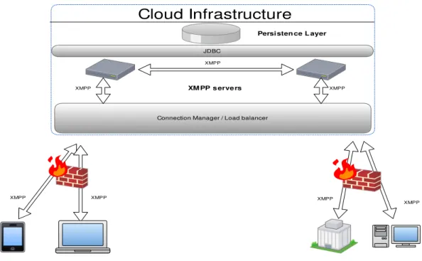
3.2 Scale XMPP infrastructure with multiple servers . . . 39
3.3 The diagram of how business logic layer interacts with the persistence layer . 40 3.4 Holding medical image data in a private Cloud. . . 40
3.5 Deploying storage and service in a public Cloud . . . 41
3.6 Flowchart of medical image storage in the cloud. . . 42
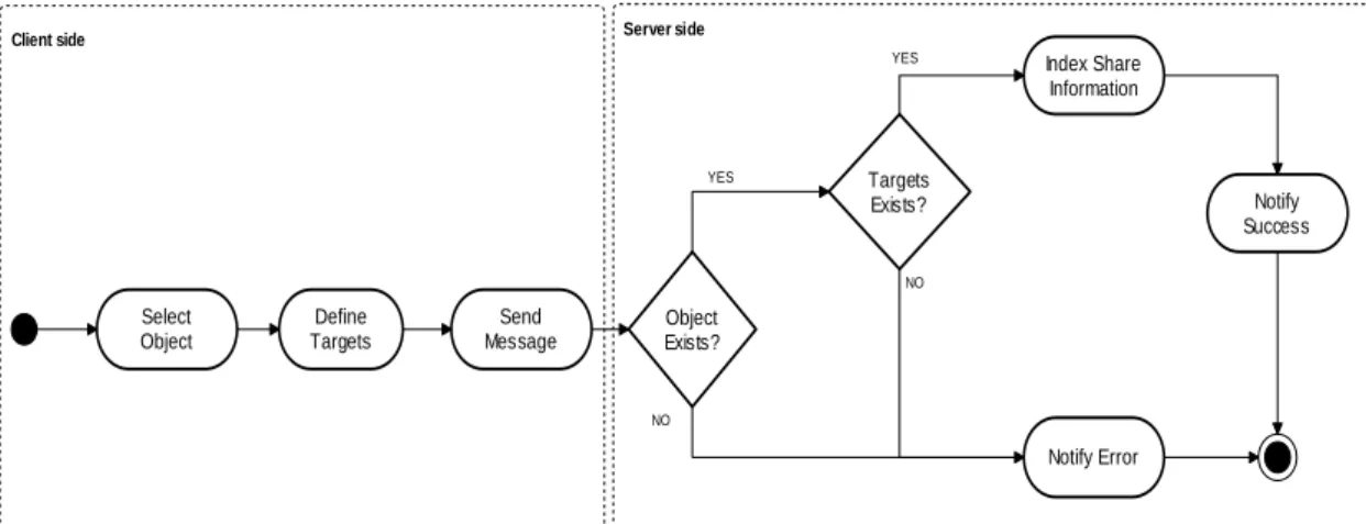
3.7 Folder sharing diagram . . . 43
3.8 Firewall bypass using XMPP server as Cloud relay . . . 44
3.9 Cloud relay gateway firewall diagram . . . 45
3.10 Remote action execute diagram . . . 45
3.11 CloudMed system data model diagram . . . 46
3.12 Physical Data Model of file shares and file ownership . . . 47
3.13 Physical Data Model of proxy firewall rules . . . 47
3.14 System architecture diagram . . . 48
4.1 Remote repository manage sequence diagram . . . 51
4.2 Personal remote archive diagram . . . 60
4.3 Archive manager diagram . . . 62
4.4 Remote Archive plugins implementation . . . 63
4.5 Extension packet handle diagram . . . 64
4.6 Uploading files to Cloud storage . . . 65
4.7 File upload authentication . . . 66
4.8 Download file diagram . . . 67
4.10 CloudMed PACS gateway components diagram . . . 69
4.11 Gateway XMPP entities class diagram . . . 70
4.12 DICOM layer class diagram . . . 71
4.13 DICOM Query/Retrieve sequence diagram . . . 72
4.14 Sequence diagram of folder synchronization . . . 73
4.15 Anonymization rules update via PubSub mechanism. . . 73
4.16 Image upload with anonymization capabilities. . . 74
4.17 Web application MVC design pattern . . . 75
4.18 Web application layout prototype . . . 75
4.19 XMPP JavaScript client organization. . . 77
4.20 WebRTC session establishment. . . 81
4.21 Remote repository in the Cloud. . . 82
4.22 Sharing files with colleagues. . . 83
4.23 Accessing shared files. . . 83
4.24 collaborative tools. . . 84
4.25 Synchronizing data from the Cloud . . . 85
4.26 Embedded HTML5/JS DICOM viewer . . . 86
4.27 Searching on remote PACS archive from web application . . . 87
4.28 Select and retrieve images from remote PACS arhive . . . 87
4.29 Sharing PACS with colleagues . . . 88
4.30 Gateway graphical user interface. . . 89
List of Tables
2.1 DICOM DIMSE services . . . 14
2.2 XMPP Presence types used in subscription. . . 29
2.3 XMPP extended presence . . . 29
2.4 XMPP Presence stanza types . . . 30
2.5 XMPP Info/Query stanza types . . . 31
3.1 List of functional requirements. . . 35
Chapter 1
Introduction
1.1
Motivation
The progress in medicine gained an important impulse with the evolution of informatics and telecommunications. As result of the adoption of the technology in the health care insti-tution, emerged the telemedicine that is a way to provide health care services at a distance, which more has been leveraged by the evolution of informatics and telecommunications. Due to the fast evolution of informatics and telecommunications, and reduction of its price, the telemedicine scenario is being widely explored [1–3] by many investigators and health care service providers, with the aim to take the best advantage from the contemporary technology for improve services provided by health care institutions. This tremendous evolution of tech-nology creates opportunities to improve and even create new telemedicine services. Moreover, the distinction of telemedicine will disappear by virtue of its pervasiveness. Technology appli-cations will continue to evolve rapidly and will become more integrated and ubiquitous. This progress will be strongly impacted by wireless and broadband innovations. These changes promote portability and the seamless integration of technology into daily life. So, in time, telemedicine applications will even evolve beyond Internet-based opportunities. They will become wireless, portable and eventually, wearable.
The improving of telemedicine services’ comprisement, using electronic information and communications technologies to leverage and enrich its quality of services when the distance barrier separating health care participants is a considered factor, has been successfully ac-quired with the embrace of the new technologies in this purpose. Thus, probably, these evolutions had and will continue to have a vast impact in the services provided by health care institutions. With the introduction of technologies at service of medicine became easier and efficient the management of all the data that is generated by health care institutions, taking advantage of specialized systems to manage these data and also it become easier and faster the way that the information is exchanged and transmitted. Focusing in the medical imaging area, it is possible to identify some informatic systems that were developed to in-crease the efficiency of how the medical images data are managed and transmitted inside a health care institution. To deal with the huge amount of data, which can reach Terabytes of information generated by health care institutions, was developed the PACS system. PACS systems are widely adopted by health care institutions to implement an informatic system that can be efficiently managed, allowing the standardization of the data acquisition, storage and transmission. Nevertheless, the investigation in medical informatics systems is active and
investigators are focused in explore the technologies evolutions in health care area, thus it is common to appear new systems (e.g. RACS, cloud-based Virtual Radiologic-vRad etc) that are proposed to be applied in the broad area that is medicine.
The developments already done in the medical informatics’ area show that the application of informatic technologies in the medical area is an added value, so it is important to con-tinue to investigate the application of the new emergent technologies in this area. Moreover, evolution of the technology is being fast, thus new concepts are emerging and its application in medicine can be very important to improve actual services.
This thesis lays on the new technologies to create a new service based on Cloud computing to leverage telemedicine. Furthermore, this work will explore how the utilization of Cloud computing technologies can be efficient and an asset to telemedicine services, by taking advan-tage of its features like, for instance, outsourcing of computation and storage, information’s access, availability, scalability, etc. It will be proposed a Cloud-based system to provide a ser-vice that can be used by radiologists to do telework through a cooperative environment. The service will allow radiologists to share medical images with colleagues and to interact with each other in examination of a given study, thus creating a channel which may be used to get a second opinion in an examination or to interact with an expert in a given area. Furthermore, the resulting service might be used to provide remote support to health care centres that does not have specialized radiologists, to integrate distributed medical information sources or in educational purpose.
1.2
Goals
To implement Cloud based software as a service is necessary to analyse the Cloud infras-tructures and how they are deployed. Thus, just deploy an infrastructure in the Cloud does not mean that this infrastructure inherits Cloud characteristics like, for instance, scalability. Obviously, to implement a medical informatics system is necessary to take care of some issues related with the data security, because these kinds of systems deal with sensitive data, and with the availability of data any time a physician tries to access it. Also, to access data from inside a health care institution may bring some issues to solve related with firewalls. In general, the goal of this thesis is to create a fully integrated distributed system based on Cloud that tackles the presented problems. Moreover, it must be Web 2.0 compliant.
Accordingly, this work’s main goals are the following: • The study of Cloud computing fundamentals • The study of teleimagiology services.
• The study and development of a Cloud based system for teleimagiology.
• The integration of Cloud based infrastructure with actual medical imaging data sources. All the broad environment of new opportunities, which is being provided by new tech-nologies, are ready to be explored, thus this is the challenge that this work aims to fulfil in order to provide better services, any-time and anywhere.
As result, it is expected to achieve a system well supported by technologies, with a lifecycle well defined, that should be provided as a service in the Cloud to serve radiologists, allowing the improvement of the workflow and dataflow in telework.
1.3
Thesis outline
This dissertation is organized according to the following structure:
Chapter 2 presents the medical scenario where this these is inserted. It is made a brief in-troduction to telemedicine, focusing on teleimagiology services. There is an overview of actual applications of teleimagiology services, the way new technologies are improving those services and empowering the appearance of better systems. Furthermore there is the presentation of Picture Archiving and Communication System (PACS), where is showed its importance to the revolution of imagiology. In addition, this chapter talks also about Cloud computing paradigm, depicting some deploying models and services available in the Cloud. Moreover, there is an explanation of how Extensible Messaging and Presence Protocol (XMPP) can be useful as message-oriented middleware for creation of collaborative systems.
Chapter 3 shows the system requirements and how it was modelled. First there is an identification of all functional and non-functional requirements defined for the system to be developed and, from those requirements, is made a proposal for implementation. There is an explanation of how this proposal designs the system’s workflows and, also is presented a data model and architecture to support it.
Chapter 4 explains the implementation decisions. Meanwhile, it is presented a plug-in based system which empowers CloudMed Software-as-a-Service implementation. Further-more, there is the presentation of the messages-oriented middleware that supports the system and, how was implemented CloudMed PACS gateway to enable the creation of an interface between the Cloud XMPP network and the PACS network. After, is explained the imple-mentation process of CloudMed Web2.0 application. And finally, it is presented the results obtained with the implementation of CloudMed system.
Chapter 5 presents the conclusion of this thesis and, there is also an analyse of the system’s strength, weakness and future works.
Chapter 2
State of the Art
In this chapter, will be presented the technologies that currently are supporting solutions in telemedicine, which enable the storage and access to medical images. Besides the analysis of contemporaneous telemedicine, it will be contemplated some Cloud service-oriented archi-tecture, which will be a mainstay for the creation of the solution proposed in this work and it will be exposed a protocol that can be an asset to create collaborative systems.
2.1
Medical Environment
2.1.1 Telemedicine
Telemedicine [4] is based on the use of informatics and communications technologies to allow doctors to examine, monitor, investigate and treat patients who are physically apart, or do not have the availability to travel to the health center. This is an area of medicine that has captivated the interest of several researchers in recent years. The concept of telemedicine has become very important to medical science. In many countries where the population is highly dispersed, with a low population density in certain regions, telemedicine emerges as a vital medium that can save lives, because it is through those services that can get to anywhere the qualified health services. Also in countries where the demands on hospitals are increasing, telemedicine can be a solution that involves the use of current information technologies to create solutions that make it easier for hospitals to make available therapies and tele-consultations for patients, thus decreased the percentage for use of the physical space available in hospitals. Such means can also be used to assist doctors in diagnosis of medical images by remote diagnostics and / or teleconsulting.
With the advancement of information technology and telecommunications, telemedicine is no longer a forthcoming idea and the concept is becoming more mature and very important for institutions that provide health care. Telemedicine can be seen as a leverage of the quality and availability of services provided by health institutions and, it will be fundamental in the future to enable hospitals provide medical services to patients overcoming physical barriers, eliminating the need for patient travel, enabling hospitals to make available high quality services at distance.
Teleimagiology
Teleimagiology is a branch of telemedicine which has a wide use in medicine. It is based on medical images in digital format, such as CT (computed tomography), US (ultrasounds), MR (magnetic resonance), etc, which are sent from one location to another in order to be analysed and / or consulted by specialists. The traditional teleimagiology consists of three basic elements: the station that sends medical images, a transmission channel and receiving station.
This medical service is supported by currently available technologies and telecommunica-tions, where images are obtained from digital medical equipment with capacity to produce images in digital format. They can be transmitted to any location via a network connec-tion, like for instance, telephone lines POTS (Plain old telephone service), LAN (Local Area Network) or WAN (Wide Area Networks).
The first steps of teleimagiology dates back to 1929 when the first medical image was transmitted; it was transmitted a dental x-rays through a telegram to a distant location [5].
Currently teleimagiology is widely used for training new radiologists, for teleconsulting in cases where it is needed a second opinion in medical image analysis, for provide medical assistance to regions of difficult access, for assist and train radiologists in developing countries, etc.
The integration of radiological equipment from diverse manufacturers in the same teleima-giology network, is a task that is backwards some problems and challenges. The need for interoperability among all radiological equipment is very important in the hospital network, so was developed DICOM standard. This standard defines how medical images are acquired, transferred and stored. The format defined by the DICOM standard will be analysed in more detail in section 2.1.3.
Thanks to the DICOM is empowered the interoperability between equipment from differ-ent manufacturers, which facilitates the transfer of medical images from one place to another. The transmitter station, which is part of teleimagiology systems, is responsible for the con-version of medical images, for example, x-ray, in digital format and the compression of the images taking into account the desired resolution and bit rate available. The data compres-sion is possible using the characteristics of the DICOM coding format, allowing lossy and lossless compression, where the degree of loss of information is variable which depends on the modality used. This compression reduces the density or number of bits per pixel and, consequently, there is degradation in image resolution. Ideally, in teleimagiology would not be necessary compression of images, if they are obtained by high-resolution equipment and high-speed transmission; however this is not possible due to technological limitations. In this sense the optimization of a parameter implies the degradation of other (e.g. increasing the speed of transmission often involves an increase in the level of compression and the reduction of the images’ resolution).
As regards the receiving stations, they should also be connected to a high-speed network point. Besides, the quality of the monitors for display of medical images is also an important feature to facilitate diagnosis. The receiving stations are usually equipped with large monitors with good pixel resolution [6]. Another important requirement is the ability to support the monitor split screen so as to enable the radiologist to visualize more than one picture at a time in order to compare different images. The quality of the monitor’s brightness is also very important for the radiologist because the monitors with greater vividness allow the radiologist to better identify regions of interest in the image that is analysed.
For the analysis of medical images is used specialized software with features that are an asset to the evaluation and decision making by the physician. Most of the software provide simple feature which let physicians to manipulate the gray level of the image, zoom, etc. But, there are expertise software with specialized functions available, such as allowing the physician to enhance edges, display histogram equalization, add notes to the relevant parts of the image, map a grayscale image, apply filters, etc. The value of the functionalities provided by software, which allow physicians to analyse medical images, in teleimagiology depends on the users’ need and the type of images analysed.
The use of teleimagiology for enhance the quality of services provided by hospitals is an increasingly realistic scenario. Currently, there are several applications of teleimagiology, among which we can list the following:
• Radiologist on call:
This is an application of teleradiology that allows a doctor to get at his residence through a portable device, patient’s medical images that are transmitted from the hospital / clinic to be analysed remotely. This service allows the radiologist instant consultation with the attending physician, thus leading to the improvement of services provided by health centres.
• Primary care physicians in rural areas:
The technologies allow doctors from remote clinics that are primary care provider in rural areas, to easily and quickly send medical images of patients, to be consulted and evaluated by experts who are in remote health centres.
• The medical consultants requiring remote subspecialty of radiology:
Often it is necessary the evaluation of medical imaging by sub-specialists in certain areas of radiology. Through teleradiology this process is speed up because the doctor in a health center can easily send a set of a medical imaging study to be evaluated by a radiologist who is sub-specialist in a particular area (e.g., Paediatric Radiology). The data’s flow and its availability are very important in telemedicine to raise a solid and useful system [7]. In [8], a system called MIFAS (Medical Image File Accessing System) was created focusing their objectives to solve the problem of medical information exchange, store and share between different hospitals. It was used a Cloud based architecture, where they use Apache Hadoop and co-allocation mechanism to implement a distributed file system.
Also, in [9] authors analysed the advantage of using the new Cloud computing paradigm to improve health care systems. They implemented a PACS on Cloud where was promoted the Cloud’s elasticity and scalability, providing universal access to the information and increase the data availability anywhere, any-time. The system uses the concept of “PACS-as-a-service” and the authors say that is possible to reach interoperability with DICOM devices through a PACS Cloud Gateway. Besides problems related with information access, availability and interoperability, the proposed architecture has also some concerns with security issues. All data stored on the Cloud are ciphered; furthermore the keys that are used to cipher the data are stored on a trustable provider or in-house, so the cloud providers are not able to decrypt the files and access the clear content.
There are some works that outlines others features like, for instance, user interactions, and what they can do with data available on Cloud. Many systems have been focusing on ubiquity through the use of mobile computing. For instance, there are systems that can be
used by physicians to manage patients’ health records and medical images using the emerging mobile computing [10, 11].
The authors on [11] were concerned with actual mobiles phones and tablets limitation like, for instance, the reduced computational power, limited storage and memory to implement a three-tier architecture. They have been working around these problems, aiming to enable users mobile access to DICOM medical images. Problems related with network management policies at healthcare network, that usually only allow protocols like HTTP or IMAP also influence telemedicine systems architecture. However, relays hosted in a Cloud service can be a work around to enable system connectivity [11], due to the fact that the relay is the responsible for the communications between Internet connected client device and a corporate PACS.
In the past, a system [12] created synchronous collaboration mechanisms among the med-ical staff, improving telemedicine services and real time collaboration. The developed system highlighted the importance of CSCW (Computer-Supported Cooperative Work) [13] on E-Health [4, 14] platforms. They provided synchronous and asynchronous collaborative capabil-ities through components like multimedia messaging, forum, video-conferencing tool, virtual shared space, on-line focus group, and so forth. Nevertheless, that system works only for a single institution.
The proposed on this dissertation work aims to analyse and find some path to improve the communication between multiple institutions and telework, providing some useful features like messaging and presence, collaborative and cooperative work in a Cloud-based platform.
2.1.2 PACS
Nowadays, the hospitals have recognized the benefits of computing and technology for the management of medical information. Three decades ago came the first PACS (picture archiving and communication system) [6], that have revolutionized radiology and somehow all of medicine. Due to the large amount of data generated in the imaging area of radiology [6, 15] by some medical exams as cardiovascular ultrasound (US), angiography (XA), digital mammography, computed tomography (CT), positron emission tomography (PET), etc, there was the need to create an infrastructure that provides a manner that clearly defines how it is stored and accessed medical images obtained from the hospital network [6]. The use of PACS in a hospital network facilitates and speeds up the way medical data is transmitted and accessed. PACS systems use the standard format defined by DICOM standard [6, 16] to store and transmit medical images in order to support interoperability between equipment from different manufacturers.
As an overview, it can be said that PACS encompasses technologies used for the acquisi-tion, archive, distribution and visualization of a set of digital images using a computer network for diagnosis and revision in dedicated stations (Figure 2.1).
Figure 2.1: PACS system architecture
Components
Typically, a PACS is composed by four components [6]: gateway for medical imaging acquisition, PACS archive server, workstations for data visualization, application servers.
Beyond that components can be found some PACS application servers and access gateways which are used to connect to the information systems from other institutions that provide health care.
Gateway for data acquisition on medical imaging
The acquisition of medical imaging is one of the main tasks of a PACS system. Due to some problems related with equipment from different vendors is required the existence of gateways for data acquisition on medical imaging system. The existence of the gateway is a need because each vendor implements its own protocol in accordance with the statement made by the DICOM standard, and also because there is a need for communication between different PACS systems. Gateways consist of an important point of the system where is made the formatting of medical images from given radiological equipment to a standard format used to communicate in the PACS system, which is compliant with the format defined by the DICOM standard, and then these images are forwarded by the gateway to the PACS archive server or a workstation for viewing.
The gateways are placed between the units responsible for obtaining medical images of each modality and the rest of the PACS system. They interact directly with the image acquisition equipment that is connected to the medical imaging modalities.
PACS archive server
The PACS archive server is the engine of any PACS system. This server consists of high-performance computers. It is composed by a database where information about patients are indexed, from the HIS and RIS, and a file system where files are stored in the short / long term or permanently.
In a PACS, the PACS server is responsible for receiving the images of medical examinations and updating the management system database. In addition to the function of obtaining medical, the server can include others functions like, for instance, compression of images, check the integrity of files, extracting information that describe the examinations received through the header of DICOM images, communication interface with applicational PACS servers, etc.
Workstations
The workstations include communication with the PACS system network, a monitor for vi-sualization of images and image processing software. Some workstations may also be equipped with a local database or not, depending on the needs. The workstations that have a local database are usually equipped with many features for medical image processing and need only to communicate with the PACS server sporadically as they can keep information in the local database. On the other hand, the workstations are not equipped with a local database need only some basic processing functions and are constantly being aided by the PACS server.
Radiologists use the workstations to make medical diagnoses of radiological images. They have available a set of features that can be used to interact with the PACS archive server or even other PACS components. These features include the possibility of select the images he wants access through DICOM query / retrieve, measurement tools that can aid him in image interpretation and diagnosis, the accumulation of all relevant information and images of a particular examination from a given patient, etc.
Application Servers
The application servers are connected to the PACS server and, for instance, they can be used to filter the data retrieved from PACS server, with the intention of satisfying a particular purpose, or to make any desired data processing. In the PACS, it is possible to find various types of application servers. For example, it may have application servers whose purpose is to create a web service for viewing medical images, creating an electronic patient record (EPR) based on images, create an application server for educational purposes, etc.
2.1.3 DICOM
DICOM [16] is an international standard that defines data formats, storage organiza-tion and communicaorganiza-tion protocols of digital medical imaging, which was approved by ACR (American College of Radiology) and NEMA (National Eletrical Manufactures Association) in October 1993. This standard has emerged as a result of the appearance of many equip-ments with capacity to acquire, transfer and store data imaging, and the consequent need to standardize the communication processes of these devices on the network.
The ACR and NEMA have developed a set of standards, recommendations and guidelines that allow the communication of information between different digital imaging equipments,
which is the basis of the strong development and expansion of PACS.
The Digital Imaging and Communications in Medicine (DICOM) [6, 16] emerged in the early 90’s, and was released in 1993 a new version consisting of 13 parts. But in its present DICOM version 3.0 [16] is divided into 18 parts that include 160 supplements on specific aspects of one or several parts of the standard. Thus the DICOM has become the interna-tional standard that defines formats and communication protocols of medical digital images. It defines the semantics of the commands and associated data so that different devices can interact. The DICOM standardizes the entire set of methods of storage and transmission of digital medical images. Thus, it enables the communication of medical information be-tween digital equipment (from several different manufacturers), such as imaging modalities, workstations, printers, servers, etc.
DICOM Information Model
DICOM Information Model is the model used by DICOM standard to represent real world information like patients, studies, medical devices, and so on. All real-world data are represented in DICOM as objects with respective properties or attributes. DICOM objects and attributes are standardized according to DICOM Information Object Definitions (IODs). IODs are collections of attributes, used to describe each particular data object. For example a patient IOD can be described by name, medical record number (ID), sex, age, and so on.
DICOM operates guided by a service-rendering model where DICOM applications provide services to each other. Moreover, there is an association between particular service types with the data (IODs) that they process. DICOM calls these associations Service-Object Pairs (SOPs), and groups them into SOP Classes (Figure 2.2).
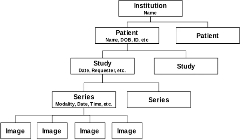
Figure 2.2: SOP Class structure: DIMSE services applied to IOD instances [16]. All DICOM commands and most DICOM data attributes are always bonded with the four-level information model represented by Patient-Study-Series-Image hierarchy (Figure 2.3), wherein:
1. One patient may have multiple studies.
2. Each study may include one or more image series. 3. Each series has one or more images.
DICOM hierarchy reflects what happens in the real world. For example, a patient goes to a hospital and can make several studies (for example, MR, CT, and ultrasound exams)
and these studies may have multiple image series (coronal, axial, with or without contrast, with varying imaging protocols, and so on). And each series will have one or more images associated with it.
To identify patient, study, series, and images, the DICOM hierarchy defines UID (Unique Identifier) to each hierarchy level. The patient level is identified by “Patient ID” (all patients should have IDs that identify them uniquely). All DICOM element is identified by a tag. The definition of DICOM tag will be presented DICOM Data Format 2.1.3 subsection. The “Patient ID” element is stored with the (010,0020) tag, making this tag required for any type of imaging. The same principle applies to the other three levels of the Patient-Study-Series-Image hierarchy: at the Study level, each study has its unique “Study Instance UID”, (0020,000D); at the Series level, each Series has its unique “Series Instance UID” (0020,000E); and at the Image level, each Image has its own “SOP Instance UID” (0008,0018).
Institution
Name
Patient
Name, DOB, ID, et c Patient
Study
Date, Requester, etc. Study
Series
Modality, Date, Time, et c. Series
Image Image Image Image
Figure 2.3: DICOM information hierarchy.
DICOM Data Format
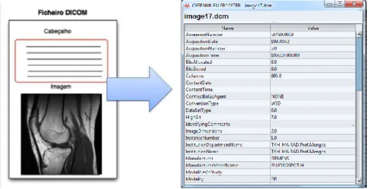
DICOM files support multiple types of elements of medical information, such as several medical imaging modalities, waveforms, clinical structured reports, etc. Every DICOM file has a header that contains metadata, used to represent the DICOM Information Model [6], including information related with patients, clinic staff, institution, equipment and conditions of the examination, etc. The DICOM Information Model [6] contains the data that make correspondence with the real world information (Figure 2.4).
DICOM groups information into data sets. The each data set of a DICOM file contain some specific information, for example, within a DICOM file can be found the patient ID, institution name, modality type, digital medical image bytes. Moreover these data set can never be separated from by mistake.
A DICOM data object is formed by many of attributes, and one special attribute that contains the image pixel data. A DICOM object contains only one pixel data attribute. That can correspond to a single image. But in some modalities, this attribute may contain multiple frames, in order to storage cine loops or other multi-frame data. Moreover, DICOM object’s pixel data can be compressed using a variety of standards, including JPEG, JPEG Lossless, JPEG 2000, MPEG3, MPEG4, etc.
A DICOM object Data Element is structured as follows: GROUP (2 bytes) ELEMENT (2 bytes) VR (2 bytes) LengthInByte (2 bytes) Data (variable length). it can be encoded using different Data Element encoding schemes. With Explicit value representation (VR) type of Data Elements, where VR defines the element’s value representation (that can be DA for date, TM or time, PN for patient name, etc). Also, DICOM objects can have Implicit Data Elements wherein VR is not present [17].
Figure 2.4: DICOM Object structure
DICOM data packing follows the TLV format (Tag, Length, Value) as shown in Figure 2.5. The tag has 4 bytes, where the first 2 bytes are for the group and the last 2 byte for the element, thus representing the “(group, element)” tag used to identify a given Data Element. For example, Patient Name tag has the group value 0x0010 and element value 0x0010, thus it is represented as (0010,0010) tag.
As expressed, the Value Representation (VR) field is used to define the encoded type for a given element and it depends on the element tag. For instance, VR fields can have the given value DA for Date, TM for time, OB for Object Binary, etc. Some elements can have implicit VR because it is possible, according with tag value, consult a DICOM Dictionary that defines what type an element stands for.
The Length field is used to define the length in bytes of element’s value field. This value depends on the tag value. At last, the element has the value field, which contains the data that is stored in the element (e.g. image pixel data, patient birthday, patient name, patient ID, etc).
As can be verified in Figure 2.5, DICOM files are formed by a sequence of Data Element or TLV sequence. Each TLV represents an attribute. Also it is possible to create private tags and extend DICOM protocol capabilities to represent extra real world information.
Figure 2.5: DICOM Object Data Element
DICOM Communications
DICOM provides of many different services, most of which involve transmission of data over a network. The protocol uses TCP/IP to establish a reliable connection between end-points. As others protocols like, for instance, SMTP, HTTP, FTP, etc, DICOM only adds its own networking language (at application layer) over TPC/IP. This language consists of high-level services, DICOM Message Service Elements (DIMSE). DICOM communication
fol-DIMSE C-Store Request / Response C-Find Request / Response C-Get Request / Response C-Move Request / Response C-Cancel Request / Response C-Echo Request / Response
N-Event Report Request / Response N-Get Request / Response
N-Set Request / Response N-Action Request / Response N-Create Request / Response N-Delete Request / Response
Table 2.1: Create DIMSE services associated with composite SOP classes (DIMSE-C) and services associated with normalized SOP Classes (DIMSE-N).
lows the client/server model. In DICOM network, it can be found the Service Class Provider (SCP) and Service Client User (SCU). SCP or SCU is used to denominate a kind of device, according to its role in the network (Figure 2.7). An entity can play SCP or SCU application roles to communicate with each other (Figure 2.6). For instance, a modality or workstation
that produces or consumes images, has to interact with PACS Archive. In this case the modality or the workstation is SCU and the PACS server belongs to SCP.
In DICOM network, each device has an Application Entity Title (AETitle) that identifies it. AETitle is used to address entities into a DICOM network. To access to any DICOM service or to communicate with any DICOM device first must be created a DICOM associa-tion, in order to create a channel for information exchange. In the establishment of a DICOM association, there is negotiation of several parameters, such as, encoding (ex. little-endian, big-endian), image compression formats, what kind of information will be transferred, and the duration of the association. After the negotiation, the service commands are executed between SCU and SCP to perform the service goal.
Figure 2.6: DICOM SCU-SCP model [16].
Store
The DICOM Store service is used to send images or other persistent objects (structured reports, encapsulated PDFs, etc.) to a PACS archive or workstation. This service uses C-Store (Storage SOP) command to move DICOM images between the entities, over a DICOM network (Figure 2.8).
Figure 2.8: DICOM C-Store [16].
Storage Commitment
The DICOM storage commitment service is used to confirm that an image has been permanently stored by a device (either on redundant disks or on backup media, e.g. burnt to a CD). SCU uses the confirmation from the SCP to make sure that it is safe to delete the images locally.
Query/Retrieve
This enables a workstation to find lists of images or other such objects and then retrieve them from a PACS archive. Basic DICOM image retrieval is executed using C-Get SOP. C-Get wraps C-Find and C-Store into a single service class where C-Find is used to query the required images, followed by a C-Store to retrieve these images. When a C-Get is sent to the SCP, the SCP first uses the search parameters to find the images then invokes C-Store to return them to the SCU (Figure 2.9).
Figure 2.9: Wrapping the C-Store service in the C-Get service [16].
Therefore, it is possible to use more advanced retrieval service that enables to move images to third parties (Figure 2.10). The C-Get is used to return images to the same SCU that makes the request, nevertheless with C-Move it is possible to send the images to any entity. Thus, C-Move needs to know where to return the images. Indeed, this question is never raised in C-Get; the C-Get SCP always returns the images to the image-requesting entity (C-Get SCU).
Figure 2.10: C-Move with three entities: Workstation 1 instructs the Archive to send an image to Workstation 2. The Archive sends images to Workstation 2 with C-Store suboperations [16].
Modality Worklist
This enables a piece of imaging equipment (a modality) to obtain details of patients and scheduled examinations electronically, avoiding the need to type such information multiple times (and the human mistakes caused by retyping) (Figure 2.11).
Figure 2.11: DICOM MWL example: populating imaging modalities with basic patient data [16].
Modality Performed Procedure Step
It is complementary service to Modality Worklist, this enables the modality to send a report about a performed examination including data about the images acquired, beginning time, end time, and duration of a study, dose delivered, etc.
It helps give the imagiology department a more precise handle on resource (acquisition station) use. Also known as MPPS, this service allows a modality to better coordinate with image storage servers by giving the server a list of objects to send before or while actually sending such objects.
Printing
The DICOM Printing service is used to send images to a DICOM Printer, normally to print an x-ray film. There is a standard calibration (defined in DICOM Part 14 [18]) to ensure consistency between various display devices, including hard copy printout.
2.2
Cloud Computing
2.2.1 Overview
Cloud computing is a concept that has spread around the world, but it is not a novel concept. In fact, historically it is not clear when this computer model has emerged. In the 60’s, John McCarthy, an American computer scientist, foretold that “computation may someday be organized as a public utility” and that would happen to the computer the same as that happened with electricity. Instead people have generators in their homes, they would pay for the amount of electricity used. This is the concept that is currently used in Cloud computing, where people pay-as-they-go.
2.2.2 What is Cloud Computing?
Cloud computing is a computer model for provisioning of services that allow flexible use of virtual servers, massive scalability, and management services. In addition, the Cloud com-puting services are the result of a new concept that consists on delivery of comcom-puting as a service rather than a product [19]. To describe Cloud computing in terms of their charac-teristics and how it works along with other information technologies, can be said that it is a computer model that basis its functionalities over virtualized systems, were an aggrega-tion of distributed resources is available and shared by virtual servers, enabling a massively scalability and the creation of a dynamic infrastructure [20].
Cloud Computing features
There are many characteristics that drive to the use of Cloud computing by many compa-nies and suppliers of web-based services. Therefore, the Cloud services’ users can see Cloud computing as a major combination of capabilities [19], such as, universal access, fine-grained usage controls and pricing, standardized platforms, management support services, etc, that together form an unique combination that improves computation and web-based services.
• A Massively Scalable Infrastructure
The infrastructure scalability is the most characteristic feature of Cloud computing. This aspect distinguishes Cloud computing from others architectures that have some similar features like Grid computing.
From the perspective of end users, Cloud computing massive scalability allows them to manage and control the amount of computation and store, as they need, allowing consumers to abstract themselves from IT (Information technology) management. Enterprises and web-based service providers that run their own servers usually need to expand their infrastructure to improve their computation power and storage, and with those expansions often came some problems related with buy additional hardware or to
fit computation into existing servers and IT managers will run into issues related with incompatibilities with the operating system, conflicts in the scheduling of workloads, etc. Those problems are avoided when Cloud computing is used, because of three technology principles that it is based on: rapid allocation of virtual servers, standardized hardware and persistent Cloud storage.
• Rapid Allocation of Virtual Servers
Cloud computing elasticity is one of the major features that characterizes this computing model, by enabling users to allocate the number and type of virtual machines needed to perform a given task.
In a Cloud, all physical servers become shared resources, where the distribution of jobs and virtual servers running on a set of physical servers can change quickly among those physical servers. Elastic computing enables users’ applications to allocate and release virtual machines instances on demand, so that the computation power allocation and release is completely transparent to users’ applications.
Amazon EC2 is one example of Cloud service that allows users’ applications to scale horizontally if they need more virtual machine instances to run a task. Amazon EC2 monitors the virtual machines’ CPU utilization, so that if it reaches a given limit of utilization, a new instance is automatically created. But the truth is that not all ap-plications are enabled to take advantage of this scalability. The application must be designed taking into account the characteristic of elasticity of the Cloud. The scalability of the infrastructure does not automatically reflect the scalability of the application. • Persistent Storage in the Cloud
Cloud Computing scalability allows us to create new instances according to a given task necessity. Each instance allocates computing resources and temporary storage on physical servers but, once the virtual machines are released, all data locally generated and stored would be lost. Therefore, there is necessary persistent data storage over the Cloud, which can be accessible thought any server in the Cloud and subject to access control restrictions.
It is usual to decouple of persistent storage from servers in the Cloud, enabling Cloud computing providers to have a fine-grained control over the resources allocated in the Cloud. In fact, the massive scalability is possible due to the combination of rapid provisioning of standard hardware and the use of persistent storage.
• Universal Access
The users that use Cloud computing to deploy servers or web-based services have uni-versal access to service from anywhere on the Internet. The access of information can be done anywhere through a web browser, a light weight desktop application or a mobile application, while the business model and data are stored on servers in the Cloud. Needless to say that universal access is not the same as open access, mainly when we are referring to private Cloud. To restrict the access to the resources in the Cloud, autho-rization and authentication mechanism are used. Even in public Cloud, regarding the accounting necessity, is required some identity mechanism to support the management and billing.
• Fine-Grained Usage Controls and Pricing
Cloud is becoming a popular computing model especially because services consumers can rent what they need instead of building and running the entire infrastructure, which have a huge cost to set up and run, for instance, to implement a data center beside the cost related with hardware and software licensing, there are some others concerns like air conditioning, electricity, physical security, security systems anti-disasters (fire, floods, earthquakes, etc.), and so on.
The economic benefits of Cloud Computing paradigm are key factors to its adoption; therefore users have fine-grained usage controls and pricing. It is common to have the problem to measure the computation necessity when it is needed to buy a new server to an infrastructure, where there is the risk to undersize the needs and do not meet the SLAs (Service-level agreement) or to oversize the capabilities needed spending an unnecessary amount of money. But with Cloud computing, the users will no more run into this problem, because they can allocate the compute power and storage as needed by their applications, for example, in periods of peak demand, is allocated resources from Cloud to meet the need and release them when they are no more necessary, so users pay only for what is used.
2.2.3 Deployment Models
There are 3 implementation model of Cloud Computing infrastructure, which are public Cloud, private Cloud and hybrid Cloud.
• Public Clouds
This deployment model is based upon the outsourcing of computation and storage to third parties, which are located in data centres that operate outside of the companies that use them. In this model all the resources, processes and data are handled by a public Cloud service provider. Usually this public Cloud services are publicly provided through a pay-per-use model. This model can be confronted with some privacy and security issues.
Public Cloud users see resources in the Cloud as an infinite resource, that the can allocate as they need, paying just for what they need and what they use. Cloud providers usually provide Web services or Web applications to access the infrastructure over the Internet. Public Clouds are provided by companies like Amazon, Hewlett-Packard, IBM, Google, Microsoft, Rackspace, Salesforce, etc.
• Private Clouds
Private Clouds are operated by a company or a Cloud computing provider and the ser-vices provided are consumed internally by a single company, not being publicly available. Private Clouds use the same technology as public Clouds and they are often used when the infrastructure’s compliance, security, and other risks are key factors. They also enable an individual company to maximize the use of its computing resources. There-fore, the utilization of private Clouds allows users to better manage policies and access control, and to define its own virtual machines to use in the Cloud.
The utilization of private Cloud to in-house usage can be more efficient and responsive to a company needs compared with traditional IT operating model, because Cloud
computing takes advantage of some important features to improve resource allocation which were discussed early. However, compared with the public Clouds, it requires a huge amount of capital expenditure with hardware and software licensing. The use of private Cloud is seen with some criticism, because some critics affirm that it is as like as the traditional servers’ infrastructure maintained by a company, where a staff of IT professionals must be available to manage the infrastructure. Anyway private Cloud does not get rid of the issue of the capacity planning, and the expansion of its infrastructure would require capital and time expenditure.
• Hybrid Clouds
Hybrid Clouds are a composition of private and public Clouds, where a company that have a private Cloud can use resources from public Clouds to extends its Cloud’s capac-ity. The hybrid Clouds are commonly used when the business needs to deal with some security, privacy, and access control issues. There are a few ways to implement hybrid Clouds.
This deploy model could use two Cloud as separately managed service platforms, where some policies are defined to designate what kind of task can be run in the public Cloud, and what can be run in the private Cloud. The consumers can choose freely which service they are going to use, taking into account some important variables like, for instance, the cost of use of public Cloud in a hybrid model can be less expensive or provide more capacity than the private Cloud.
Another way to implement hybrid Cloud is to create a Cloud where the management of the private and public components is made within an unique service management platform. Using this approach the private Cloud and the public Cloud still as two independent services, which are managed using a single point of management.
In some hybrid Cloud there is an implementation of a Virtual Private Network (VPN) in the public Cloud, in order to treat a portion of this public Cloud as an extension of the private Cloud.
There are some vendors offering solutions that can be used to enable hybrid Cloud deployment. For instance can be found offerings like Amazon Virtual Private Cloud [21], Skytap Virtual Lab [22], and CohesiveFT VPN-Cubed [23]. These solutions use IPSec VPN tunneling to connect the public Cloud infrastructure to the on-premise Cloud resources.
There are many way that Cloud computing can be delivered. The choice of which de-ploying model to use highly depends on specific requirements, consequently seek to achieve maximum optimization of earnings and reduction of costs, i.e., capital expenses (CAPEX) and operating expenses (OPEX).
2.2.4 Services Layers in the Cloud
Cloud computing services can be divided into three layers [20], each implementing a dif-ferent service model, which will be presented in this section. These models are very important to define an architectural pattern for solutions based on Cloud computing.
The Cloud computing services layers are organized in a manner that analysed from a top-down perspective can be concluded that each layer can be composed from the services of the layer underneath.
• Software-as-a-Service (SaaS) Layer
This is the highest layer in the proposed model. Software-as-a-Service is characterized by it high level of abstraction, providing ready-to-run services that are deployed and configured to be used by end users. In this layer, users have no control over the under-lying Cloud infrastructure, therefore it represents just an access point to end users to reach a given service like, for instance, portals or visualization tools.
SaaS unlike traditional software it does not need a client side software installation, and all the data and business logic is held in the Cloud infrastructure. One of the SaaS important features is that the softwares provided as a services in a Cloud have universal access through Internet and it also has high availability accorded int the SLAs. The SaaS applications usually have a Web based interface accessed via Web Services [24, 25] or Web2.0 [26, 27].
SaaS is massively used nowadays, one of its major utilization examples is the email service, which is highly used over the Internet, and has high availability. Email service like, for instance, Gmail is always available, and can be accessed through Internet using a web browser or a smartphone thin client. Besides email services, we can find others software provided as a service like, for example, Dropbox, Google Apps, social network applications (e.g. Facebook, MySpace), etc.
• Platform-as-a-Service (PaaS) Layer
Platform-as-a-Service allows consumers to have abstraction of applications from tradi-tional limits of hardware allowing developers to focus on application development and not worry about operating systems, infrastructure scaling, load balancing and system administration task. PaaS allows users implement applications to be deployed on Cloud providers infrastructures. These applications are developed using the programming lan-guages and APIs defined by the Cloud provider. PaaS provides users limited control over the underlying cloud infrastructures. They can deploy and configure applications created using the vendor’s programming environment. The process of implementing and deploying a cloud application becomes more accessible while allowing the programmer to focus on important issues.
A well-known PaaS example is the Google App Engine [28], which enables developers to deploy applications using Python and Java API. Windows Azure [29] is Microsoft’s PaaS platform and offers different types of runtime environments and storage services for applications.
• Infrastructure-as-a-Service (IaaS) Layer is the Cloud computing layer where low-level virtualized resources like computation, storage, network, are offered on demand, to be used in a self-service manner. Iaas allow users to instantiate virtual servers which can run several choices of operation systems and software stack. The Cloud Infrastructure-as-a-Services provides instant scalability and elasticity, so it is possible to dynamically expand applications’ compute power through the capacity of instantiate new virtual machines rapidly; allowing users scale the computation power as they need.
IaaS is the bottom layer of Cloud computing services’ layers over which all others Cloud services layers are builded on. The resources are available in a virtualized system, where users have full administrative access to their virtual machines. Nowadays, users can find numerous Cloud providers that are offering IaaS. Furthermore some Cloud providers
allow users choose which VM image they want to use from a variety of VM images, which can be based on a Windows platform or a Linux-based platform. Well-known example is Amazon EC2. Rackspace and GoGrid also provide similar services.
2.3
Extensible Messaging and Presence Protocol - XMPP
This work aims to use socialnetwork paradigm and technologies in the medical environ-ment, where the connection between users is very important. Driven by the need of a con-nected environment, where users could interact with each other in order to improve telework, was adopted the XMPP instant messaging protocol. XMPP protocol empowers the creation of high scalable systems. XMPP and SIMPLE (SIP for Instant Messaging and Presence Lever-aging Extensions) are the two dominant instant messLever-aging and presence protocols, which has been competing over the years. SIMPLE protocol appeared as result of the necessity to sup-port instant messaging and presence in SIP (Session Initiation Protocol). SIMPLE extensions define SIP signalling methods to handle the transport of data and presence. In these battle between these two instant messaging and presence protocol, XMPP is the one that is gaining ground in the Web. That is because XMPP benefits of being a XML-based protocol so, it can be extended with some new functionalities. XMPP has been gaining ground especially in the social networking and instant messaging applications domain.
The main reason that lead to the use of XMPP is because it has everything to become the future of Cloud computing services. It is a rich protocol that allows two-way communication (that is better than pooling), have rich features like pub-sub functionality and it is XML-based, which turn it in an easily extensible/flexible protocol that allows the creation of custom systems. For example, is commonly used to implement realtime systems’ middleware [30, 31], taking advantage of XMPP near real-time communication features.
2.3.1 Definition
The XMPP is an open standard instant messaging protocol, which is defined by the XMPP core RFC [32]. From analysis the RFC, is possible to figure out, how well defined is the protocol and how it can be an added value for near-real-time messaging, presence, and request-response services.
The application of XMPP is vary vast, consequently it is not only used in instant messag-ing but also in many application that focus on voice over IP, real-time collaboration, social networking, microblogging, lightweight middleware, Cloud computing, etc. Because XMPP uses XML to exchange data between client and server, it inherits the XML’s extensibility. Consequently this flexibility/extensibility is put in great use on many of protocol extensions that are available for XMPP protocol.
2.3.2 Architecture
XMPP protocol is not wedded to any specific network architecture, but it is commonly used in a client-server architecture, wherein clients access the server using the XMPP protocol over a (TCP) connection. In addition, it is possible to connect servers with each other over a TCP connection. The XMPP defines three main entities that live in the XMPP network, which are the XMPP server, client and components.
Servers
The servers in a XMPP network entity that provides a channel to message exchange between clients. The server enables the exchange of information with others XMPP servers via a server-to-server protocol or with clients through a client-to-server protocol. Particularly the servers are the circulatory system for any XMPP network, hence they have the task to route stanzas from one user to another in the same domain or from a local user to an user in a remote server.
One of the strength of XMPP comes from its decentralization, which allows anyone to run a XMPP server. There are some servers that partially or fully supports XMPP definition, available for Windows, Mac OS X, or Linux systems, for instance, Ejabberd, Openfire and Tigase, which are the most popular open source XMPP servers.
Clients
Clients are the entities that connect with the server using the client-to-server protocol. Usually those entities are human-driven, like traditional Instant Messaging (IM), but they can also being automated clients running as bots that execute some specifics services. Moreover clients must authenticate with a XMPP server to access the XMPP network. Furthermore each client, after access the server of its domain, can manage some features like its roster, private content, etc. These elements are held by the server, which is also responsible to manage some aspects of the client’s session like, for instance, presence exchange, roster manage, etc. Components
Components are used to handle services as add-on modules for the XMPP server. They are third class of entities that can connect to an XMPP server, besides clients and other XMPP servers. Components, like Multi User Chat (MUC), connect to a server and get a specific subdomain of the server assigned to them (e.g., groupchat.ieeta.ua.pt). Whenever the XMPP server receives a stanza addressed to a JID within this domain, it directly routes the stanza to the component over the component’s connection with the server. Setting up a stream between a component and the server is done using a simple handshake protocol, defined in Jabber Component Protocol [XEP-0114] [33].
Addressing
In XMPP network, every entity is addressed by one or more jabber identifiers, or JIDs. The JIDs are very similar with email addresses, for instance, an entity can be addressed using [email protected]. In order to send any data to an entity in a XMPP network, the JID must be used to identity which entity will receive the XML and also the sender must be identified by its JID.
Domains
XMPP as others services in the Internet uses Domain Name System (DNS) to provide the underlying structure for addressing, instead of using Internet Protocol (IP) addresses. The domain is present in any entity’s address.
Generally it is easier to user memorize that there is a service available on ua.pt rather then remember the server IP address. Furthermore, this format uses the complete DNS
![Figure 2.9: Wrapping the C-Store service in the C-Get service [16].](https://thumb-eu.123doks.com/thumbv2/123dok_br/15928149.1094671/37.892.242.650.170.723/figure-wrapping-c-store-service-c-service.webp)
![Figure 2.11: DICOM MWL example: populating imaging modalities with basic patient data [16].](https://thumb-eu.123doks.com/thumbv2/123dok_br/15928149.1094671/38.892.262.628.614.797/figure-dicom-example-populating-imaging-modalities-basic-patient.webp)