Pedro Filipe Veiga Fouto
Bachelor Degree in Computer ScienceA novel causally consistent replication protocol
with partial geo-replication
Dissertação para obtenção do Grau de Mestre em Engenharia Informática
Orientador: João Leitão, Assistant Professor,
Faculdade de Ciências e Tecnologia da Universidade Nova de Lisboa
Co-orientador: Nuno Preguiça, Associate Professor, Faculdade de Ciências e Tecnologia da Universidade Nova de Lisboa
Júri
Presidente: Prof. Hervé Paulino, FCT/UNL Arguente: Prof. Miguel Matos, IST/UL
A novel causally consistent replication protocol with partial geo-replication
Copyright © Pedro Filipe Veiga Fouto, Faculty of Sciences and Technology, NOVA Univer-sity of Lisbon.
The Faculdade de Ciências e Tecnologia and the Universidade NOVA de Lisboa have the right, perpetual and without geographical boundaries, to file and publish this dissertation through printed copies reproduced on paper or on digital form, or by any other means known or that may be invented, and to disseminate through scientific repositories and admit its copying and distribution for non-commercial, educational or research purposes, as long as credit is given to the author and editor.
Este documento foi gerado utilizando o processador (pdf)LATEX, com base no template “novathesis” [1] desenvolvido no Dep. Informática da FCT-NOVA [2].
A b s t r a c t
Distributed storage systems are a fundamental component of large-scale Internet services. To keep up with the increasing expectations of users regarding availability and latency, the design of data storage systems has evolved to achieve these properties, by exploiting techniques such as partial replication, geo-replication and weaker consistency models.
While systems with these characteristics exist, they usually do not provide all these properties or do so in an inefficient manner, not taking full advantage of them. Addi-tionally, weak consistency models, such as eventual consistency, put an excessively high burden on application programmers for writing correct applications, and hence, multi-ple systems have moved towards providing additional consistency guarantees such as implementing the causal (and causal+) consistency models.
In this thesis we approach the existing challenges in designing a causally consistent replication protocol, with a focus on the use of geo and partial data replication. To this end, we present a novel replication protocol, capable of enriching an existing geo and partially replicated datastore with the causal+ consistency model.
In addition, this thesis also presents a concrete implementation of the proposed proto-col over the popular Cassandra datastore system. This implementation is complemented with experimental results obtained in a realistic scenario, in which we compare our pro-posal with multiple configurations of the Cassandra datastore (without causal consistency guarantees) and with other existing alternatives. The results show that our proposed solu-tion is able to achieve a balanced performance, with low data visibility delays and without significant performance penalties.
Keywords: Distributed datastore systems, causal+ consistency, geo-replication, partial replication.
R e s u m o
Os sistemas de armazenamento distribuídos são componentes fundamentais em serviços da Internet de grande escala. De forma a satisfazer as cada vez maiores expectativas dos utilizadores em relação à latência e disponibilidade, o desenho destes sistemas tem evo-luído na tentativa de melhorar estas propriedades, explorando técnicas como a replicação parcial, geo-replicação e modelos de consistência mais fracos.
Apesar de existirem sistemas com estas características, normalmente não as possuem todas ou fazem-no de forma pouco eficiente, acabando por não as aproveitarem da melhor forma. Para além disso, os modelos de consistência fracos (como a consistência eventual) colocam demasiadas responsabilidades nos programadores para desenvolverem aplica-ções correctas, pelo que muitos sistemas têm tentado proporcionar garantias de consis-tência mais fortes, por exemplo implementando o modelo de consisconsis-tência causal (ou causal+).
Nesta tese abordamos os desafios existentes na construção de protocolos que garantam consistência causal, especialmente na presença de geo-replicação e replicação parcial de dados. Com este fim, apresentamos um novo protocolo de replicação de dados, que permite enriquecer um sistema de armazenamento de dados com estas características com o modelo de consistência causal+.
Adicionalmente, esta tese também apresenta uma implementação concreta do proto-colo proposto sobre o sistema de armazenamento de dados Cassandra. Esta implementa-ção é complementada com resultados experimentais obtidos num cenário realista, sendo comparada com várias configurações do sistema de armazenamento de dados Cassandra (sem garantias de consistência causal) e com outras alternativas existentes. Os resulta-dos mostram que a nossa solução consegue um desempenho equilibrado, com atrasos de visibilidade de operações menores e sem penalizações de desempenho significativas. Palavras-chave: Sistemas de armazenamento distribuídos, consistência causal+, geo-replicação, replicação parcial.
C o n t e n t s
List of Figures xiii
List of Tables xv 1 Introduction 1 1.1 Motivation . . . 2 1.2 Problem Statement . . . 3 1.3 Contributions . . . 3 1.4 Document organization . . . 3 2 Related Work 5 2.1 Replication Protocols . . . 5 2.1.1 Replica Location. . . 6 2.1.2 Replication Schemes . . . 6 2.1.3 Update Propagation/Synchronization . . . 7
2.1.4 Multimaster / Primary backup . . . 8
2.1.5 Multi-version tracking . . . 9 2.2 Consistency models . . . 9 2.2.1 Strong Consistency . . . 10 2.2.2 Weak Consistency . . . 11 2.3 Tracking Causality. . . 13 2.3.1 Causal history . . . 13 2.3.2 Metadata Propagation . . . 15 2.4 Peer-to-Peer. . . 15 2.4.1 Overlay Networks . . . 16 2.5 Existing systems . . . 17
3 Algorithms for causal consistency 23 3.1 System Model . . . 23
3.2 Design Considerations . . . 24
3.2.1 Layer Separation . . . 24
3.2.2 Causality Layer Structure . . . 25
3.2.4 Vector Clock vs Explicit Dependencies . . . 26 3.3 Algorithm Design . . . 27 3.3.1 Proposed algorithm . . . 28 4 Simulation Work 31 4.1 Model . . . 31 4.2 Architecture . . . 31 4.3 Implementation . . . 32 4.3.1 Protocol Implementation . . . 33 4.4 Experimental Evaluation . . . 33 4.4.1 Configuration . . . 33 4.4.2 Results . . . 35 4.5 Lessons Learned . . . 39
4.5.1 Best Tree Topology . . . 39
4.5.2 Migrate vs Remote Operations. . . 40
4.5.3 Concurrency . . . 40
5 Enriching Cassandra with causal consistency 43 5.1 Datastore Selection . . . 43
5.2 Cassandra Internals . . . 44
5.2.1 Execution of read operations. . . 45
5.2.2 Execution of write operations . . . 47
5.3 Causally Consistent Cassandra Prototype . . . 49
5.3.1 Client . . . 50 5.3.2 Datastore layer . . . 50 5.3.3 Causality layer. . . 51 5.3.4 Operation Execution . . . 52 5.4 Implementation details . . . 55 5.4.1 Consistency Model . . . 56
5.4.2 Inter layer communication . . . 57
5.4.3 Causality layer. . . 59 5.4.4 Saturn . . . 59 5.5 Experimental Work . . . 60 5.5.1 Setup . . . 60 5.5.2 YCSB . . . 61 5.5.3 Experimental Parameters. . . 62 5.6 Results . . . 63
5.6.1 Performance versus multiple Cassandra configurations . . . 64
5.6.2 Performance versus Saturn . . . 66
5.6.3 Visibility Times . . . 68
C O N T E N T S
6 Conclusion and Future Work 71
6.1 Conclusion . . . 71 6.2 Future Work . . . 72
Bibliography 75
L i s t o f F i g u r e s
2.1 Execution examples that are allowed by eventual consistency but not by causal
consistency . . . 12
2.2 An example causal history - Adapted from [5] . . . 13
4.1 Operation Visibility Times . . . 36
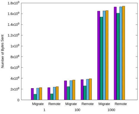
4.2 Data Propagated Size . . . 37
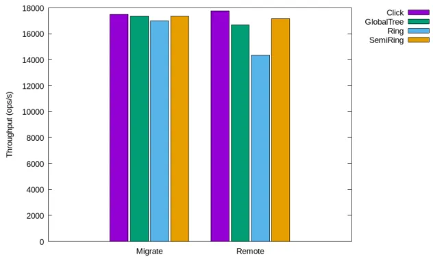
4.3 System Throughput . . . 38
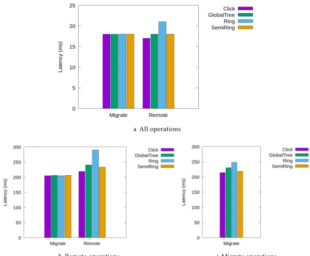
4.4 Operation latency as seen by clients . . . 39
5.1 A read operation withLOCAL_QUORUM consistency - extracted from [16] . 46 5.2 A write operation withQUORUM consistency - extracted from [29] . . . 48
5.3 Performance comparison between our solution and multiple Cassandra con-figurations . . . 64
5.4 Latency comparison between our solution and multiple Cassandra configura-tions . . . 65
5.5 Performance comparison between our solution and Saturn . . . 66
5.6 Latency comparison between our solution and Saturn . . . 67
5.7 Visibility times of each datastore configuration . . . 68
I.1 Latency of each type of operation with 1800 clients and only local operations 79 I.2 Latency of each type of operation with 1800 clients and both local and remote operations . . . 80
I.3 Latency of each type of operation with 3600 clients and only local operations 80 I.4 Latency of each type of operation with 3600 clients and both local and remote operations . . . 80
I.5 Latency of each type of operation with 5400 clients and only local operations 81 I.6 Latency of each type of operation with 5400 clients and both local and remote operations . . . 81
I.7 Latency of each type of operation with 7200 clients and only local operations 81 I.8 Latency of each type of operation with 7200 clients and both local and remote operations . . . 82 I.9 Latency of each type of operation with 10800 clients and only local operations 82
I.10 Latency of each type of operation with 10800 clients and both local and remote operations . . . 83 I.11 Latency of each type of operation with 12600 clients and only local operations 83 I.12 Latency of each type of operation with 12600 clients and both local and remote
L i s t o f Ta b l e s
4.1 Latencies between simulated datacenters (ms) . . . 34 4.2 Partition distribution across datacenters for the simulation experiments . . . 34 5.1 Latencies between experimental evaluation data centers (ms) . . . 61 5.2 Partition distribution across data centers for the experimental evaluation . . 61 5.3 Raw average visibility time (ms) . . . 69
C
h
a
p
t
e
r
1
I n t r o d u c t i o n
Distributed data stores are fundamental infrastructures in most large-scale Internet ser-vices. Most of these services, specially recent ones, demand fast response times [11,24] since latency can be perceived by users and it has been demonstrated that a slight increase often results in revenue loss for the service [12,32]. In order to provide low latency to end-users, two important properties of the underlying data store need to be considered: geo-replication and consistency.
Currently, most large-scale services requiring low latency choose to geo-replicate their system. Geo-replication means having system replicas spread across multiple geographic locations, in order to have replicas close to as many users as possible, thus decreasing response times.
This technique however, can be further improved by using partial replication. In a data store supporting partial replication, each replica of the system stores only a subset of the data. By combining partial replication with geo-replication, a service is capable of replicating, in each geographic location, only the data relevant to the users of that location. This is particularly useful for services such as social networks in which the data accessed by users is heavily dependent on their location. Another advantage of using partial replication is the lower resource requirements needed for each replica: while a replica that stores the entire dataset needs an high amount of resources (these replicas are usually materialized in data centers), a partial replica only needs resources proportional to the set of data they replicate. This means that a system using partial replication can use smaller devices as system replicas, for instance set-top boxes, user devices (such as laptops of desktop computers), or even the upcoming 5G network towers. [15,17,35].
The other important property of data stores is their consistency model. Consistency models can generally be divided in two types: strong consistency and weak consistency. Strong consistency models are usually used in applications where data consistency is
more important than latency, such as the requirements of applications using traditional (ACID) databases. In services where user-experience is a key factor, weak consistency is the preferred option as these consistency models favor system availability over data consistency.
Being the strongest consistency model that does not compromise availability [3,28], causal consistency is one of the most attractive weak consistency models, having been implemented in many recent systems [2, 7,13,26,27]. Causal consistency offers some guarantees which are more intuitive for programmers to reason about their applications (when compared to other weak consistency models such as eventual consistency) while enabling high performance and low latency (when compared to strong consistency mod-els).
1.1
Motivation
While many recent systems have implemented causal replication models, they do so us-ing different techniques which result in each implementation havus-ing a different behavior. When comparing these behaviors, the main trade-off that can be observed is between data freshness (how long an update takes to be seen by users connected to each replica) and throughput [6,20]. This trade-off is caused by the way these systems track causality, with some systems trying to reduce the amount of metadata used, which sacrifices data freshness, while others use more metadata, sacrificing throughput (and potentially la-tency) since more processing time is required to handle that metadata. The data freshness sacrifice is caused by false dependencies as a result of systems compressing metadata. As such, there is not yet a single best way to track (and enforce) causality.
Another challenge that has not yet been solved by modern systems providing causal consistency is partial geo-replication. While there are indeed causally consistent systems supporting partial geo-replication, they do so inefficiently, not taking full advantage of it.
Due to the difficulty of tracking operation dependencies when those dependencies are over objects not replicated in the local replica, these systems require partial replicas to handle metadata associated with items that they do not replicate [4,26,36]. This means not only that the metadata overhead will be higher than strictly necessary, but also that data freshness will be sacrificed, as false dependencies are introduced.
Yet another challenge with large-scale replicated systems is scalability. While sup-porting a small number of replicas can be simple, increasing the number of replicas can introduce overheads that hamper the system’s scalability. Such overheads can occur in systems where, for example, the size of metadata is proportional to the number of replicas or where a replica with some sort of central role in the system becomes a bottleneck.
1 . 2 . P R O B L E M S TAT E M E N T
1.2
Problem Statement
The primary goal of this work is explore new designs for replication protocols capable of offering causal consistency. In order to achieve this, we aim at create a solution that can better balance the trade-off between data freshness and throughput (while attempting to maximize both), with support for efficient partial replication and capable of scaling as much as possible without harming the overall system performance.
1.3
Contributions
The main contributions presented in this thesis are the following:
• Simulation work, which consisted in creating a simulator capable of testing differ-ent data propagation schemes and the subsequdiffer-ent evaluation of several possible algorithms, in order to find an appropriate one that satisfies the goals of this work. • A novel protocol for metadata propagation, which guarantees causal consistency between datacenters, while also supporting partial replication in a geo-replicated setting. This algorithm attempts to maximize throughput and data freshness while using very little metadata. Furthermore, it is able to scale with the number of servers materializing the data storage system in each data center.
• A concrete implementation of this algorithm over an existing eventual consistent datastore (Apache Cassandra [24]) and subsequent study of the effects and chal-lenges of enriching an existing data store with causal consistency.
1.4
Document organization
The remainder of this document is organized in the following manner:
Chapter2 studies related work: in particular this chapter covers the principles and techniques used for data replication; existing consistency models and their charac-teristics (with a focus on causal consistency); and the most relevant existing systems and which techniques they use to maintain different consistency models.
Chapter3 discusses the system model assumed for this work, followed by the description of the algorithms proposed, and the reasoning for such proposals.
Chapter4 describes the simulation work done for studying and validate the algorithms described in Chapter3.
Chapter5 shows the implementation of the chosen algorithm and its integration in Apache Cassandra. It also evaluates this implementation and compares it with the base system.
C
h
a
p
t
e
r
2
R e l a t e d Wo r k
In this chapter we discuss relevant related work considering the goals of the work con-ducted in this thesis. In particular we focus on the following topics:
In Section2.1the various techniques required to implement replication protocols are discussed, we discuss some of the choices that need to be considered for every replication system.
In Section 2.2 we study and compare consistency models, with special interest on causal consistency.
In Section 2.3 causal consistency is studied in more detail. We present the most common ways that existing systems use for causality tracking across operations.
In section2.4peer-to-peer networks are discussed, since they are the base of many replicated system.
In Section 2.5we present a description of relevant existing replicated data storage systems.
2.1
Replication Protocols
Many distributed systems resort to some form of data replication. Replicating data across several replicas is crucial to ensure important properties, such as:
Availability and Fault-tolerance: If a replica (or several) becomes unavailable, due to a crash, network partition, or any other reason, the system remains available since there are other replicas that contain copies of the data to ensure that the system can keep its correct operation. This redundancy of data also makes it very unlikely that any data will ever be lost, even if multiple replicas (even an entire data center) fail at the same time.
Latency: By distributing replicas across different geographic locations (geo-replication), the overall response time of the system can be improved, for users in different (and distant) locations, enhancing user experience.
However, the price to pay for these benefits is the increased system complexity, more specifically there needs to be a protocol to ensure some kind of consistency between all the replicas, and to govern how different clients should access different copies of data in different locations.
In the following discussions, we present some architecture decisions used to charac-terize replication protocols.
2.1.1 Replica Location
Refers to the physical location of the replicas in a system, which is usually related to the geographic area covered by the system and the importance of latency for users.
Co-located Co-locating replicas consist in having a distributed system replicated on the same physical location. This is usually useful when attempting to minimize the latency between replicas, since having replicas close to each other means they can have direct and fast connection channels to each others. These systems usually serve users geographically close (for instance a web service available only inside a country), since latency could become a problem when trying to serve users globally. Geo-replicated: Geo-replicating a system implies instantiating replicas in several (usu-ally strategic(usu-ally chosen) geographic locations in order to improve the data distri-bution. Having replicas physically far from each other may increase latency when synchronizing updates between replicas, however this implies that replicas are closer to the users, thus decreasing latency in communications between the user and a replica (i.e, the service). Since these systems usually focus on user experience, this trade-off is acceptable (and often welcomed).
2.1.2 Replication Schemes
Depending on the service being provided by the system, it can make more sense to replicate all the data to every replica, or instead to only replicate a subset of data in each replica.
Full Replication: In systems that use full replication, every replica is equal having a full copy of all data in the system. Replicas will behave the same way as every other replica: every update is propagated to and applied in every single replica and users can access data from any replica.
Partial Replication: By using partial replication, distributed systems can have replicas that only contain a subset of the system’s data. Using this technique can increase the
2 . 1 . R E P L I C AT I O N P R O T O C O L S
scalability of replicated systems since updates only need to be applied to a subset of replicas, allowing replicas to handle independent parts of the workload in parallel. Partial replication is particularly useful when combined with geo-replication, this allows for the deployment of partial replicas that only replicate the data relevant to that geographic location.
Using a social network as an example, there could be a partial replica in Europe that only replicates the data relative to european users. Since european users mostly access data about other european users, that replica would considerably improve those user’s experience, while avoiding the need to deploy a full replica (which would incur in higher maintenance costs).
Genuine Partial Replication[19]: Genuine partial replication is a particular case of partial replication, where each replica only receives information (meta-data or the data itself) about data items that it replicates locally. This characteristic makes genuine partial replication systems highly scalable, since they use less bandwidth and replicas need to process less information. However, this is not easy to achieve, since it’s much easier to just propagate (meta-)data to every replica and let them decide if that data is relevant to them. Additionally, there is an extra level of complexity in this case related with the handing of more complex operations that manipulate sets of data objects that are not contained within a single replica.
Caching: A cache can be seen as a partial replica, where only read operations are allowed. Caching is often used at the client-side to allow faster response time when reading frequently accessed data and to reduce server load, but can also be used at the server-side to increase the speed for responses to frequent read operations. Caches are usually temporary and are more effective for data that is modified less frequently.
2.1.3 Update Propagation/Synchronization
The method used by a replication protocol to propagate operations is usually depen-dent on what is more important: offering the client low latency times or sacrificing fast response times in favor of showing the client a more consistent view of data.
Synchronous/Eager Synchronization: Systems implementing eager synchronization pro-tocols usually behave as if there is a single replica of the system state. When a user, connected to a particular server, executes an operation that operation is immedi-ately propagated to and executed in every other replica, and only after this step is a response sent back to the client. These systems are usually associated with stronger consistency models. Since updates are propagated immediately it’s easier to maintain a consistent state between all replicas. The cost of executing each update
synchronously means these systems lack scalability since operations take longer to execute for each replica in the system, making eager synchronization protocols too costly for large-scale applications that aim to provide fast user responses.
Asynchronous/Lazy Synchronization: In contrast to eager synchronization, lazy syn-chronization protocols focus on improving response times. When a user executes an operation, that operation is usually executed on the server immediately and an answer is sent back to the client. The operation is then propagated to the other repli-cas asynchronously. These protocols often allow for replirepli-cas to evolve to divergent states, however they eventually converge as updates are propagated from replica to replica. Lazy synchronization protocols are usually associated with weaker con-sistency models, since updates are not propagated immediately and replicas are allowed to diverge in state. These system usually scale better than eager synchro-nization systems, since the synchrosynchro-nization cost is lower. They’re also preferred for applications focusing on user experience, due to their lower response times. However, systems using lazy synchronization might have issues when attempting to ensure global invariants over the application state (for example, that a counter never goes below of above given threshold values).
2.1.4 Multimaster / Primary backup
Whether or not there exists a main replica in the system is another common characteristic of replication protocols. While some use a single replica to maintain control of the system, others utilize every replica in a similar way.
Primary-backup: Many classical approaches to replication are based on the primary-backup model, in this model there is one replica (the primary replica) that has complete control over the system, and multiple backup replicas that serve only to replicate the data. Operations are sent only to the primary replica, which executes them and then propagates them (or their results) to the backup replicas, when the primary replica fails one of the backups takes its place.
Systems implementing primary-backup strategies may allow clients to execute read operations in the backups, however the data read from these replicas may be out-dated. Implementing strong consistency in systems using this replication model is usually preferred, since it’s easy to maintain consistency if only one replica can receive operations. The primary-backup model lacks in scalability, since every op-eration is executed on a single replica, adding more replicas does not increase the overall performance of the system (in the limit, it may actually decrease it due to the need to spend additional resources of the master to maintain the additional replicas up-to-date).
Multi-master: In a multi-master model, as opposed to the primary-backup model, every replica is equal and can receive and execute every operation, being up to the client to
2 . 2 . C O N S I S T E N C Y M O D E L S
choose which replica to connect to (usually the geographically closest one). Replicas then propagate their operations in the background and resolve conflicts.
This model allows for better scalability of systems, since increasing the number of replicas can increase the overall performance of the systems. The geographic positioning of replicas can also be used to decrease latency to users, improving user experience. However, since it is hard to implement a strong consistency model in a system where every replica can execute updates without synchronizing, weaker con-sistency models are usually preferred when dealing with the multi-master model, there are however multi-master systems with strong consistency, resorting to co-ordination mechanisms, such as Paxos [25], or other coco-ordination systems such as Zookeeper [22].
2.1.5 Multi-version tracking
Some systems that resort to weak consistency models (such as causal consistency) make use of versioning. Versioning is a technique which consists in keeping several versions of the same data item at the same time. The most common uses for versioning are:
• Consistency - In order to maintain consistency in the system, sometimes older versions of data need to be returned to the client (for example when the newer version has not yet been propagated to every replica).
• Transactions - For systems that support transactions, versioning can be useful to allow users to keep operating on the adequate versions of data items that are being accessed and modified by other transactions.
In order to distinguish between data versions each version needs to have some kind of identifier, these identifiers are usually based on whichever technique the system uses for tracking causal relations (for example, a vector clock).
2.2
Consistency models
According to the original CAP theorem [9,18], it is impossible for a distributed system to provide all of the following guarantees simultaneously:
• Consistency - Showing the user only strongly consistent data
• Availability - Having the system always available to the user, even in the presence of failures
• Partition tolerance - Keeping the system functional and correct in the presence of network partitions
In the context of distributed systems (and particularly in the CAP theorem), the def-inition of consistency is different from the context of, for example, database systems. Consistency in CAP means that in a distributed system, independently of how the data is stored in servers, users should see that data as if there was only a single up-to-date copy of it.
The CAP theorem further defines that only two out of these three properties can be provided by a distributed system simultaneously however, this formula is misleading [8]. In reality, CAP only prohibits a specific situation: perfect availability and strong consistency in the presence of partitions, which are unavoidable in large scale systems such as geo-replicated systems.
With this in mind, distributed applications usually need to choose between consis-tency or availability. While it is possible for system to guarantee both consisconsis-tency and availability in the absence of such failures [8], most systems nowadays are distributed and hence subject to suffer network partitions.
While traditional database systems (with ACID guarantees) choose consistency over availability, recently most systems where user experience is essential to ensure success, as seen in the NoSQL movement for example, choose availability over strong consistency [2,11,24].
2.2.1 Strong Consistency
A system that chooses consistency over availability typically focuses on providing guar-antees in line with one of the existing strong consistency models. In these models every operation is observed by all users in the same order, meaning that users will always observe consistent states of the system. This kind of consistency is important in situa-tions where always having a consistent, up-to-date state is essential to the overall system correctness. We now discuss two of the most relevant strong consistency models:
Serializability: For a system to provide serializability, every client must see the opera-tions issued to the system in the same order, even if that order does not correspond to the global real-time order in which the operations were actually issued. In order to keep the state of every replica consistent, all replicas must appear to execute op-erations simultaneously. Without this requirement, a client could read two different values from two distinct replicas.
Linearizability: Linearizability can be seen as a particular case of serializability. In this case all replicas need to execute operations in the same order, however that order needs to be the real-time ordering in which they were issued.
For instance, considering 3 clientsC1, C2, and C3 issuing 3 operations op1, op2, and op3, respectively and in this order, considering an external unique source of time.
To provide serializability the system only needs to make sure every replica executes these operations in the same order (for instance:op2, op3, op1), however to provide
2 . 2 . C O N S I S T E N C Y M O D E L S
linearizability every replica must execute the operations in the order:op1, op2, op3
since that was the real-time ordering in which the operations were issued.
2.2.2 Weak Consistency
Weak consistency models, as opposed to strong consistency models, are typically de-ployed in scenarios where availability is chosen over consistency. In these models opera-tions may not be seen in the same order by every replica and reads issued by clients may return out-of-date values, we now discuss three consistency models that fall within this category.
Eventual Consistency Eventual consistent systems usually try to achieve high availabil-ity. As the name suggests, in this kind of systems, when there are no more updates to a certain data item, all nodes will eventually converge to the same state. This means that, before reaching the converged state, the system may be inconsistent, allowing users to see out-of-date and/or unordered values. To reach a converged state, there needs to be some sort of conflict resolution protocol, with the last-write-wins [34] approach being the most common, although the use of CRDTs [33] has gained some popularity recently [1,23].
Causal Consistency Causal consistency is one of the strongest weak consistency mod-els, being compatible with providing availability in the light of the CAP theorem. This makes causal consistency a very attractive option for systems that need high availability while trying to achieve the strongest possible consistency.
This consistency model requires the system to keep track of causal dependencies between operations and ensures that those operations are always seen by clients in an order that respects their causality relations.
Causally related operation are operations in which one might influence the other, for instance, in a social network, if a user creates a post and then immediately removes it, the remove operation is causally dependent of the create operation. Operations that do not have any relation between one another, being independent, are called concurrent operations. These operations do not have to be presented to users in any particular order because of this. Simultaneous (and therefore con-current) writes, for example, are concurrent operations: since they are concurrent, one couldn’t influence the other, since it would be impossible for any of them to be triggered by the observation of the effects of the other.
Causal+: Causal+ consistency is achieved by adding convergent conflict handling to causal consistency. Convergent conflict handling ensures that replicas even-tually converge, by making them all deal with conflicts in the same way. This property ensures that clients will eventually observe the same (converged) state, if there are no more write operations being performed over the system.
2.2.2.1 Differences between eventual and causal consistency S1 S2 S3 C1 C2 x:0 x:0 x:0 W(x,1) x:1 x:1 R(x) 0 R(x) R(x) 0 1 Sync time a Example 1 S1 S3 C1 C2 x:0 x:0 W(x,1) x:1 x:0 y:2 R(x) 0 2 R(y) Sync W(y,2) y:2 y:0 y:0 y:0 x:1 x:1 Sync S2 x:0y:0 time y:2 b Example 2 S1 S3 C1 C2 x:0 x:0 W(x,1) x:1 x:0 y:2 R(x) 0 2 R(y) Sync W(y,2) y:2 y:0 y:0 y:0 x:1 x:1 y:2 Sync S2x:0 y:0 C3 R(x) 1 x:1 y:0 Sync time c Example 3
Figure 2.1: Execution examples that are allowed by eventual consistency but not by causal consistency
In this section, we present examples on the differences between eventual and causal consistency, using Figure2.1 as reference. In this figure, c1, c2 and c3 refer to clients
operating in a system consisting on three replicas:s1, s2, s3. x and y represent the keys of
objects stored in these replicas. These keys are accessed using read and write operations. These operations are represented by arrows labeled with either andR or W, where the
parameter in a read operation is the key to access and the parameters in a read operation are the key and the new value.
Figure2.1ashows an example of a situation allowed by eventual consistency but not by causal consistency. In this example,c1 first reads the initial value of x followed by a
read to the updated value ofx and finishing with re-reading the initial value.
In Figure2.1b, two write operation are issued byc2. Since the write operations are
issued by the same client, they are considered causally dependent. As they are causally dependent,c1 should not be able to see the effects of the second one without seeing the
effects of the first. As such, this execution is valid under eventual consistency but not under causal consistency.
2 . 3 . T R AC K I N G C AU S A L I T Y
of the operation issued by c3 without seeing the effects of the operation issued by c2.
However, in this case, the causal dependency originates fromc3 reading the effects of the
first operation and then issuing a write operation.
2.3
Tracking Causality
Being one of the strongest consistency models for systems that focus on availability, the causal consistency model is a very attractive consistency model. Simply assigning a global order to each operation (using Lamport timestamps, for example) is enough to guarantee causality. However, this is not an efficient method, since concurrent operations will still be ordered without need. A more efficient method to guarantee causality is by tracking causal relations between operations, and then applying those operations in an order that respects these causal relations. This means that only dependent operations will be ordered, while concurrent operations can be executed in any order. Since there is no single best way to track causality, the performance of causally consistent systems is usually dependent on which protocol or technique is used. The basic concept, in which most causality tracking techniques are based, is the concept of causal history.
2.3.1 Causal history
Figure 2.2: An example causal history - Adapted from [5]
Throughout this section we follow the definitions originally presented in [5]. Using causal histories is a very simple way of tracking causality. The causal history of an event can be defined as the set of events that happened before that event. Imagine a system with 3 nodes (A, B, and C) in which, every time an events occurs in a node, that node assigns the event a unique identifier composed by the node name and a local increasing counter. Each event’s causal history is composed of its identifier and the causal history of the previous event that occurred at that node.
For example, as seen in Figure2.2, the second event in nodeC has the name c2 and
the causal history Hc2={c1,c2}. Also, when a message is propagated to another node,
is received, the remote causal history is merged with the local one. This can be seen in Figure2.2when node B receives a message from node A, both causal histories are merged, and a new event b2 is created.
In a system with this behavior, checking for causality is now simple: if an event identifier is contained in another event’s causal history, that means the second event is causally dependent on the first; if neither event identifier is contained in the other causal history, then the events are concurrent.
While causal histories do work, the algorithm described above is not easy to imple-ment in an efficient way, as the size of meta-data in a real system impleimple-mentation would grow infinitely. Several techniques have been created to address this challenge, by using the concept of causal history but in more efficient manners:
Vector clock: By studying the structure of causal histories, there’s an important charac-teristic that can be observed: if a causal history includes an event B3, then it also includes all events from nodeB that precede b3 (b2 and b1). Given this property,
the preceding events do not need to be stored, and only the most recent event from each node is stored.
With this in mind we can, for example, compact the causal history {a1, a2, b1, b2, b3, c1, c2, c3} into the representation {a 7→ 2, b 7→ 3, c 7→ 3} or simply a vector [2, 3,
3]. This vector is called a vector clock.
All the operations performed over a causal history have a corresponding operation identified by a particular vector clock:
• When a new event occurs in a node, instead of creating a new identifier for the event and adding it to the causal history, it’s only needed to increase the number corresponding to that node in the vector clock. For instance, after an event occurs in nodeB, the vector clock [1, 2, 3] becomes [1, 3, 3].
• The union of causal histories (when nodes send messages to other nodes), is equivalent to choosing the max value from each position of each vector and placing it in the new vector. For example, the union of the vector clocks [1, 2, 3] and [3, 2, 1] results in the vector clock [3, 2, 3]. Using a more formal explanations, for two vectors Vxand Vy, the result Vzof their union is achieved
the following way: ∀i : Vz[i] = max(Vx[i], Vy[i])
• To check if there’s a causal dependency between two events, checking if every position of the vector identifying an event is greater or equal to the correspond-ing position in the other event vector, and vice versa is enough. Vector Vx is
causally dependent on vector Vyif: ∀i : Vx[i] ≤ Vy[i] and ∃j : Vx[j] < Vy[j]. Usually, in storage systems, only state changes need to be tracked. As such, a new event identifier only needs to be generated when a write operation occurs (since read operations do not change data). This is called a version vector.
2 . 4 . P E E R -T O - P E E R
Nearest dependencies: Another property that can be observed in causal histories is that an event’s causal history contains the causal history of all the events it causally depends on. Going back to Figure2.2, the causal history ofb2 includes both a1 and a2, however, since the causal history of a2 already contains a1, there’s no need to
storea1 in the causal history of b2.
This concept is used, for example, by COPS [26]: by only storing the closest depen-dencies in the causal history of an event it is still possible to transitively rebuild the full causal history of an event.
2.3.2 Metadata Propagation
A different way to guarantee causality is to control the propagation of metadata to ensure updates are executed on remote replicas in a causally consistent fashion. Saturn [7] works by exploiting this observation: it separates data and metadata management, and uses a decentralized metadata manager that delivers the metadata to data centers in a causal order. In order to do this, Saturn organizes every datacenter into a single static tree, in which metadata is propagated through its branches in a FIFO order. Data centers then apply the updates only when they receive the metadata handled by the metadata manager, which guarantees the updates are executed in causal order, even if the data itself is received in a different order.
2.4
Peer-to-Peer
A peer-to-peer system is a decentralized system in which there is no single central server, each peer implements both server and client functionalities. By allocating tasks among peers, bandwidth, computation, and storage are distributed across all participants[31].
For a new node to join the system, there is usually little manual configuration needed. Nodes generally belong to independent individuals who join the system voluntarily, and are not controlled by a single organization.
One of the biggest advantages of peer-to-peer is its organic growth: due to the dis-tribution of tasks, each node that joins increases the available resources in the system, meaning the system can grow almost infinitely.
Another strength of peer-to-peer is its resilience to attacks and failures: since there is usually no single point of failure, it is much harder to attack a peer-to-peer system than it is to attack a client-server system. The heterogeneity of peers also makes the system more resilient to failures since a failure that affects a portion of nodes usually does not affect every node.
Popular peer-to-peer applications include file-sharing, media streaming and volunteer computing.
For a peer-to-peer system to function properly, nodes need to be aware of the under-laying network and its topology. To facilitate communications between nodes, creating
a logical network that only includes the nodes that belong to the system is the most common approach. This logical network is called an overlay network.
2.4.1 Overlay Networks
An overlay network is a logical network, built on top of another network. In an overlay network, nodes are connected by virtual links, which connect two nodes directly through a combination of multiple underlying physical links. In peer-to-peer systems, this un-derlying network is usually the Internet. The overall efficiency of a peer-to-peer system is dependent on its overlay network, which should have the adequate characteristics to serve that system.
The fundamental choices in an overlay network are the degree of centralization (decen-tralized vs partially cen(decen-tralized) and the network topology (structured vs unstructured). Degree of centralization: Overlay networks can be classified by their use of centralized
components (or the lack of).
Partially centralized: These networks use dedicated nodes or a central server to have some kind of control over the network, usually indexing the available nodes. These nodes are then used as coordinators, facilitating the entrance of new nodes into the system and coordinating the connection between nodes. Partially centralized systems are easier to build than decentralized systems, however they come with some of the drawbacks of client-server architectures such as a single point of failure and bottleneck. This bottleneck may also negate the organic growth that characterizes these systems.
Decentralized: In this design, the use of dedicated nodes is avoided, making ev-ery node equal. This way bottlenecks and single points of failure are avoided, while the potential for scalability and resilience is higher when compared to partially centralized systems. However, since there is no coordinator node, these network have to rely on flooding protocols to propagate queries/changes, which is less efficient than having a coordinator node. These systems some-times "promote"nodes to supernodes, these nodes have increased responsibil-ities are often chosen for having a significative amount of resources. While supernodes may increase system performance (for instance, by helping new nodes enter the system), they may bring some of the drawbacks of partially centralized networks.
Structured vs unstructured: Choosing between structured or unstructured architectures usually depends on the amount of churn1the system is expecting to be exposed to and the potential usefulness of key-based routing algorithms to the applications being supported by the overlay network.
2 . 5 . E X I S T I N G S Y S T E M S
Structured overlays: In this kind of overlay network, each node is usually assigned an unique identifier in the range of numerical values that determines the node’s position in the network. Identifiers should be chosen at random and the nodes should be distributed in an uniform fashion across the identifier space. This results in the nodes being organized in a structured way, usually named DHT (Distributed Hash Table). This structure works similarly to an hash table: each node is responsible for a set of keys and can easily find the node responsible for any key. Structuring the nodes in a DHT allows for the use of key-based routing algorithms, increasing the efficiency of queries, however, it sacrifices performance when churn is high since the DHT must be updated for each node that enters or leaves the system, which is a process that has non-negligible overhead while also requiring the coordination of multiple nodes.
Unstructured overlays: In unstructured overlays, there is no particular structure linking the nodes, which means that queries are usually propagated by flood-ing the network. The overlay is formed by establishflood-ing arbitrary links between nodes, meaning peers only have a partial view of the network (usually they only know themselves and a few neighbors). In unstructured overlays we have the opposite of structured overlays: queries are less efficient since they need to be propagated to every node to make sure they reach the ones owning relevant content, however this architecture handles churn much better than structured overlays. Since the management of the topology is much more relaxed (i.e has few restrictions).
2.5
Existing systems
In this section, we present the most relevant existing causal consistent systems and give a brief overview on how they track causality.
The following systems are not explained in detail as they do not provide partial repli-cation, which is a key characteristic in the solution we aim at devising. However, they are historically important when considering causal consistency, and they introduced ideas which we leveraged in our work.
COPS[26] was the first system to introduce the concept of causal+ consistency, the strongest consistency model under availability constraints. COPS also contributed with its scalability, being able to track causal dependencies across an entire cluster. It works by checking, for each operation, if its causal dependencies have already been satisfied before making its results visible. It uses client-side metadata to keep track of the dependencies for each client operation.
Eiger[27] is a scalable, geo-replicated storage system that innovates, in relation to COPS, by supporting causal+ consistency using column family data models (popularized
by Cassandra [24]), while most systems support only key-value data models. It also supports both read-only and write-only transactions, even for keys spread across multiple servers.
ChainReaction[2] is a geo-distributed key-value datastore. It uses a variant of the chain-replication technique that provides causal+ consistency using minimal metadata. By using this special variant of chain-replication, ChainReaction is able to leverage the existence of multiple replicas to distribute the load of read requests in a single data center. It also leverages a more compact metadata management scheme, used to enforce causal consistency.
GentleRain[13] is a causally consistent geo-replicated data store. It uses a periodic aggregation protocol to determine whether updates can be made visible or not. It differ from other implementations by not using explicit dependency check messages. It uses scalar timestamps from physical clocks and only keeps a single scalar to track causality which leads to a reduced storage cost and communication overhead, however updates visibility may be delayed.
Kronos[14] is a centralized service, with the purpose of tracking dependencies and pro-viding time ordering to distributed applications. It provides an interface by which applications can create events, establish relationships between events, and query for pre-existing relationships. Internally, in order to keep track of dependencies, Kronos maintains an event dependency graph.
The following systems are explained in more detail as they are the more recent and the closest ones to the solution we wish to implement.
Saturn[7]: Saturn was designed as a metadata service for existing geo-replicated systems. Its purpose is to provide causal consistency to systems that do not yet ensure it by design, in an efficient way. It does this by controlling the propagation of metadata for each update, making sure that it is delivered to data centers in an order that re-spects causality. For this to work, servers can only apply each update after receiving the corresponding metadata from Saturn, even if that means having to wait after receiving the update data. Saturn also enables genuine partial replication, which ensures its scalability. Internally, Saturn organizes data centers in a tree topology (with data centers as leaves), connecting the tree with FIFO channels. Causality is guaranteed by making sure metadata is propagated in order (using the mentioned channels).
Being a novel approach to causality tracking, we are interested and will use in this work some aspects of Saturn, such as its separation between data and metadata and the handling of metadata by a separate service. We also leverage on the idea of using FIFO channels to guarantee causal consistency.
2 . 5 . E X I S T I N G S Y S T E M S
With this said, Saturn still has some weaknesses that we wish to avoid: organizing the metadata propagation layer in a static tree means that supporting dynamic entry and exit of datacenters in the system is very difficult; using a tree also means that the nodes closer to the root are likely to experience higher load than the nodes closer to the leaves; the lack of any kind of dependency metadata (for instance a vector clock) results in false dependencies.
In addition to these, Saturn shows what we think to be its main fault when we reason about how it could be integrated in a weakly consistent data store: In each datacenter, the order in which remote operations are executed must be the same as the order in which the metadata for these operations was received from the tree structure. This happens because, since there is no dependency information, opera-tions cannot be executed concurrently. In practice, this means that each datacenter can only execute a very small number of remote operations at a time, resulting in very high visibility times and the inability to scale with the number of nodes in a datacenter.
Eunomia[21] is a recent work that provides causal consistency guarantees in a fully replicated geo-distributed scenario. It expands the proposal of Saturn [7] of decou-pling the data replication layer from the causality tracking layer. Eunomia allows local client operations to always progress without blocking by relying on a intra-dc stabilization technique. This technique relies on a hybrid physical-logical clock per data partition that is associated with each client operation. Based on these clocks, the Eunomia service gathers progress indicators (either operations or notifications that no operation occurred) from each local data center partition, establishing a total order of operations that is compatible with causality per data center. This total order is then employed by the Eunomia service to execute remote operations on each data center.
Due to the use of a total order, Eunomia can propagate minimal metadata across data centers. However data centers are limited to the execution of one single re-mote operation per rere-mote data center simultaneously. The use of the local data center stabilization procedure can delay the propagation of operations to remote data centers significantly and hence, affect negatively the global visibility times of operations. Furthermore, and contrary to Saturn, Eunomia cannot support partial replication.
We also present Cassandra that, while not providing causal consistency, will still be used in this work as the base datastore system.
Cassandra[24]: Cassandra is a highly scalable and available, decentralized NoSQL database. It offers eventual consistency of data and allows for some tuning of consistency. For this work we are mostly interested in how Cassandra handles data distribution
and replication, and will ignore inner workings like how the data is stored on disk, indexed, or how clients interact with it.
First, we need to explain some key terms and concepts of Cassandra, which will later be referenced in the document (mostly in Chapter5):
Node: Represents the basic component of Cassandra, where the data is stored. Usu-ally each node represents a single physical/virtual machine.
Datacenter: Represents a collection of related nodes, which may or may not be part of an actual physical datacenter, but should always be physically close. Cluster: Contains one or more datacenters. Represent an entire instance of the
database.
Keyspace or partition is a namespace (or a container) for a subset of data that is usually used to differentiate data according to its role in the application. For instance, there is a default “system” keyspace that is used to store information about the database details and configuration. Keyspaces are essential in sup-porting partial and geo-replication since each can have a different replication strategy.
Replication Factor: Is the number of nodes of each datacenter that replicate each row of data.
Replication Strategy: Each keyspace must have a replication strategy assigned. A replication strategy specifies in which datacenters the data will be replicated, and the replication factor in each of these datacenters. For instance, the fol-lowing command creates a keyspace named “users” with a replication factor of 3 in the datacenter “europe” and a replication factor of 2 in the datacenter “canada”.
1 CREATE KEYSPACE users WITH replication = { 2 ’ class ’: ’ NetworkTopologyStrategy ’, 3 ’ europe ’:3 ,
4 ’ canada ’:2
5 };
Each row inserted in this keyspace will now be stored in 3 nodes of the “europe” datacenter plus 2 nodes of the datacenter “canada”, these nodes can be any subset of nodes on these datacenters.
Virtual nodes or vnodes: are used to distribute rows across nodes in a datacenter. Each node is assigned a number of vnodes which influences the amount of data that node will be responsible for. This is useful if nodes don’t all have the same processing power or, in our case, some nodes are running extra tasks.
Cassandra nodes use Gossip, a peer-to-peer communication protocol to exchange information about themselves and other known nodes. By periodically exchanging
2 . 5 . E X I S T I N G S Y S T E M S
state messages, every node quickly learns about all other nodes in the cluster. This information is used for nodes to know which other nodes are interested in each operation (i.e, which nodes store each data object).
Inside each datacenter, nodes are organized in a DHT (as explained in Section2.4), which is used in conjunction with the replication factor and vnodes to determine which nodes are responsible for each row of data.
By using different keyspaces with different replication strategies, we can easily setup a partially replicated cluster with geo-replication. We chose Cassandra as the base system for this work both because of this and because of its popularity and well-maintained open source code.
While Cassandra already implements most of the characteristics we desire for this work, it is important to emphasize that is does so while only guaranteeing eventual consistency.
Summary
In this Chapter, we presented all the relevant related work that was studied and used and as basis for this thesis.
In the following Chapter, we will present the system model assumed for this work, followed by the design decisions that were done in order to reach the first iteration of our solution. We also present an algorithm capable of assuring the guarantees we’re looking for and explain how it works.
C
h
a
p
t
e
r
3
A l g o r i t h m s f o r c au s a l c o n s i s t e n c y
In this chapter we introduce and discuss some algorithm designs that were initially considered as possible solutions for providing causal consistency in partially replicated databases. The protocol must be scalable with the number of nodes in the system. We are also interested in minimizing the effects of churn and maximizing throughput and data freshness.
We start by presenting the system model assumed for this work. In our design, we separate the system in two layers, the datastore layer and the causality layer. We then present some intuitions about the characteristics of possible algorithms. We finish by presenting and explaining an algorithm capable of ensuring the consistency guarantees that we are looking for.
3.1
System Model
The focus of this thesis is on enforcing causal consistency guarantees under partial repli-cation. We aim at providing such guarantees in the most independent way possible of the concrete datastore. Due to this, we start by defining the minimal set of assumptions that we made regarding the operation of the underlying data storage system.
Storage System Consistency: We assume that the storage system provides eventual con-sistency across data centers, allowing an update to be executed in a data center with-out coordinating with other data centers. Updates are propagated asynchronously to other data centers.
Within a data center, we assume that after a write completes, all following reads will return the written value. While a write of an object is in progress, the value returned by a read can be either the old or the new value. Unlike linearizability, it is possible that after a read returns the new value, some other read (issued by other
client) may still return the old value. This is the common behavior of replication systems based in quorums that return the most recently written value (and not the value of the majority). However, we assume that this cannot happen to a single client (i.e., a client cannot read a value and then read an older value). This can be enforced in two ways: by having client caching values returned by read operations; or by simply having clients always contacting the same quorum of nodes when reading a given object.
Partial and Geo-replication: We also assume the underlying datastore already supports (some form of) partial and geo-replication. This means that each datacenter should know which datacenters replicate each data object as to be aware of the datacenters where to propagate updates to that particular data objects.
FIFO channels and variable latency: For now, we assume that it is possible to establish connections between datacenters that produce FIFO (first-in first-out) delivery. This means that messages sent from one datacenter to another are delivered in the same order they were sent. This assumption may not be needed for all algorithms. We also consider the possibility of failures or delays on the communication channels which can lead to variable latency in the delivery of messages between datacenters. Sharding: Even though we are thinking of datacenters as unique nodes, we’re still going
to assume they implement some form of sharding. Sharding is a technique that consists in splitting the data that a datacenter is responsible for and storing each piece in a different node of that datacenter. With sharding, a datastore is able to spread the load evenly between all its nodes. For instance, if we execute 100 write operations in a datacenter with 10 nodes, each node will (on average) only need to execute 10 operations, whereas in a datacenter without sharding, a single node would have to execute all 100 operations. This implies that the datastore system can be scaled horizontally within a datacenter.
3.2
Design Considerations
With the specified system model, we now present some intuitions about the principles and techniques we considered in order to design the proposed algorithm.
3.2.1 Layer Separation
As a starting point, we depart from some of the insights introduced by the Saturn[7] system. As Saturn, we decided to separate the system in two layers: the datastore layer and the causality layer. The general principle behind this idea is the following: when the datastore layer receives a write operation from a client, it executes the operation locally and propagates it to the other datacenters that are interested in the operation (i.e, that replicate the data object modified by the client request). Additionally, a label that
3 . 2 . D E S I G N C O N S I D E R AT I O N S
represents that operation is also sent to the causality layer. When a datacenter receives an operation from another datacenter, it must wait for the reception of the corresponding label from the causality layer before it can execute the operation.
This separation in layers brings some advantages:
• By using this separation of layers, guaranteeing causality in the system becomes simpler, since we can focus only on the design and properties of the causality layer. By delivering operation labels to the datastore layer in causal order, we achieve causal consistency in the system.
• The (possibly large) operation itself is sent directly to the relevant datacenters in the datastore layer, while the causality layer will only process and propagate smaller labels, which can be relevant to minimize communication overhead at the causality layer.
• This separation will also be useful when implementing the resulting protocol over an existing datastore, since the changes to the datastore code will be minimal. We only need to change the behavior of the datastore in very specific locations (gen-erating a label to send to the causality layer, waiting for the label to execute the operation, and acknowledging executions back to the causality layer).
With this decision made, we moved on to the next stage: how to efficiently organize the causality layer while supporting partial replication, maximizing throughput, minimizing data visibility times, and allowing the presence of dynamic datacenters.
3.2.2 Causality Layer Structure
We started by deciding how the causality layer should be organized. Saturn organizes all datacenters in a single tree topology. Having all datacenters organized in this fashion means we would not need to use any extra metadata (like vector clocks or explicit de-pendencies) to track causality, we would simply need to send all labels through the tree (assuming FIFO channels).
Instead of having the datacenters organized in a single tree structure, we can also propagate labels using different (and independent) trees depending for example, on the datacenter where the operation originated. This translates in having one tree per data-center in the system, where each datadata-center is the root of its own tree. These trees could then be optimized depending on the distribution of data in the system (i.e, the partial replication scheme employed), in order to better distribute the load in the causality layer. Having multiple trees, however, would mean that sending labels in a FIFO channel is no longer enough to guarantee causality, since causality is only guaranteed between op-erations propagated through the same tree. As such, in each label, we need to append a vector clock. Since each tree by itself guarantees causality between operations that transverse it, this clock effectively tracks dependencies between trees, which means the
size of the clock depends on the number of trees (i.e, the number of datacenters). While this addition of a vector clock to each label will increase the load on the causality layer, some metadata will always be required, as we will explain further below in this section.
A particular case of this multiple tree layout would be having trees where the root connects to every other (relevant) node, which would result in every label being sent directly to every interested datacenter. In this case, supporting high churn is trivial, since we don’t need to change anything in the layout of the causality layer when a datacenter enters or leaves the system. On the other hand, with either single or multiple trees, a datacenter joining or leaving requires the trees topology to be reconfigured, which would require that a part of (or even the entire) system stops executing operations while this reconfiguration takes place.
3.2.3 Concurrency and False Dependencies
Having the causality layer organized in a single tree may seem like a good idea at first, since, as explained before, the tree by itself guarantees causality. The most significative issue with this approach is the lack of concurrency in the execution of remote operations. Since datacenters are receiving each label in a specific order, without any information about their dependencies, they have to assume that every label is causally dependent of all labels previously received, which means all operations must be executed one by one in the order they were received. This effect is called “false dependencies” and, as explained in Section1.1, it is usually mitigated by attaching more precise dependency information to each label. Since we are considering that the datastore layer supports sharding, having no concurrency in the execution of remote operations becomes even more penalizing, since the advantages of sharding is lost (for remote operations). As a result of these observations, we conclude that labels must have some dependency information attached to them and, as such, it makes more sense to rely on multiple trees over a single tree.
3.2.4 Vector Clock vs Explicit Dependencies
After having decided that we will be using multiple trees and that we need dependency information in labels in order to support concurrent execution of operations, making it possible to take advantage of sharding in the datastore layer, we’re left with another decision: how fine-grained should that dependency information be.
Here we consider two options: maintaining a vector clock with one entry per datacen-ter and attach it to the labels or, using a more complex option, having the clients keep track of direct dependencies explicitly and attaching them to every operation.
By only using a vector clock, the effect of false dependencies is more visible, when compared to using explicit dependencies. However, this solution has the advantages of adding very little extra metadata to labels, which is important in order to keep the causality layer from being a bottleneck to the system, while also respecting the separa-tion between layers, by avoiding to require the storage of explicit dependencies in the
![Figure 2.2: An example causal history - Adapted from [5]](https://thumb-eu.123doks.com/thumbv2/123dok_br/15472667.1034855/29.892.226.673.660.842/figure-example-causal-history-adapted.webp)
![Figure 5.1: A read operation with LOCAL_QUORUM consistency - extracted from [16]](https://thumb-eu.123doks.com/thumbv2/123dok_br/15472667.1034855/62.892.260.626.171.689/figure-read-operation-local-quorum-consistency-extracted.webp)
![Figure 5.2: A write operation with QUORUM consistency - extracted from [29]](https://thumb-eu.123doks.com/thumbv2/123dok_br/15472667.1034855/64.892.260.646.346.867/figure-write-operation-quorum-consistency-extracted.webp)