www.nat-hazards-earth-syst-sci.net/12/3441/2012/ doi:10.5194/nhess-12-3441-2012
© Author(s) 2012. CC Attribution 3.0 License.
and Earth
System Sciences
Seismic vulnerability of the Himalayan half-dressed rubble stone
masonry structures, experimental and analytical studies
N. Ahmad1,2, Q. Ali2, M. Ashraf3, B. Alam3, and A. Naeem3
1ROSE School-IUSS Pavia, Pavia, Italy
2Earthquake Engineering Center, University of Engineering & Technology (UET), Peshawar, Pakistan 3Civil Engineering Department, University of Engineering & Technology (UET), Peshawar, Pakistan
Correspondence to:N. Ahmad ([email protected])
Received: 27 April 2012 – Revised: 10 July 2012 – Accepted: 9 October 2012 – Published: 21 November 2012
Abstract. Half-Dressed rubble stone (DS) masonry struc-tures as found in the Himalayan region are investigated us-ing experimental and analytical studies. The experimental study included a shake table test on a one-third scaled struc-tural model, a representative of DS masonry structure em-ployed for public critical facilities, e.g. school buildings, offices, health care units, etc. The aim of the experimen-tal study was to understand the damage mechanism of the model, develop damage scale towards deformation-based as-sessment and retrieve the lateral force-deformation response of the model besides its elastic dynamic properties, i.e. fun-damental vibration period and elastic damping. The ana-lytical study included fragility analysis of building proto-types using a fully probabilistic nonlinear dynamic method. The prototypes are designed as SDOF systems assigned with lateral, force-deformation constitutive law (obtained ex-perimentally). Uncertainties in the constitutive law, i.e. lat-eral stiffness, strength and deformation limits, are consid-ered through random Monte Carlo simulation. Fifty proto-type buildings are analyzed using a suite of ten natural ac-celerograms and an incremental dynamic analysis technique. Fragility and vulnerability functions are derived for the dam-ageability assessment of structures, economic loss and casu-alty estimation during an earthquake given the ground shak-ing intensity, essential within the context of risk assessment of existing stock aiming towards risk mitigation and disaster risk reduction.
1 Introduction
Mountainous regions in the Himalayan largely employ stone masonry in building constructions, either as load-bearing walls or as an infill in timber framing structures. For exam-ple, in Pakistan stone masonry is used in construction in 40 to 80 percent of sub-administrative units (Tehsil) of the state of Khyber Pakhtoonkhwa and Punjab (Maqsood and Schwarz, 2008). This is due to the fact that stone material is abundantly available in northern parts of Pakistan. Low-cost and low-skilled labour may be employed for construction work that consequently results in overall economical schemes.
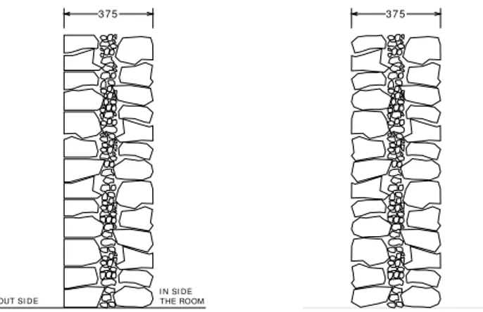
Stone masonry buildings in the Himalayan region consist of two-wythe, load-bearing walls (Fig. 1). The void between the wythes is left empty or filled with small stones. For ru-ral constructions, i.e. residential buildings, bearing walls are built in rubble stone masonry in which undressed stone units are laid randomly in mud mortar or simply placed in dry form, whereas half-dressed stone units laid in cement mortar are employed for urban constructions, i.e. public buildings. The buildings are provided with wooden floors in case of ru-ral constructions, whereas reinforced concrete slab floors and roofs are used in the case of urban constructions (Ali and Mo-hammad, 2006; Gupta et al., 2008). The public buildings are also provided with a lightly reinforced roof band (ring beam) at the top of the walls.
3 75
OUT SI DE
I N SI D THE R E OOM
37 5
Figure 1 Cross-section of the typical stone masonry
Fig. 1. Cross-section of the typical stone masonry load-bearing walls practiced in the Himalayan region.From left to right: half-dressed coursed masonry wall employed for public buildings (in-vestigated in the present study) and undressed random masonry wall employed for rural residential buildings.and past earthquakes (e.g., Ali and Mohammad, 2006; Both-ara and Brzev, 2011; Gupta et al., 2008; Kaushik et al., 2006; Murty, 2003; Naseer et al., 2010; Rai and Murthy, 2006,). The poor performance of stone masonry buildings have also been observed in other parts of the world (Adanur, 2010; Akkar et al., 2011; Gulkan et al., 1992; Ingham and Griffith, 2011; Spence, 2007a).
Earthquakes observations may provide significant qualita-tive information on the earthquake resistance and vulnera-bility of stone masonry buildings common in the Himalayan region. However, there is very limited quantitative informa-tion available to help derive analytical fragility and vulnera-bility functions for half-dressed stone DS masonry in urban structures found in the Himalayan region. It is very essential to investigate this construction type, as most of the public buildings that represent critical facilities like school build-ings, offices, health care units, etc., are constructed of load-bearing walls built in half-dressed stone masonry in cement mortar and are provided with reinforced concrete slab floors and roofing. In the recent 2005 Kashmir earthquake, about 19 000 children unfortunately died because of the collapse of school buildings of the mentioned characteristics (EERI, 2006). The current state of geodynamic settings in the region has shown to be capable of triggering further future large earthquakes up to or even greater than a magnitude 8 (Avouac et al., 2006; Bilham, 2004), which makes it essential to as-sess, communicate and consequently mitigate the risk of the existing vulnerable stock.
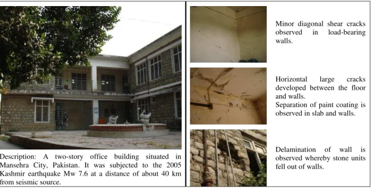
Figure 2 reports an office building in Mansehra City of Pakistan that was moderately damaged in the 2005 Kash-mirMw=7.6 earthquake. Typical damages observed in the
building are also described. This city was reported with an intensity of VII–VIII on the MMI scale (Javed et al., 2008). Similar types of dressed stone DS masonry buildings found
in the Governor’s estate in Darjeeling were damaged during the recent 2011 Sikkim earthquake in India. Typical damages observed in Darjeeling public buildings included separation at wall junctions and in-plane shear failure (EERI, 2012). The complex seismic behavior of this construction type ren-ders its modeling timid for analytical studies. Thus, exper-imental investigations are essential to calibrate engineering tools and help develop simplified hypotheses for seismic analysis and vulnerability assessment of the considered con-struction type.
This study presents research carried out on the seismic assessment of DS masonry structures employed for public buildings (schools, offices, health care units, etc.). It is part of the research program focusing on the seismic vulnerabil-ity assessment of typical building types in the Himalayan re-gion aiming towards risk mitigation and disaster risk reduc-tion in the region (Ali et al., 2012). Fragility and vulnerabil-ity functions are derived herein by means of analytical and experimental investigations. The present study provides es-sential input for risk assessment of the considered DS ma-sonry structures aiming towards risk mitigation (pre-event phase) and disaster risk reduction (post-event phase) in the Himalayan region in general and northern Pakistan in partic-ular.
2 Experimental investigation of half-dressed stone masonry model by means of dynamic shake table test 2.1 Aim and objective of the dynamic test
Earthquake observations in the Himalayan region have shown very complex behavior of ruble masonry structures, including in-plane shear cracking, damage to walls from roof thrust, delamination of stone units, damage to building cor-ners, out-of-plane bulging, collapse of walls and total col-lapse of structures (EERI, 2012; Javed et al., 2008; Naseer et al., 2010). This fact makes the analytical modeling of rub-ble stone masonry structures less confident for seismic anal-ysis, which makes the experimental investigation essential. The aim of the dynamic test was to retrieve the elastic dy-namic properties (i.e. fundamental vibration period and elas-tic viscous damping) of the building, understand the damage mechanism of the model, obtain lateral force-deformation re-sponse and deduce performance limits for deformation-based assessment of the building model. These properties will be employed later for analytical modeling and fragility analysis using simplified engineering tools.
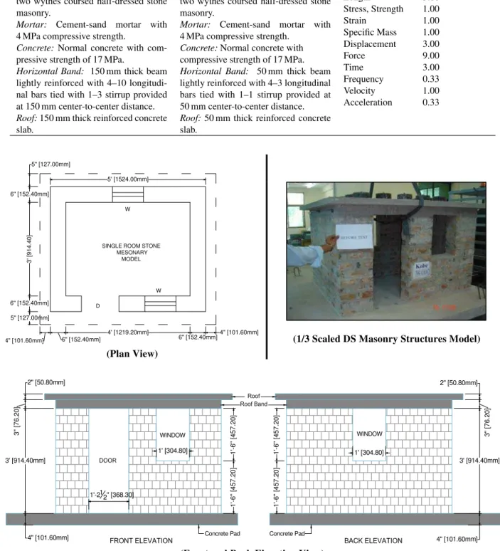
2.2 Model description
Description: A two-story office building situated in Mansehra City, Pakistan. It was subjected to the 2005 Kashmir earthquake Mw 7.6 at a distance of about 40 km from seismic source.
Minor diagonal shear cracks observed in load-bearing walls.
Horizontal large cracks developed between the floor and walls.
Separation of paint coating is observed in slab and walls.
Delamination of wall is observed whereby stone units fell out of walls.
Fig. 2.A moderately damaged half-dressed stone DS masonry structure.From left to right:view of the building and description of the observed main damages in the building.
(Tomazevic, 2000; Ali et al., 2012). A scale factor of 3 is used to reduce the dimensions of the model, whereas a scale fac-tor of 1 is used for scaling the mechanical properties (stress-strain constitutive law) of materials (stone units, mortar, ma-sonry, concrete, steel).
Table 1 reports the characteristics of the simple model and similitude requirements for model-to-prototype conversion of quantities. Figure 3 shows details of the building model tested at the Earthquake Engineering Center of UET Pe-shawar.
2.3 Testing program
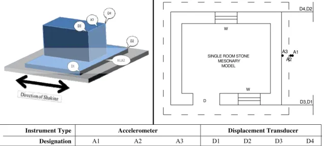
2.3.1 Model setup and instrumentation
The structure model was built on a strong concrete pad which was firmly connected to the shake table by means of bolts. The model was tested in the weaker direction. Three ac-celerometers were installed on the model: two at the base to record the input excitation and one at the roof level to record the response acceleration of the model. Four displacement transducers were installed to record the displacement time history of the model: two at the base of the model and two at the roof level. The difference of the top and bottom transduc-ers will provide an estimate of the relative lateral deformation of the model. All the gauges were connected to a data acqui-sition system where the data (acceleration and displacement time history) were recorded at a time step of 0.005 s. Cam-eras were installed to continuously monitor the behavior of
the model. Figure 4 provides details on the instrumentation of building model.
2.3.2 Characteristics of input excitation
The North–South component of the Kobe 1995 record is used for the dynamic excitation of the model. The acceleration record is modified to respect the prototype to model simili-tude requirements (Tomazevic, 2000). The time duration and predominant period of the record was reduced by 3. It re-sulted in a compressed acceleration time history with peak ground acceleration (PGA) of 0.83 g, predominant period of 0.12 s and total duration of 10 s.
2.3.3 Testing scheme
Table 1.Characteristics of the simple test model and similitude requirements for quantities conversion.
Characteristics of The Tested Model Similitude Requirements for Simple Model
Prototype building
Load-bearing walls: 450 mm thick two wythes coursed half-dressed stone masonry.
Mortar: Cement-sand mortar with 4 MPa compressive strength.
Concrete: Normal concrete with com-pressive strength of 17 MPa.
Horizontal Band: 150 mm thick beam lightly reinforced with 4–10 longitudi-nal bars tied with 1–3 stirrup provided at 150 mm center-to-center distance. Roof:150 mm thick reinforced concrete slab.
1/3 Scaled model building
Load-bearing walls: 150 mm thick two wythes coursed half-dressed stone masonry.
Mortar: Cement-sand mortar with 4 MPa compressive strength.
Concrete:Normal concrete with compressive strength of 17 MPa. Horizontal Band: 50 mm thick beam lightly reinforced with 4–3 longitudinal bars tied with 1–1 stirrup provided at 50 mm center-to-center distance. Roof:50 mm thick reinforced concrete slab.
Physical quantity Scale factor
Length 3.00
Stress, Strength 1.00
Strain 1.00
Specific Mass 1.00 Displacement 3.00
Force 9.00
Time 3.00
Frequency 0.33
Velocity 1.00
Acceleration 0.33
SINGLE ROOM STONE MESONARY
MODEL W
W D
5' [1524.00mm]
6" [152.40mm]
3' [
914.
4
0]
6" [152.40mm]
6" [152.40mm] 4' [1219.20mm]
6" [152.40mm] 4" [101.60mm]
4" [101.60mm] 5" [127.00mm]
5" [127.00mm]
(1/3 Scaled DS Masonry Structures Model) (Plan View)
3' [914.40mm]
4" [101.60mm]
3" [76.
2
0]
2" [50.80mm]
1
'-6
" [4
57
.20
]
1'-212" [368.30]
1'-6" [
4
57
.2
0
]
3' [914.40mm]
3"
[
7
6.2
0
]
2" [50.80mm]
1
'-6
" [4
57
.20
]
1'-6" [
4
57
.2
0
]
WINDOW WINDOW
Concrete Pad
1' [304.80] 1' [304.80]
4" [101.60mm] Concrete Pad
(Front and Back Elevation View)
YouTube videos database maintained by EERI Institute of USA (http://www.youtube.com/watch?v=r8JDj-DFzJs). 2.4 Observed behavior and damage mechanism 2.4.1 Global performance under input excitation The first test run at PGA of 0.04 g did not cause any appre-ciable damage in the model. The building behaved primarily in a boxlike manner. A horizontal crack was developed be-tween the walls and ring beam during the second test run at PGA of 0.08 g. Slight cracks were also developed in the in-plane and out-of-in-plane walls. The building collapsed during the third test run at PGA of 0.20 g.
2.4.2 Observed main damages
During the last test cracks developed in the in-plane and out-of-plane walls, which widened largely with increased shaking intensity. Damage in the in-plane walls included di-agonal, horizontal and inclined pattern cracks. Horizontal and inclined cracks developed in the out-of-plane walls. The widening of cracks and separation of roof from walls upon increased shaking intensity led to extensive damage in the in-plane walls, delamination of stone units from the out-of-plane walls, damage to corners and consequent stone falling, out-of-plane collapse of walls and complete collapse of the building model. The observed behavior of the model in the initial stages were comparable with the observed damages in the recent 2005 Kashmir earthquake for public buildings (see Fig. 2).
2.4.3 Observed global damage mechanism and comparison with EMS-98 scale
The behavior of the model was closely monitored during the last run to deduce damage states of the buildings and develop a damage scale towards performance-based assessment of the building for future applications. Figure 5 reports the global damage states of the building observed during the test with increased shaking level. The observed damage states are also compared with the EMS-98: European Macroseismic Scale (Grunthal et al., 1998) for masonry buildings. It is a standard scale adopted in Europe for masonry building damage rating within the context of post-earthquake screening, vulnerabil-ity and fragilvulnerabil-ity analysis. It is observed that the two scales are comparable for DS1 and DS2 damage states. However, the EMS-98 damage scale seems more conservative for DS3 and DS4 limit states, i.e. the extent of building damage spec-ified by the EMS-98 scale is more than the observed dam-ages in the considered building. The observed damage, par-ticularly of the floor, is different than the EMS-98 specified damage pattern. The floor for the considered building failed in an abrupt manner upon the complete damage and spalling of load-bearing walls, which is due to the rigid nature of the floor and its monolithic connection with the walls. This type
of roof collapse was also observed during the 2005 Kash-mir earthquake for block masonry buildings with monolithic RCC roof slab (Bothara and Brzev, 2011). Generally, the typ-ical roof used for European masonry buildings is composed of timber, roof trusses braced with timber, covered with an iron sheet (in some cases) and roof tiles. For these types of buildings, the tiles from the roof detach in a progressing man-ner during earthquakes, unlike the rigid RCC slab employed for the considered buildings.
2.4.4 Damage mechanism of component walls
The behavior of individual component walls, i.e. in-plane walls and out-of-plane walls, were also closely monitored with increased shaking level, in order to fully understand the seismic response of each component wall. Figure 6 re-ports the damage mechanism and cracking propagation for each component wall. It can be observed that the response of rubble masonry structure is very complex, which is due to the random nature of rubble masonry and rough construction work.
For example, one of the piers (with similar characteristics) of the in-plane wall developed diagonal shear mechanism, whereas the other pier developed sliding and rocking mech-anism, with progressing disintegration of piers. Such com-plex behavior, which is due to the random nature of masonry, cannot be simulated with available numerical tools and thus presents a challenge for computing tools for seismic behav-ior assessment of rubble stone masonry buildings. This fact also point to the importance of experimental investigation of rubble masonry buildings for understanding the seismic be-havior and evaluating the seismic performance.
2.4.5 Dynamic characteristics of the building model: walls
The low amplitude input excitation (PGA 0.04 g) was pri-marily meant to help retrieve the elastic dynamic proper-ties of the model, including fundamental vibration period T0and damping coefficient ζ. Both the vibration periodT0
and damping were obtained from the response acceleration time history (Fig. 7). The period is obtained using the basic definition of period of an oscillating body (i.e. the time re-quired for a complete oscillation). An average value of 0.07 s is obtained for the vibration period. The decay function for the time history of the response acceleration as proposed by Chopra (2003) is used to calculate the model damping
ζ = 1
2nπLn
A
1
An
, (1)
where ζ represents elastic damping coefficient; A1
SINGLE ROOM STONE MESONARY
MODEL W
W
D D3,D1
A3 D4,D2
A1 A2
Instrument Type Accelerometer Displacement Transducer
A1 A2 A3 D1 D2 D3 D4
Designation
Figure 4 Testing setup and instrumentation details of the building model tested on shake table at the Earthquake
Fig. 4.Testing setup and instrumentation details of the building model tested on shake table at the Earthquake Engineering Center of Peshawar.
gives an estimate of 4.008 % for damping using the positive peaks and 5.404 % using the negative peaks. On average a damping value of 4.71 % is computed, which may be approx-imated as 5 % for the building model.
3 Fragility assessment of half-dressed stone DS masonry structures
3.1 Seismic assessment framework
Many available techniques may be employed to derive the fragility functions of structures (Borzi et al., 2008; Calvi et al., 2006; Crowley, 2004; Coburn and Spence, 2002; D’Ayala et al., 1997; Erberik, 2008; Kappos and Panagopoulos, 2010; Porter et al., 2007; Rota et al., 2010, among others). The present study included a fully probabilistic, nonlinear, dy-namic reliability-based method (NDRM) recently developed by Ahmad (2011) for the seismic performance evaluation and fragility analysis of considered structure, as employed re-cently for other structure types (Ahmad et al., 2012a, b). This method is found to provide reasonable estimates of building damageability when compared with earthquake observations in Pakistan (Ahmad et al., 2012c).
The NDRM is a probabilistic method for calculating the damage exceedance probability of structures for a specified ground motion. The method of incremental dynamic analy-sis (IDA) proposed by Vamvatsikos and Cornell (2002) was used to derive the structure response curve that correlates the shaking intensity with the drift demand. The method incor-porates total uncertainties in the drift demand. The drift de-mand on structure is convolved then with the structure drift capacity for a specified limit state to obtain the exceedance probability of target limit state at a given shaking level. It is
carried out for all the intensity levels to allow the derivation of fragility functions.
3.2 Mathematical modeling
Other available, more or less sophisticated modeling tech-niques may be calibrated for global seismic analysis of ma-sonry buildings (Magenes and Fontana, 1998; Galasco et al., 2002; Kappos et al., 2002). However, these methods can-not be confidently extended for seismic response evaluation of rubble masonry buildings due to its complex behavior as observed during the experimental investigation. The present study included single degree of freedom (SDOF) mathemati-cal model for seismic analysis. The SDOF system is assigned with observing the global lateral force-deformation response of the building simulating the lateral stiffness, strength and deformation capacity of the tested building model. Thus, fully respecting the fundamental response parameters impor-tance for global dynamic seismic analysis and response eval-uation of buildings (Elnashai and Di-Sarno, 2008).
The SDOF system is assigned with lateral force-deformation constitutive law, which is derived from the ob-served response of the model, i.e. the peak drift and the cor-responding base shear observed during each test run. The model is assigned with the mass of the building model, which is adjusted to achieve the fundamental vibration pe-riod (T00.07 s) of the model as observed during the test. The
Damage Description and Comparison with EMS Damage Scale Damage States
Present Study EMS-98
Grade–1: DS1
Slight diagonal cracks are initiated in walls parallel to excitation direction.
Negligible to slight damage, No structural damage, slight non-structural damage.
Horizontal cracks initiated at the opening base corner of walls parallel to excitation, likely to forming short pier.
Hair-line cracks in very few walls.
Horizontal cracks initiated between walls and roof.
Fall of small pieces of plaster only.
Vertical cracks initiated at the end of walls parallel to excitation direction, likely to form failure plane for detachment of walls perpendicular to excitations i.e. face loaded walls.
Fall of loose stones from upper parts of buildings in very few cases.
Remarks: comparable damage state.
Horizontal cracks initiated in the face loaded walls at mid-height and top of wall.
Inclined cracks initiated in the face loaded walls, likely to form a wedge for out-of-plane failure.
Grade–2: DS2
Diagonal cracking increased in walls parallel to excitation direction.
Moderate damage,
Slight structural damage, moderate non-structural damage. Horizontal cracks developed at the opening
base and top corners of walls parallel to excitation, short pier is formed.
Cracks in many walls.
Fall of fairly large pieces of plaster.
Horizontal cracks fully developed between
walls and roof. Partial collapse of chimneys. Inclined cracks developed at the end of walls
parallel to excitation direction, failure plane for detachment of face loaded wall is developed.
Remarks: comparable damage state.
Horizontal cracks fully developed in the face loaded walls at mid-height and top of wall. Inclined cracks developed in the face loaded walls, a wedge for out-of-plane failure is formed.
Grade–3: DS3
Diagonal cracking widened significantly in walls parallel to excitation direction.
Substantial to heavy damage, Moderate structural damage, Horizontal cracks developed at the opening
base and top corners of walls parallel to excitation, short pier is formed to slide and rock.
heavy non-structural damage. Large and extensive cracks in most walls.
Horizontal cracks fully developed between walls and roof.
Inclined cracks fully developed at the end of walls parallel to excitation direction, detachment of face loaded wall is likely to occur.
Roof tiles detach. Chimneys fracture at the roof line; failure of individual non-structural elements (Partitions, Gable Walls)
Remarks: conservative damage state.
Horizontal cracks fully developed in the face loaded walls at mid-height and top of wall. Top wall portion is likely to rock.
Inclined and horizontal cracks developed in the face loaded walls, a wedge is likely to separate.
Grade–4: DS4
Diagonal cracking widened extensively in walls parallel to excitation direction.
Very heavy damage, Heavy structural damage, Horizontal cracks fully formed at the opening
base and top corners of walls parallel to excitation, short pier is responding through in-plane sliding and rocking.
Very heavy non-structural damage.
Serious failure of walls; partial structural failure of roofs and floors.
The face loaded wall fully detached from walls parallel to excitation direction, separating a wing from transverse walls. The face loaded wall fully developed horizontal crack at the top, base and mid-height, forming three pivot points for rocking.
Remarks: conservative damage state.
A wedge like portion started falling in out-of-plane direction from the face loaded walls. The structure is at the verge of total collapse.
Figure 5. Global damage mechanism of half-dressed stone DS masonry building model retrieved through
Damage Pattern with Increasing Shaking Intensity
Right
P
ier (Diagonal Shear Damages)
Left Pier (Shear Sliding
and
Rocki
ng)
ζ
Tra
nsv
erse Wa
ll (O
ut-o
f-Pla
ne
Dela
mina
tio
n
and Colla
p
se
)
⎟⎟ ⎠ ⎞ ⎜⎜ ⎝ ⎛ π = ζ
ζ
Figure 6. Local damage mechanism of half-dressed Fig. 6.Local damage mechanism of half-dressed stone DS masonry walls observed during shake table test.From top to bottom:damages observed in in-plane and out-of-plane walls.
40 42 44 46 48 50 -0.06
-0.04 -0.02 0 0.02 0.04 0.06
Time(sec)
Res
p
o
n
se A
ccel
erat
io
n
(g
)
Building Model Free Vibration
(Response Acceleration)
Figure 7. Dynamic characterization of building model u
47 47.1 47.2 47.3 47.4 47.5 -0.02
-0.015 -0.01 -0.005 0 0.005 0.01 0.015 0.02
Time(sec)
Res
p
o
n
se A
ccel
erat
io
n
(g
)
3 Cycles in 0.215 Secs 3 Cycles in 0.21 Secs
(47.05,0.0078g)
(47.26,0.0037g)
(47.015,0.01g)
(47.23,0.0036g)
(Building Model Free Vibration)
l under 0.04g input excitation. model
Fig. 7.Dynamic characterization of building model under 0.04 g in-put excitation.From top to bottom:model response acceleration and free vibration time history processed for the estimation of building vibration period and elastic damping coefficient.
(Chopra, 2003) withγ=0.5 andβ=0.25. A time step equal to the sampling size of the ground motion record is consid-ered in the analysis.
0 0.2 0.4 0.6 0.8 1 0
0.05 0.1 0.15 0.2
Drift (%)
Bas
e Sh
ear Co
effi
ci
en
t
k i
-0.10ki 0.03ki
0.16ki
BSC = 0.33BSCmax
θ(%) = 0.02
BSC = BSCmax
θ(%) = 0.50
BSC = 0.80BSCmax
θ(%) = 0.16
(Experimentally Derived)
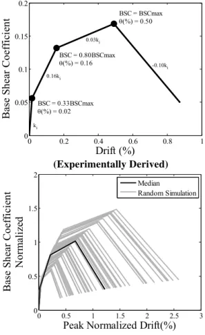
Figure 8 Lateral force-deformation constitutive law of DS
0 0.5 1 1.5 2 2.5 3 0
0.5 1 1.5 2
Peak Normalized Drift(%)
Bas
e Sh
ea
r
Co
ef
fi
ci
en
t
Nor
m
aliz
ed
Median
Random Simulation
θ
θ
θ
(Randomly Generated, Fifty Simulations)
Fig. 8.Lateral force-deformation constitutive law of DS masonry structures.From top to bottom: constitutive law obtained exper-imentally and randomly generated for SDOF mechanical model. The lateral force in the later case is normalized by the peak lateral strength.
The randomly simulated constitutive laws assigned to each of the fifty SDOF systems are also shown in Fig. 8.
3.3 Selection and scaling of accelerograms
The NDRM method requires accelerograms to perform the nonlinear dynamic time history analysis as part of the IDA of structures. A suite of ten natural accelerograms are ob-tained from the PEER NGA strong motions database. The ac-celeration response spectrum of the selected accelerograms is compatible with the building code specified spectrum for type D soil of NEHRP classification (BCP, 2007). The ac-celerograms were also selected and used elsewhere (Ahmad et al., 2012a, b, c; Menon and Magenes, 2011). The accelero-grams are normalized, anchored to common PGA, and lin-early scaled to multiple shaking levels for IDA of each SDOF system.
Table 2.Damage scale considered for fragility functions derivation.
Limit States (LS) versus Damage State (DS) Drift Limits
LS1: Damage level Grade-1 DS1 will be attained. θ1=0.7θy LS2: Damage level Grade-2 DS2 will be attained. θ2=1.5θy LS3: Damage level Grade-3 DS3 will be attained. θ3=0.5 θy+θu LS4: Damage level Grade-4 DS4 will be attained. θ4=θu
whereθirepresents the mean target drift limit states;θyrepresents the idealized yield drift limit derived from the possible bi-linearization of lateral force-deformation response of model;θurepresents the ultimate drift limits. A mean value of 0.16 % is considered forθyand 0.60 % forθu. A logarithmic standard deviation of 0.20 is considered for each of the drift limit sates.
3.4 Fragility functions
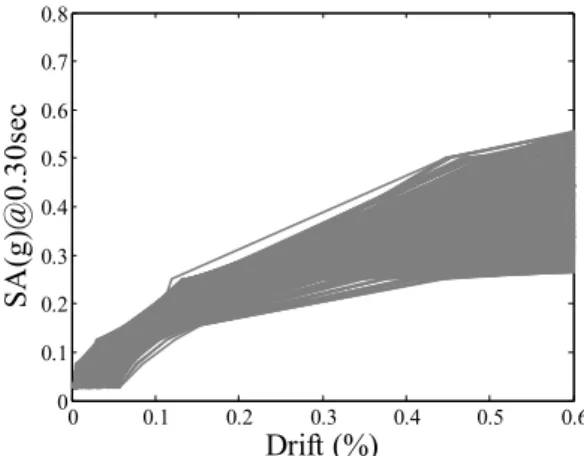
Each SDOF system is analyzed using the selected ground motions scaled to multiple PGA levels. The drift demand for each record and target PGA is obtained for all the SDOF sys-tems. The drift demand is correlated with the corresponding ground motion intensity to derive response curves for each SDOF system under each ground motion record. The mean elastic spectral acceleration, considering all the records for a target PGA, at 0.30 s is considered as the intensity measure in the present study. Figure 10 shows the response curves ob-tained for the considered structure class. The drift demand for a specified shaking level takes into account all the uncertain-ties,material uncertainties and record-to-record variability. For the fragility functions derivation, the NDRM method computes the limit state probability of exceedance for a spec-ified ground motion through the integration of the joint prob-ability density function of the drift demand and drift capac-ity. The First Order Reliability Method,FORM, approxima-tions (Der Kiureghian, 2005; Pinto et al., 2004) are employed to obtain the limit state exceedance probability. A damage scale was developed as per recommended of FEMA (2003) for the derivation of fragility functions (see Table 2). The idealized yield drift limitθywas selected such that the
dam-age state between 0.7θy and 1.5θy is a slight damage, as
per FEMA (2003) recommendation, which is roughly sim-ulated compared to the observed behavior. The ultimate drift limits θu corresponds to the lateral deformation when the
lateral force drops by 20 %, as proposed by Magenes and Calvi (1997), which corresponds to the near collapse limit state. This limit state in our study approximately corresponds to the near collapse limit state as the strength drops very rapidly after the ultimate limit state (see Fig. 8).
0 1 2 3 4 5 0 0.5 1 1.5 2 2.5 3 3.5 4 4.5 Period (sec) S p ec tr al A cc e le ra tion ( 1 /P G A
) BCP-2007, D SoilMean Spectrum
Individual Record
0 1 2 3 4 5
0 0.5 1 1.5 2 Period (sec) S p ec tr a l Dis p la c eme nt ( 1 /P G D
) BCP-2007, D Soil Mean Spectrum Individual Record
(EC8 Specified PGD at Target PGA 0.4g-Normalized Spectrum) (PGA-Normalized Spectrum)
(Details of Individual Record)
Fig. 9.Characteristics of the accelerograms used in the present study.From left to right and top to bottom: acceleration response spectrum, displacement response spectrum and details of the individual record.
0 0.1 0.2 0.3 0.4 0.5 0.6
0 0.1 0.2 0.3 0.4 0.5 0.6 0.7 0.8 Drift (%) SA (g )@ 0 .3 0 sec
Figure 10 Structure response curves obtained
Fig. 10.Structure response curves obtained through IDA of SDOF systems.
P[D≥dLS/SA=sa]8
1 βLn SA saLS , (2)
whereP represents the limit state probability of exceedance; 8 represents the standard normal cumulative distribution function;β represents the logarithmic standard deviation of fragility function; SA represents the seismic intensity; and
θ
θ
θ
θ
θ = θ θ = θ(
θ +θ)
= θ θ = θ
θ
θ
θ
θ
θ
[
]
⎟⎟ ⎠ ⎞ ⎜ ⎜ ⎝ ⎛ ⎟⎟ ⎠ ⎞ ⎜⎜ ⎝ ⎛ β Φ = = ≥0 0.2 0.4 0.6 0.8 1
0 0.2 0.4 0.6 0.8 1 SA(g)(0.30sec,5%) P roba bility of Ex ce eda nc e LS1(0.15,0.31) LS2(0.25,0.31) LS3(0.33,0.31) LS4(0.45,0.31) NDRM
Fig. 11.Fragility functions for Himalayan DS masonry structures obtained through NDRM.
saLSrepresents the median estimate of the distribution. The
values ofβandsaLSare also provided in Fig. 11. The
0 0.2 0.4 0.6 0.8 1 0
20 40 60 80 100
SA(g)(0.30sec,5%)
Ec
ono
m
ic
Loss R
atio (
%
) ELR(0.38,0.37)
EL = (ELR/100)xNxC
where
El = Economic Losses ELR = Economic Loss Ratio N = Number of Buildings C = Replacement Cost of Building
Fig. 12.Vulnerability function for Himalayan DS masonry struc-tures obtained using the FEMA (2003) economic consequence fac-tor.
3.5 Vulnerability functions
The impact of an earthquake on the built environment is com-puted in terms of monetary losses and human casualties. The monetary losses correspond to the economic losses the au-thority has to bear to bring the devastated society to habit-able condition. It includes the direct losses due to building damage and indirect losses, including business downtime and loss of means of income besides the response and relief ex-penditure. The direct economic losses related to the build-ing damage represent the amount required to pay for the re-pair, demolishment and replacement of structures damaged in earthquakes (Bal et al., 2008; FEMA, 2003). Only the di-rect economic losses are considered in the present research study. The human casualties include the number of people injured and trapped in the collapsed buildings which are es-sential for rescue operation soon after the earthquake (Erdik et al., 2011; Hancilar et al., 2010). The casualties may be fur-ther classified into minor, moderate and serious injuries and deaths (Spence, 2007b).
Vulnerability function for economic losses is derived from the building fragility functions. It included the estimation of probability of building damages at a specified shaking intensity, which are convolved with the economic conse-quence factor ECF (Ahmad, 2012c), where ECF refers to the scale relating building damage with the monetary losses. The FEMA model which assigns a cost ratio (the ratio of damaged building repair to replacement cost) of 0.02 for DS1, 0.10 for DS2, 0.50 for DS3 and 1.0 for DS4, is em-ployed herein to derive vulnerability curve for the consid-ered DS masonry building. Figure 12 reports the vulnerabil-ity curve for the considered DS masonry structures where the losses are represented in terms of the economic loss ratio. The function can be used to compute the economic losses for the structures during earthquake given the shaking intensity (SA @ 0.30 s).
0 0.5 1 1.5 2
0 10 20 30 40 50
SA(g)(0.30sec,5%)
Hum
an Loss R
atio (
%)
Slight Injuries
Serious Injuries & Fatalities Critical Injuries
Moderate Injuries HL = (HLR/100)xNxO
where
Hl = Human Injuries HLR = Human Loss Ratio N = Number of Buildings O = Occupants Per Building
Figure 13 Vulnerability functions for Himalayan
Fig. 13.Vulnerability functions for Himalayan DS masonry struc-tures obtained using the Spence (2007b) human consequence factor.
Vulnerability functions for human casualties are derived from the collapse fragility function of the buildings. For this purpose the human consequence factor (HCF) developed by Spence (2007b) is employed in the present study. It includes the convolution of the collapse fragility function with the loss ratio of the Spence model. This model assigns ratio of slight injuries with 0.50, moderate injuries with 0.12, seri-ous injuries with 0.08 and critical injuries and deaths with 0.064 in collapsed buildings. Figure 13 reports the vulnera-bility functions derived for the casualty estimation in earth-quakes. The losses are represented in terms of the Human loss ratio, which can provide estimates of human casualties in collapsed buildings during earthquake given the shaking intensity (SA @ 0.30 s).
4 Seismic risk of DS masonry structures in scenario earthquakes
The present study also included case studies for risk assess-ment of considered DS masonry structures in large scenario earthquakes. Three scenario earthquakes withMw=7.0, 7.5
and 8.0 are considered, for which building damageability is assessed at various source-to-site distances. Each of the sce-nario earthquake ground motions is simulated with 1000 dif-ferent ground motion fields, considering uncertainties in the ground motions estimate. Empirical ground motion predic-tion equapredic-tions (GMPEs) are used to estimate ground mopredic-tions (Abrahamson and Silva, 2008; Boore and Atkinson, 2008; Campbell and Bozorgnia, 2008).
Rjb = 0 – 10km Rjb = 10 – 20km Rjb = 20 – 30km Rjb = 30 – 40km Rjb = 40 – 50km
DS1 DS2 DS3 DS4 0
20 40 60 80 100
DS1 DS2 DS3 DS4 DS1 DS2 DS3 DS4 DS1 DS2 DS3 DS4 DS1 DS2 DS3 DS4
DS1 DS2 DS3 DS4 0
20 40 60 80 100
DS1 DS2 DS3 DS4 DS1 DS2 DS3 DS4 DS1 DS2 DS3 DS4
DS1 DS2 DS3 DS4
DS1 DS2 DS3 DS4
DS1 DS2 DS3 DS4 0
20 40 60 80 100
DS1 DS2 DS3 DS4 DS1 DS2 DS3 DS4
DS1 DS2 DS3 DS4
Fig. 14.Damageability (percentage of total stock) of DS masonry structures in scenario earthquakes. From top to bottom: Damageability forMw=7.0, Damageability forMw=7.5 and Damageability forMw=8.0. DS1 represents slight damages; DS2 represents moderate damages; DS3 represents heavy damages.
estimate of the percentage of structures with various damage levels.
The observed damageability of the considered structure type seems very high. It can be observed that more than 40 percent of the stock may collapse during earthquake with Mw equal or greater than 7.0, for buildings located in the near and intermediate field. The percentage of collapsed struc-tures can even rise to 70–80 during large earthquakes and for buildings located in close source-to-site distance. This huge percentage of damageability will consequently result in highly associated socio-economic losses. This high vulnera-bility of the considered building type gives merit to the use of simple retrofitting interventions, as investigated by Ali et al. (2012), to mitigate the risk of vulnerable stone masonry buildings in the future expected large earthquake.
5 Conclusions
The paper presents a study carried out as part of the search aiming towards risk mitigation and disaster risk re-duction in the Himalayan region, which could be subjected to very large earthquakes in the future. Half-dressed ma-sonry structures representing public critical facilities in the region are considered for investigation, a very common type in the region. Fragility functions are derived for the con-sidered construction type using experimental and numerical investigations. Furthermore, vulnerability functions are de-rived for economic loss estimation and human casualty esti-mation. The derived fragility and vulnerability functions are employed for earthquake scenario risk assessment
consid-ering moderate and large magnitude earthquakes. The con-sidered construction type exhibits high vulnerability against earthquakes. Up to 40 percent of building stock can collapse in large earthquakes, where the percentage of collapse can rise as high as 70–80 for large earthquakes with close source-to-site distance. The present study can be employed for com-municating the expected risk level to public authorities to take measures aiming towards risk mitigation and disaster risk reduction. This can in turn result in the mitigation of eco-nomic losses from future earthquakes. The findings from the present study can also be employed for rapid earthquake loss estimation within the context of prompt response to disaster sites, essential for rescue operation and emergency planning that can reduce human casualties in earthquakes.
Supplementary material related to this article is available online at:
http://www.nat-hazards-earth-syst-sci.net/12/3441/2012/ nhess-12-3441-2012-supplement.zip.
Acknowledgements. The reviewers’ effort in evaluating the manuscript and kindly providing encouraging remarks is highly appreciated. The experimental study presented herein is financially supported by the Board of Advanced Studies and Research (BOASAR) of the University of Engineering & Technology (UET) Peshawar and the Higher Education Commission (HEC) of Pakistan, which are gratefully acknowledged.
Edited by: M. E. Contadakis
References
Abrahamson, N. and Silva, W.: Summary of the Abrahamson and Silva NGA ground-motion relations, Earthq. Spectra, 24, 67–97, 2008.
Adanur, S.: Performance of masonry buildings during the 20 and 27 December 2007 Bala (Ankara) earthquakes in Turkey, Nat. Hazards Earth Syst. Sci., 10, 2547–2556, doi:10.5194/nhess-10-2547-2010, 2010.
Ahmad, N.: Seismic risk assessment and loss estimation of building stock of Pakistan, PhD Thesis, ROSE School-IUSS Pavia, Pavia, Italy, 2011.
Ahmad, N., Ali, Q., Ashraf, M., Naeem, A., and Alam, B. Seismic performance evaluation of reinforced plaster retrofitting tech-nique for low-rise block masonry structures, Int. J. Earth Sci. Eng., 5, 193–206, 2012a.
Ahmad, N., Ali, Q., and Umar, M.: Seismic vulnerability assess-ment of multistorey timber braced frame traditional masonry structures, Appl. Mech. Materials – Trans Tech Publications, ac-cepted, 2012b.
Ahmad, N., Ali, Q., Crowley, H., and Pinho, R. Earthquake loss es-timation of structures in Pakistan, in Proceedings of the 9CUEE & 4ACEE, Tokyo, Japan, 2012c.
Akkar, S., Aldemir, A., Askan, A., Bakir, S., Canbay, E., Demirel, I. O., Erberik, M. A., Gulerce, Z., Gulkan, P., Kalkan, E., Prakash, S., Sandikkaya M. A., Sevilgen, V., Ugurhan, B., and Yenier, E.: 8 March 2010 Elazıg-Kovancılar (Turkey) Earthquake: Observa-tions on Ground MoObserva-tions and Building Damage, Seismol. Res. Lett., 82, 42–58, 2011.
Ali, Q. and Mohammad, T. Stone masonry residential buildings in northern areas of Pakistan. Housing Report, Earthquake Engi-neering Research Institute (EERI), Oakland, CA, USA, 2006. Ali, Q., Naeem, A., Ashraf, M., Ahmed, A., Alam, B., Ahmad,
N., Fahim, M., Rahman, S., and Umar, M.: Seismic performance of stone masonry buildings used in the Himalayan Belt, Earthq. Spectra, accepted, , 2012.
Avouac, J., Ayoub, F., Leprince, S., Konca, O., and Helmberger, D. V.: The 2005 Mw 7.6 Kashmir earthquake: Sub–pixel correlation of ASTER images and seismic waveforms analysis, Earth Planet. Sci. Lett., 249, 514–528, 2006.
Bal, I. E., Crowley, H., Pinho, R., and Gulay, G.: Detailed Assess-ment of Structural Characteristics of Turkish RC Building Stock for Loss Assessment Model, Soil Dynam. Earthquake Eng., 28, 914–932, 2008.
BCP-2007: Building Code of Pakistan–Seismic provision 2007, Technical Document, Ministry of Housing and Works, Islam-abad, Pakistan, 2007.
Bilham, R.: Earthquakes in India and in the Himalaya: tectonic, geodesy, and history, Ann. Geophys., 47, 839–858, 2004, http://www.ann-geophys.net/47/839/2004/.
Boore, D. M. and Atkinson, G. M.: Ground-motion prediction equa-tions for the average horizontal component of PGA, PGV, and 5 %–damped PSA at spectral periods between 0.01s and 10.0s, Earthq. Spectra, 24, 99–138, 2008.
Borzi, B., Crowley, H., and Pinho, R. Simplified pushover–based earthquake loss assessment (SP–BELA) method for masonry buildings, Int. J. Architectural Heritage, 2, 353–376, 2008. Bothara, J. and Brzev, S. A. Tutorial: Improving the seismic
per-formance of stone masonry buildings, Earthquake Engineering Research Institute (EERI), Oakland, CA, USA, 2011.
Calvi, G. M., Pinho, R., Magenes, G., Bommer, J. J., Restrepo-Velez, L. F., and Crowley, H.: Development of seismic vulner-ability assessment methodologies over the past 30 years, ISET J. Earthqu. Technol., 43, 75–104, 2006.
Campbell, K. and Bozorgnia, Y.: NGA ground motion model for the geometric mean horizontal component of PGA, PGV, PGD and 5 % damped linear elastic response spectra for periods ranging from 0.01 to 10s, Earthq. Spectra, 24, 139–171, 2008.
Chopra, A. K.: Dynamics of structures: Theory and applications to earthquake engineering, 3rd Edition, Prentice-Hall, NJ, USA, 2003.
Coburn, A. and Spence, R. Earthquake Protection. John Wiley and Sons, Ltd., West Sussex, England, 2002.
Crowley, H., Pinho, R., and Bommer, J. J.: A probabilis-tic displacement-based vulnerability assessment procedure for earthquake loss estimation, Bull. Earthq. Eng., 2, 173–219, 2004. D’Ayala, D., Spence, R., Oliveira, C., and Pomonis, A. Earthquake loss estimation for Europe’s historic town centers, Earthq. Spec-tra, 13, 773–793, 1997.
Der Kiureghian, A.: First- and second-order reliability methods, edited by: Nikolaidis, E., Ghiocel, D. M., and Singhal, S., in: Engineering Design Reliability Handbook, CRC Press 2005. EERI: Learning from Earthquakes: The Kashmir earthquake of
Oc-tober 8, 2005: impacts in Pakistan. EERI Special Earthquake Re-port, Earthquake Engineering Research Institute (EERI), Oak-land, CA, USA, 2006.
EERI: Learning from Earthquakes: The Mw 6.9 Sikkim-Nepal bor-der earthquake of September 18, 2011. EERI Special Earthquake Report, Earthquake Engineering Research Institute (EERI), Oak-land, CA, USA, 2012.
Elnashai, A. S. and Di-Sarno, L.: Fundamentals of earthquake engi-neering. John Wiley and Sons Ltd., West Sussex, UK, 2008. Erberik, M. A.: Generation of fragility curves for Turkish masonry
buildings considering in-plane failure modes, Earthquake Eng. Struct. Dynam., 37, 387–405, 2008.
Erdik, M., Sesetyan, K., Demircioglu, M. B., Hancilar, U., and Zul-fikar, C. Rapid earthquake loss assessment after damaging earth-quakes, Soil Dynam. Earthq. Eng., 31, 247–266, 2011.
FEMA: Multi-hazard loss estimation methodology, earthquake model. HAZUS-MH Technical Manual, Federal Emergency Management Agency (FEMA), Washington, DC, USA, 2003. Galasco, A., Lagomarsino, S., and Penna, A.: TREMURI Program:
Seismic analyses of 3D masonry buildings, University of Genoa, Genoa, Italy, 2002.
Grunthal, G., Musson, R. M. W., Schwarz, J., and Stucchi, M.: EMS-98: European Macroseismic Scale, Centre Europ`een de G´eodynamique et de S´eismologie, Luxembourg, 1998.
Gulkan, P., Sucuoglu, H., and Ergunay, O.: Earthquake vulnerabil-ity, loss and risk assessment in Turkey. Proceedings of the Tenth World Conference on Earthquake Engineering, Madrid, Spain, 1992.
Gupta, I., Shankar, R., and Sinvhal, A. Earthquake vulnerability as-sessment of house constructions in Himalayas, J. Design Built Environ, 3, 1–14, 2008.
Ingham, J. and Griffith, M. C.: The Performance of Unreinforced Masonry Buildings in the 2010/2011 Canterbury Earthquake Swarm, Technical Report, Royal Commissions and Commis-sions of Inquiry, Wellington, New Zealand, 2011.
Javed, M., Naeem, A. and Magenes, G.: Performance of masonry structures during earthquake-2005 in Kashmir, Mehran Univer-sity Res. J. Eng. Technol., 27, 271–282, 2008.
Kappos, A. and Panagopoulos, G.: Fragility curves for reinforced concrete buildings in Greece. Structure and Infrastructure Engi-neering: Maintenance, Management, Life-Cycle Design and Per-formance, 6, 39–53, 2010.
Kappos, A. J., Penelis, G. G., and Drakopoulos, C. G.: Evaluation of simplified models for lateral load analysis of unreinforced ma-sonry buildings, J. Struct. Eng., 128, 890–897, 2002.
Kaushik, H. B., Dasgupta, K., Sahoo, D. R., and Kharel, G.: Perfor-mance of structures during the Sikkim earthquake of 14 February 2006, Curr. Sci., 91, 449–455, 2006.
Kircher, C. A., Nassar, A. A., Kustu, O., and Holmes, W. T.: Devel-opment of building damage functions for earthquake loss estima-tion, Earthq. Spectra, 13, 663–682, 1997.
Magenes, G. and Calvi, G. M.: In-plane seismic response of brick masonry walls, Earthq. Eng. Struct. Dynam., 26, 1091–1112, 1997.
Magenes, G. and Fontana, D.: Simplified non-linear seismic anal-ysis of masonry buildings, Proc. British Masonry Soc., 5, 190– 195, 1998.
Maqsood, S. T. and Schwarz, J.: Seismic vulnerability of existing building stock in Pakistan. Proceedings of the Fourteenth World Conference on Earthquake Engineering, Beijing, China, 2008. Menon, A. and Magenes, G.: Definition of seismic input for
out-of-plane response of masonry walls: I. parametric study, J. Earthq. Eng., 15, 165–194, 2011.
Murty, C. V. R.: Earthquake Tips: Learning seismic design and con-struction. Technical Report, Indian Institute of Technology, Kan-pur, Uttar Pradesh, India, 2003.
Naseer, A., Naeem, A., Hussain, Z., and Ali, Q. Observed seismic behavior of buildings in northern Pakistan during the 2005 Kash-mir earthquake, Earthq. Spectra, 26, 425–449, 2010.
Pinto, P. E., Giannini, R., and Franchin, P.: Seismic reliability anal-ysis of structures. IUSS Press, Pavia, Italy, 2004.
Porter, K., Kennedy, R., and Bachman, R.: Creating fragility func-tions for performance-based earthquake engineering, Earthq. Spectra, 23, 471–489, 2007.
Rai, D. C. and Murthy, C. V. R.: Preliminary report on the 2005 north Kashmir earthquake of October 8, 2005. Field Report, In-dian Institute of Technology, Kanpur, Uttar Pradesh, India, 2006. Rota, M., Penna, A., and Magenes, G.: A methodology for deriv-ing analytical fragility curves for masonry buildderiv-ings based on stochastic nonlinear analyses, Eng. Struct., 32, 1312–1323, 2010. Scott, M. H. and Fenves, G. L.: A Krylov Subspace Accelerated Newton Algorithm: application to dynamic progressive collapse simulation of frames, J. Struct. Eng., 136, 473–480, 2010. Spence, R.: Saving lives in earthquakes: successes and failures in
seismic protection since 1960, Bulletin Earthq. Eng., 5, 139–251, 2007a.
Spence, R.: Earthquake disaster scenario predictions and loss mod-elling for urban areas, LESSLOSS Report, IUSS Press, Pavia, Italy, 2007b.
Tomazevic, M.: Some aspects of experimental testing of seismic be-havior of masonry walls and models of masonry buildings, ISET J. Earthq. Technol., 37, 101–117, 2000.