Damage index analysis of prefabricated segmental bridge columns
under cyclic loading
Abstract
The damage index is usually applied to evaluate the damage states of bridge structures, which is the basis of structural fragility study. The present study investigates the seismic damage index of the prefabricated segmental bridge columns (PSBC) under cyclic loading by theoretical and numerical analysis. Based on the previous pseudo-static experiments, different damage states characteristics of the monolithic cast-in-place bridge columns (MCBC) and the PSBC are discussed and analyzed to propose the limit-state capacities for each damage state of the PSBC. The limit-state capacities include four parameters: compressive strain of concrete, the tensile strain of steel, the prestress level and the residual displacement. Two finite element models of the PSBC are developed by OpenSees to carry on numerical analysis. Using the numerical results, the damage indexes for the PSBCs are obtained based on the limit-state capacities obtained above. The results indicate that the numerical results show good agreement with the experimental results of the bridge columns. The damage index formula of the PSBC, derived in this study, is reasonable and can be further applied. The maximum error between the proposed damage index and that obtained in the verified case is 20.3%. The proposed method in this paper for developing the damage index of the PSBC can be used in the seismic vulnerability analysis assessment of the bridge structures with prefabricated segmental columns.
Keywords
bridges, prefabricated segmental columns, damage index, seismic vulnerability analysis.
1 INTRODUCTION
The pier columns of bridge structures are easily damaged due to earthquakes. Compared with the monolithic cast-in-place bridge columns (MCBC), the prefabricated segmental bridge columns (PSBC) have advantages of speedy construction, low environmental impact, easy quality assurance and strong self-resetting ability (Billington and Breen 2000, Nikbakht et al. 2014). The prefabricated segmental bridge columns are widely applied to the lower structures of Sea-Crossing bridge approach and urban viaduct, as shown in Figure 1 (Bertsimas and Frankovich 2013, Zhang and Zhai 2018). Based on numerous seismic data under earthquakes for MCBC, lots of studies are concentrated at its seismic vulnerability analysis, and some relatively good system are proposed to evaluate the damage under earthquake. However, for PSBC, there are no good methods to measure its damage state and evaluate the seismic fragility accurately and quantitatively. The seismic vulnerability analysis of the PSBC is of great significance to the seismic design safety of bridges.
Yong Zhaia Yuye Zhanga*
a Department of Civil Engineering, Nanjing
University of Science and Technology, Nanjing 210094, China. E-mail:
[email protected], [email protected]
* * Corresponding author
http://dx.doi.org/10.1590/1679-78254986
Figure 1: Engineering applications of PSBC.
For bridge structures, the bridge columns and bearings are easily damaged under earthquake. The key components could be used to evaluate the full structures. The damage index of the full structure could be obtained by combining the damage indexes of columns, bearings, and other components, such as the abutments. Based on the damage indexes of bridge components, the damage state and corresponding damage index limit of bridge structures could be determined. Then the damage index can be used to assess the damage of the bridge structures. The research significance of this paper is to study the damage index of the traditional PSBC under cyclic loading by simulating the earthquake action (Beydokhty et al. 2016). While analyzing the seismic vulnerability, damage index is an important step to quantify the structural damage. In order to evaluate, the damage state of the MCBC is usually divided into five levels: no damage, slight damage, moderate damage, severe damage and collapse. Park and Ang (1985) proposed the seismic damage model consisting of maximum deformation and cumulative hysteretic energy dissipation along with a defined damage index formula. Some scholars have made some modifications to the damage index formula and have put forward the corresponding relationship between the damage level and the damage index (Park and Ang 1985, Stone and Taylor 1993, Hwang et al. 2000). Hwang et al. (2001) used the displacement ductility ratio to define the damage index of the MCBC considering the bending failure. Emphasizing on the displacement ductility ratio, Karim and Yamazaki (2001 and 2010) proposed a new formula for the MCBC. The damage index proposed above have been used for the seismic fragility analysis of the similar piers. Zhang et al. (2016) and Zhang and Dias-da-Costa (2017) adopted the damage index formula proposed by Karim and Yamazaki for further seismic fragility analysis of concrete bridge piers.
Limit -st at e capacit ies based on t he t heoret ical analysis
A nalysis of damage st at es f or PSBC
Numer ical model V erified model
Park-A ng DI formula for M CB C
Paramet er values Paramet er values
(for varificat ion)
β*
DI = 1 (for collapse st at e)
Damage index of t he PSBC
DI limit for each damage st at e(for varificat ion) DI limit for each damage
st at e(for varificat ion)
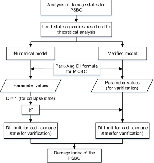
Figure 2: Flow chart of proposed method for determining the damage index of PSBC.
Aiming to obtain the damage index of the PSBC under cyclic loading, firstly, this paper investigates the damage states of the existing MCBC and PSBC based on the quasi-static tests to propose the limit-state capacity. For the analysis, OpenSees software is used to develop fiber element models. In addition, the Park-Ang damage index formula is modified to obtain reasonable formula and corresponding damage states of the PSBC. Combining the modified damage index formula and results from numerical models, the damage index limit corresponding to damage states were obtained. Finally, the method of determining the damage index was verified by another model. The flow chart of the proposed method for determining the damage index of the PSBC in this paper is shown in Figure 2.
2 ANALYSIS OF DAMAGE STATES
2.1 Damage states of columns
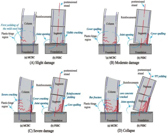
At present, the research work done upon the damage of the MCBC is relatively sufficient. The damage of the MCBC under cyclic loading is mainly concentrated on the plastic hinge region. The energy dissipation of MCBC is mainly through the non-linear behavior of concrete and its reinforcement, which consists of cracking, crushing and spalling of cover concrete and core concrete, longitudinal buckling and stirrup fracture, as shown in Figure 3(a).
prestressed tendons. The nonlinear behavior at joints is considered as the main energy dissipation method, as shown in Figure 3(b).
For the MCBC under cyclic loading, the damage mode of the MCBC mainly contains several periods and focuses on the plastic-hinge region. For slight damage, the first yielding of the mild steel bars is the main damage for the column. The cover crushing and spalling, severe cracking at the plastic-hinge region is the main damage for the moderate damage and severe damage, respectively. For the collapse, bar fracture and core concrete crushed the are the main damage for the columns. For the PSBC under cyclic loading, the damage is mainly focused on the joints between the foundation and base segment or the segments. For slight damage, the columns mainly appear the initial joint opening and visible cracking at the base segments. For moderate damage, the cover concrete spalling is appeared at the base segments. For severe damage, the reinforcements in the base segments could yield and the cover concrete may be crushed. For collapse, the core concrete at the base segments could be spalled and the prestressed tendons could yield.
Figure 3: Main damage sketch of columns under cyclic loading.
Hose et al. (2000) summarized the damage states of the MCBC (Table 1). Based on the knowledge obtained from the experimental analysis and the damage theory proposed by Park-Ang about the MCBC, the main descriptions of the damage states of the PSBC are obtained in this paper, as shown in Table 1.
Table 1: Damage states and corresponding damage characteristics.
Damage states Damage characteristics
MCBC PSBC
Slight damage Initial reinforcement yielding theoretically;
obvious cracking; Visible joint opening; initial yielding;
Moderate damage Local plastic hinges formed; nonlinear deformation appeared; cover spalling;
Longitudinal compression crack in cover; initial cracking;
Severe damage Plastic hinges formed completely; severe
cracking; concrete spalling at plastic hinge region; Concrete spalling at joint; stirrups exposed;
Collapse Strength degradation; main reinforcement yielding; stirrup fracture; core crushing;
Concrete crushing at base segment; main reinforcement yielding; tendons yielding;
2.2 Limit-state capacities
Generally, the base segment of the PSBC will open and close when subjected to cyclic loading. The main damage can be expressed by the concrete, its reinforcements, and tendons. The reinforcements will show yielding, hardening and fracturing. Compressed edge of the concrete will show compression yielding, spalling and crushing. The tendons generally appear in two states, which includes elasticity and yielding. Based upon the self-resetting characteristics of the PSBC, the residual displacement of columns can also be used as the parameter of evaluation.
The limit-state capacities of bridge components commonly serve as the threshold of the components entering prescriptive damage states, such as slight, moderate, severe and collapse (Zhang and Dias-da-Costa 2017). The limit-state capacity can be defined as a measure of the capacity of the bridge components to withstand an earthquake without exceeding the prescribed performance level (Nielson and Desroches 2012). Based on the above characteristics, the limit-state capacities of the PSBC were analyzed considering the compressive strain of the concrete, the tensile stress of the reinforcements, the prestress level of prestressed tendons and the residual displacement of columns, as shown in Table 2 (Liu 2008, Rojahn et al. 1997). Part of the details of parameters can be found in the seismic specifications for bridges of China and Japan (MOT 2004, 2008, JRA 2002). As long as any one of the four parameters meets the requirements of the values in Table 2, it can be considered that it has reached the limit point of each damage state. The method of determining the limit-state capacities can be applied to establish the damage index corresponding to damage states.
Table 2: Limit-state capacities of the prefabricated segmental bridge columns.
Damage states Compressive strain Tensile stress Prestress level Residual displacement
Slight damage 0.004 (cover) 0.015 - -
Moderate damage 0.012 (core) 0.08 - -
Severe damage 0.018 (core) 0.12 85%fptka 1%lbb
a fptk is the standard value of ultimate strength of the tendon. b lb is the effective height of the column.
3 NUMERICAL MODELING
The PSBC has greater deformation demand and capacity than the MCBC under the same seismic action. By adopting the analysis method of MCBC, seismic behavior of the PSBC cannot be evaluated properly. Therefore, it is necessary to analyze the seismic capacity of the PSBC.
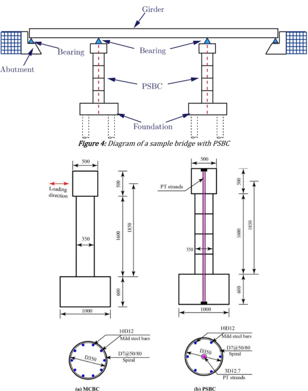
Figure 4: Diagram of a sample bridge with PSBC
Figure 5: Dimensions and reinforcements of bridge columns (unit: mm).
3.1 Finite element model
Figure 6: Diagrams of the OpenSees models.
Reinforced concrete sections are composed of core fiber with stirrups, the protective layer and reinforcement fiber. The concrete is modeled with Kent-Scott-Park material model. The reinforcement is modeled by Reinforcing-Steel material model. The tendon is modeled with the Elastic-Plastic Plastic material model. The initial prestress of the tendon is considered in the material model. The details of the material models can be found in the Command Language Manual of OpenSees (Mazzoni et al. 2001).
The zero-length element is used to model joints. Each cross section of the joints is divided into several equal parts along the loading direction, which are simulated by the zero-length spring element. In order to avoid the penetration of concrete at the joints, the stiffness of the middle spring element is set larger than that of two side spring elements to ensure the rationality of the model calculation.
3.2 Validation of the models
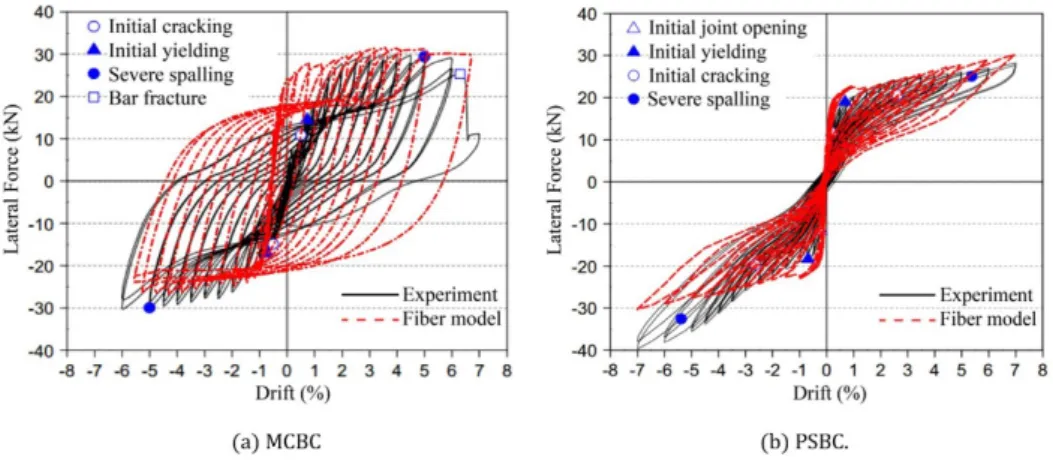
The lateral force-drift curves obtained from simulation results of the MCBC and PSBC fiber models are shown in Figure 7. There are some differences between the two columns while comparing the simulation with reference test results. The skeleton curve matches relatively well before the maximum load. Due to some imperfections in the simulation method, the strength degradation and residual displacement of MCBC are relatively larger than the test values.
Figure 7: Lateral force-drift curves.
4 DETERMINATION OF DAMAGE INDEX
4.1 Introduction of damage index
The previous study upon the damage index of the MCBC were mainly concentrated on the use of displacement ductility ratio. Energy dissipation at the bottom segments is the main damage of PSBC which is governed through non-linear behaviors such as opening and closing of joints. The displacement ductility ratio is not suitable for the definition of damage index of the PSBC because of its difference at the damage mechanism when compared with MCBC. The double failure criterion proposed by Park and Ang (1985) is adopted to get the damage index of the PSBC in this paper. The damage index formula is modified as shown in Eq. (1):
max
u y u
β δ
DI dE
δ Qδ (1)
where δmax is the maximum response deformation, which is the maximum displacement of the cyclic loading, δu is
the ultimate deformation under monotonic loading, taken from the result of Pushover analysis, Qy is the calculated
yield strength, ∫dE is the cumulative energy dissipation and β* is the modified cyclic loading factor, which can be obtained by DI=1 reversely instead of the original formula (Park and Ang 1985). The values of δu、 Qy and β* have
nothing to do with the loading history, which are the constant values in a specimen column.
4.2 Statistical analysis
The displacement, force and energy dissipation of each damage state boundary can be determined in the upper model by using the previous method for determining the limit-state capacities. The parameter values of the damage index formula are shown in Table 3.
Table 3: The parameter values of the damage index formula.
Damage states δmax (%)
a δu (%)b Qy (kN)c ∫dE (kN·mm)d
MCBC PSBC MCBC PSBC MCBC PSBC MCBC PSBC
Slight damage 0.748 0.95
8.08 8.00 21.63 16.70
296.40 53.60
Moderate damage 3.82 4.10 14078.80 2818.90
Severe damage 6.17 7.00 31136.10 7144.20
aδmax is the maximum response displacement replaced by drift (ratio of displacement to effective height of the column).
bδu is the ultimate displacement under monotonic loading replaced by drift (ratio of displacement to effective height of the column). c Qy is the calculated yield strength.
d∫dE is the cumulative energy dissipation.
For the MCBC, the δmax can be determined by taking displacement ductility ratio as the damage index from
curves. Limit 2, the minimum limit-state capacity of moderate damage and severe damage, can be defined as the displacement (drift) when compressive strain of cover concrete of the column reaches 0.004 με. Limit 3, the minimum limit-state capacity of severe damage and collapse, can be defined as the displacement (drift) when longitudinal reinforcement that near to the extreme fiber of the base section fractures.
For the PSBC, the δmax can be determined with the help of concepts and table 2 developed in the second part of
the paper. Limit 1 can be defined as the displacement (drift) when the compressive strain of the cover concrete at the base segment reaches 0.004 με, or tensile strain of the main longitudinal reinforcement reaches 0.015 με. The drift of the Limit 1 is 0.95%, which is obtained when the compressive strain of the cover concrete at the base segment reaches 0.004 με. At the same time, the tensile strain of the main tensile longitudinal reinforcement does not reach 0.015 με.
Limit 2 can be defined as the displacement (drift) when the compressive strain of the core concrete at the base segment reaches 0.012 με or the tensile strain of the tensile longitudinal reinforcement reaches 0.06 με. The drift of the Limit 2 is 4.1%, which is obtained by following the same procedure to get limit 1.
Limit 3 can be defined as the displacement (drift) when the compressive strain of the core concrete at the base segment reaches 0.018 με or the tensile strain of the main longitudinal reinforcement reaches 0.10 με or when the strength of tension reaches 80% of the yield strength or the residual drift reaches 1%. The limit of damage state will be determined as long as one of the above items is satisfied. For limit 3, the drift is 7%. The tensile strain of the main tensile longitudinal reinforcement, strength of tendon and the residual drift did not reach the corresponding limit values.
Each parameter can be brought into the formula (1) except the unknown cyclic loading factor β*. The default value of the damage index (DI) for severe damage and collapse is 1, which can be used to calculate β*. Then, the obtained β* can be brought into the formula (1) to calculate the DI values of the other damage states. Finally, the DI values corresponding to all damage states are shown in Table 4.
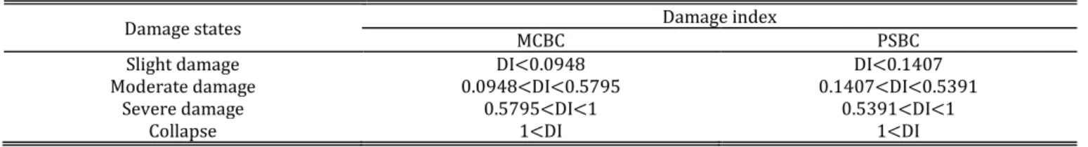
Table 4: Damage index corresponding to damage states.
Damage states Damage index
MCBC PSBC
Slight damage DI<0.0948 DI<0.1407
Moderate damage 0.0948<DI<0.5795 0.1407<DI<0.5391
Severe damage 0.5795<DI<1 0.5391<DI<1
Collapse 1<DI 1<DI
4.3 Modification of formula
The initial β formula of the Park-Ang damage index (Park and Ang 1985) can be expressed as:
( 0.4470.073l d0.24n00.314t)0.7w (2)
where l/d is the shear span ratio, n0 is the normalized axial force (replaced by 0.2 if n0<0.2), ρtand ρw are the longitudinal reinforcement ratio and the confining reinforcement ratio respectively.
The shear span ratio is the ratio of the calculated height to the section width of the column, which is still the same before and after the modification. The ρt in the original formula corresponds to the longitudinal reinforcements of the MCBC. And it plays an important role in the seismic performance under cycle loading. For the PSBC, the prestressed reinforcement ratio may be used to replace the ordinary longitudinal reinforcement ratio. However, the experience shows that the main function of tendon is to provide axial pressure and self-resetting ability. And the influence of prestressed reinforcement ratio is relatively small. Thus, the modification of the reinforcement ratio can be neglected.
When compared with the MCBC, the PSBC has an additional axial stress ratio due to the initial stress provided by the tendon. Thus, the forces include the top force and the initial prestressing force of the tendon. Then the n0 in the formula is modified to n* 0, which can be expressed as:
* '
0 0 ( ) ( g c)
n n P N A f (3)
The modified Park-Ang damage index can be expressed as:
0
( 0.447 0.073 0.314 )0.7w
t
The parameter values in Reference (Bu et al. 2016) are brought into the formula (4). l/d=5.29, ρt=1.17%, ρw=0.96%, n* 0=0.075. The value n* 0 will be replaced by 0.2 if n* 0<0.2. Then, the K value is 0.5. Thus, the final cyclic loading factor β* can be expressed as:
0
( 0.447 0.073 0.5 0.314 )0.7w
t
l d n
(5)
5 VERIFICATION
In order to verify the above method for determining the damage index, the column model is developed from the experimental tests performed by Hewes and Priestley (2002). This column model is slightly modified to fit the structural style in this paper. The steel tube of the base segment is replaced by the reinforced concrete of the same size in the segment. The rest of the data remains unchanged.
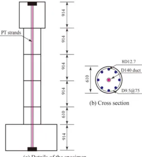
Figure 8: Model dimension diagram (unit: mm).
Figure 8 shows the design details of the modified column. The four segments are connected by the unbonded posttensioned tendon at the centre of the column. All segments contain a circular cross section with a diameter of 610 mm. The segments are confined by transverse reinforcement with a diameter of 9.5 mm and a space of 75 mm. Eight longitudinal steel bars with a diameter of 12.7 mm are placed evenly around the segments. The structure size and material properties of this model are different with the PSBC model in the third section. But the structure form and modeling method for the two models are same. Table 5 shows parts of the parameters of the two models (Model-1, Model-2).
Table 5: Part of the parameters of two models.
Model Structural style Calculated height (mm)
Shear span ratio
Section diameter
(mm)
Volume reinforcement
ratio (%)
Axial load ratio
Prestress arrangement
Model-1 USPC 1850 5.29 350 0.638 0.075 Middle
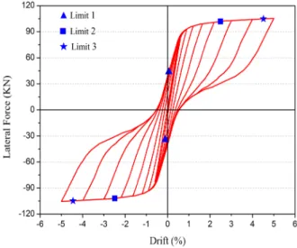
Figure 9: Lateral force-drift curve.
For this column, the shear span ratio, longitudinal reinforcement ratio, axial compression ratio and confining reinforcement ratio can be found and also can be calculated. Among them, l/d=6, ρt=0.347%, ρw=0.652%, n* 0=0.10. The upper values were introduced into the formula (5) to calculate the value of β*. The model was established and analyzed by the same modeling method. Based on the results from the calculation, the lateral force-drift curve of this column can be obtained and plotted in Figure 9.
As the constant values for this designated column presented in the damage index formula, the ultimate deformation under monotonic loading δu, the calculated yield strength Qy are obtained from the analysis of the
lateral force-drift curve. The other parameters in the DI formula (1) can be determined by the same method as performed in the above part. The only difference from the previous method is that the cyclic loading factor β* is obtained by the modified formula (5), rather than the inverse operation. Then, all the parameters values are brought into the formula (1) to get the damage index limit corresponding to each damage state, as shown in Table 6.
Table 6: The damage index and the average errors.
Damage states DI (model-1) DI (model-2) Average error (%)
Slight damage DI<0.1407 DI<0.1121 20.3%
Moderate damage 0.1407<DI<0.5391 0.1121<DI<0.4935 14.4%
Severe damage 0.5391<DI<1 0.4935<DI<0.9468 6.8%
Collapse 1<DI 0.9468<DI 5.0%
6 RESULTS AND DISCUSSIONS
Figure 9 shows the lateral force-drift curve of the verified column. The maximum residual displacement is 0.52% at 5% drift cycle, which does not reach 1%. Limit 1 is observed at 0.2% drift. Limit 2 is found at 2.48% drift during 2.5% drift. Limit 3 of the column occurs at 4.56% drift during the 5% drift. The slight damage is below the Limit 1 and the moderate damage is above the Limit 1. Likewise, the boundary of the moderate damage and the severe damage is Limit 2. Limit 3 is the point of distinction between severe damage and collapse.
Table 6 shows the damage index of the two columns and the damage index errors between the two column models. For the collapse of the column in the verification, the corresponding DI value is not 1, which is different from the value in theory. The errors could be made in the entire column analysis, which cannot be avoided completely. The error between the DI value and the standard value is 5.0%, which is within the acceptable range. The average error corresponding to slight damage between the two columns reaches to 20.3%. The average errors decrease with the increase in damage degree. The average error corresponding to moderate damage is calculated to be 14.4%. The average error for the severe damage is 6.8%.
prefabricated segmental bridge columns based on more experimental and numerical models. And the results would be more precise.
For the two columns models, the reasons for the difference of the average error between the damage index corresponding to each damage state may include many aspects. The differences in some factors can all affect the damage state. The factors could conclude the shear span ratio, longitudinal reinforcement, spacing of stirrup and initial stress of tendon. For Example, for slight damage, the average error is the largest of all errors. The reason may be that the damage difference appeared during the initial damage period for the two columns models is relatively larger than other damage states. With the increase of the damage degree, the damage of the two columns models are found to be closer to each other. Until reaching the collapse state, the damage index will be almost the same. Generally, the analysis method of the damage index of the PSBC consists of certain basis and correctness measures, which can be further applied.
7 CONCLUSIONS
This paper presented the study on the damage index of the prefabricated segmental bridge columns under cyclic loading. The finite element models of the PSBC were used for the quantitative assessment of the limit-state capacities for different damage states. The reasonable damage index formula of the PSBC was established, and the damage index was then developed based on the numerical analysis. The following conclusions can be drawn:
The proposed method for the limit-state capacities for different damage states of the PSBC consists of four parameters: the compressive strain of concrete, the tensile strain of steel, the prestress level and the residual displacement.
The reasonable damage index formula of the PSBC was derived from modifying the formula proposed by Park and Ang, based on the numerical analysis. The cyclic loading factor in the formula was modified, taking the axial stress ratio provided by the prestressed tendons into consideration. The method of obtaining the damage index formula can provide a simple strategy for the seismic analysis of the PSBC. In this paper, the maximum average error value is 20.3% between the proposed damage index and the one obtained in verification. The minimum average error value is 5%.
The proposed method of analyzing the damage index could be applied to do further study on the seismic vulnerability analysis evaluation of bridge structures with prefabricated segmental columns. In the future work, further experiments and research will be conducted to improve this method of determining the damage index for the PSBC. The seismic fragility analysis of bridges with PSBC will be also introduced.
Acknowledgements
This work was supported by the National Natural Science Foundation of China (Grant No. 51508276), the Fund of National Engineering and Research Center for Mountainous Highways (Grant No. GSGZJ-2017-02), and the Postgraduate Research & Practice Innovation Program of Jiangsu Province (Grant No. SJCX17_0117).
References
Bertsimas, D., and Frankovich, M. (2013). Air Traffic Flow Management at Airports: A Unified Optimization Approach. Proceedings of the 10th USA/Europe Air Traffic Management Research and Development Seminar. Chicago, USA.
Beydokhty, E. Z., Shariatmadar, H., Beydokhty, E. Z., and Shariatmadar, H. (2016). Behavior of Damaged Exterior RC Beam-Column Joints Strengthened by CFRP Composites. Latin American Journal of Solids & Structures, 13(5):881-897.
Billington, S. L., and Breen, J. E. (2000). Improving standard highway bridges with attention to cast-in-Place substructures. Journal of Bridge Engineering, 5(4): 344–351.
Bu, Z. Y., Ou, Y. C., and Song, J. W., Zhang, N. S., and Lee, G. C. (2016). Cyclic loading test of unbonded and bonded posttensioned precast segmental bridge columns with circular section. Journal of Bridge Engineering, 21(2).
Chou, C. C., and Chen, Y. C. (2006). Cyclic tests of post-tensioned precast CFT segmental bridge columns with unbonded strands. Earthquake Engineering and Structural Dynamics, 35 (35): 159-175.
Dawood, H., ElGawady, M. A., and Hewes, J. T. (2014). Factors affecting the seismic behavior of segmental precast bridge columns. Frontiers of Structural and Civil Engineering, 8(4): 388-398.
Guo, T., Cao, Z., and Xu, Z., and Lu, S. (2016). Cyclic load tests on selfcentering concrete pier with external dissipators and enhanced durability. Journal of Structural Engineering, 142(1): 04015088.
Hewes, J. T., and Priestley, M. N. (2002). Seismic design and performance of precast concrete segmental bridge columns Report No. SSRP-2001/25. San Diego, CA: University of California.
Hose, Y., Silva, P., and Seible, F. (2000). Development of a performance evaluation database for concrete bridge components and systems under simulated seismic loads. Earthquake Spectra, 16(2): 413-442.
Hwang, H., Jernigan, J. B., and Lin, Y. W. (2000). Evaluation of seismic damage to Memphis bridge and highway systems. Journal of Bridge Engineering, 5(4): 322-330.
Hwang, H., Liu, J. B., and Chiu, Y. H. (2001). Seismic fragility analysis of highway bridges. Referenzmodellierung.
Japan Road Association (2002). Design Specification of Highway Bridge: Part V-Seismic Design (JRA 2002, in Japan).
Karim, K. R., and Yamazaki, F. (2001). Effect of earthquake ground motions on fragility curves of highway bridge piers based on numerical simulation. Earthquake Engineering & Structural Dynamics, 30(12): 1839-1856.
Karim, K. R., and Yamazaki, F. (2010). A simplified method of fragility curves for highway bridges. Earthquake Engineering & Structural Dynamics, 32(10): 1603-1626.
Kim, D. H., Moon, D. Y., Kim, M. K., Zi, G., and Roh, H. (2015). Experimental test and seismic performance of partial precast concrete segmental bridge column with cast-in-place base. Engineering Structures, 100: 178-188.
Liu, Y. H. (2008). Research on urban viaduct seismic behaviors in perforcement-based seismic design theory. Southwest Jiaotong University. (in Chinese).
Mazzoni, S., MCBCkenna, F., and Fenves, G. L. (2001). Opensees command language manual.
Ministry of Transport of the People's Republic of China – MOT (2004). Code for Design of Highway Reinforced Concrete and Prestressed Concrete Bridge and Culverts(JTG D62-2004, in Chinese).
Ministry of Transport of the People's Republic of China – MOT (2008). Guidelines for Seismic Design of Highway Bridges(JTG/T B02-01-2008, in Chinese).
Motaref, S., Saiidi M S, and Sanders, D. (2014). Shake table studies of energy-dissipating segmental bridge columns. Journal of Bridge Engineering, 19(2): 186-199.
Nielson, B. G., Desroches, R. (2012). Analytical seismic fragility curves for typical bridges in the central and southeastern united states. Earthquake Spectra, 23(3): 615–633.
Ou, Y. C., Wang, P. H., Tsai, M. S., Chang, K. C., and Lee, G. C. (2010). Large-scale experimental study of precast segmental unbonded posttensioned concrete bridge columns for seismic regions. Journal of Structural Engineering, 136(3): 255-264.
Panagiotou, M., Trono, W., Jen, G., Schoettler, M., and Ostertag, C. P. (2015). Seismic response of a damage-resistant recentering posttensioned HYFRC bridge column. Journal of Bridge Engineering, 20(7): 04014096.
Park, Y. J., and Ang, H. S. (1985). Mechanistic seismic damage model for reinforced concrete. Journal of Structural Engineering, 111(4): 722-739.
Rojahn, C., Mayes, R., and Anderson, D. G. (1997). Seismic design criteria for bridge and other highway structures. National Center for Earthquake Engineering Research.
Stone, W. C., Taylor, A. W. (1993). Seismic performance of circular bridge columns designed in accordance with AASHTO/CALTRANS standards. Concrete Bridge, (170).
Wang, Z. Q., Ge, J. P., and Wei, H. Y. (2014). Seismic performance of precast hollow bridge piers with different construction details. Frontiers of Structural and Civil Engineering, 8(4): 399-413.
Wang, Z., Wang, J. Q. (2016). Review of seismic performance of prestressed segmental precast and assembled piers. Journal of Architecture and Civil Engineering, 33(6): 88-97.
Zhang, Y., and Zhai, Y. (2018). Improvements in seismic performance of prefabricated bridge piers. Journal of Highway and Transportation Research and Development. (English Ed), 12(2): 43-50.
Zhang, Y., and Dias-da-Costa, D. (2017). Seismic vulnerability of multi-span continuous girder bridges with steel fibre reinforced concrete columns. Engineering Structures, 150: 451-464.