USING THE ANSYS FLUENT FOR SIMULATION OF TWO-SIDED LID-DRIVEN FLOW IN A STAGGERED CAVITY
Jelena Đ. Marković*, Nataša Lj. Lukić, Jelena D. Ilić, Branislava G. Nikolovski, Milan N. Sovilj and Ivana M. Šijački
University of Novi Sad, Faculty of Technology, Bulevar Cara Lazara 1, 21000 Novi Sad, Serbia This paper is concerned withnumerical study of the two-sided lid-driven fluid flow in a staggered cavity. The ANSYS FLUENT commercial software was used for the simulation, In one of the simulated cases the lids are moving in opposite directions (antiparallel motion) and in the other they move in the same direction (parallel motion). Calculation results for various Re numbers are presented in the form of flow patterns and velocity profiles along the central lines of the cavity. The results are compared with the existing data from the literature. In general, a good agreement is found, especially in the antiparallel motion, while in the parallel motion the same flow pattern is found, but the velocity profiles are slightly different.
KEY WORDS: cavity benchmark; fluid flow; two-sided lid driven cavity; parallel mo-tion; antiparallel motion
INTRODUCTION
In the past decades, flow in a lid-driven cavity has been studied extensively as one of the most popular fluid problems in the computational fluid dynamics (CFD). This classical problem has attracted considerable attention because the flow configuration is relevant to a number of industrial applications. ANSYS FLUENT uses conventional algorithms for calculation of macroscopic variables. Computational advantages of this commercial software are simplicity of the problem setup, parallel computing and higher precision.
Two-sided lid-driven staggered cavity appears to be a synthesis of two benchmark problems: a lid-driven cavity and backward facing step. Furthermore, it has all the main features of a complex geometry. Nonrectangular two-sided lid-driven cavities have been recently introduced and investigated as a potential benchmark problem by Zhou et al. (1), Nithiearasu and Liu (2) and Tekic et al. (3). Zhou et al. Presented a solution for the flow in a staggered cavity obtained by using wavelet-based discrete singular convolution. Nithiarasu and Liu solved the same problem using the artificial compressibility-based
APTEFF, 43, 1-342 (2012) UDK: 532.54:66.011:004.4
DOI: 10.2298/APT1243169M BIBLID: 1450-7188 (2012) 43, 169-178 Original scientific paper
characteristic-based split scheme. Tekic et al. solved this problem by using the lattice-Boltzmann method. The aim of this work was to study two-sided lid-driven staggered cavity utilizing the commercial software package FLUENT. Solutions are presented in the parallel and antiparallel motion of the lid and the flow pattern which develops under these conditions.
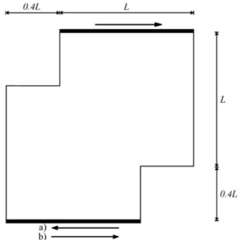
Figure 1. Schematic diagram of two-sided lid-driven staggered cavity: (a) antiparallel; (b) parallel motion.
MATHEMATICAL FORMULATION
General Scalar Transport Equation: Discretization and Solution -ANSYS FLU-ENT uses a control-volume-based technique to convert a general scalar transport equa-tion to an algebraic equaequa-tion that can be solved numerically. This control volume techni-que consists of the integration of the transport equation about each control volume, yiel-ding a discrete equation that expresses the conservation law on a control-volume basis.
Discretization of the governing equations can be illustrated most easily by considering the unsteady conservation equation for transport of a scalar quantity Φ. This is demon-strated by the following equation written in integral form for an arbitrary control volume
V as follows:
V V
dV S A d A
d v dV
t
[1]
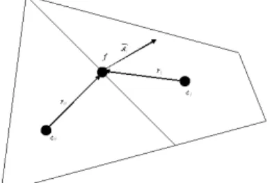
where ρ is the density, v - velocity vector; A - surface area vector; - diffusion coefficient for Φ, S source of Φ per unit volume. Equation [1] is applied to each control volume, or cell, in the computational domain. The two-dimensional, triangular cell shown in Figure 1 is an example of such a control volume. Discretization of Equation [1] on a given cell yield
Nfaces faces
f
N
f
f f f
f f
fv A A SV
V
t
where Nfacesrepresents the number of faces enclosing the cell, Φf is the value of
con-vected through the face f, Af is the area of the face f and V is the cell volume.
The equations solved by ANSYS FLUENT take the same general form as the one given above and apply readily to multi-dimensional, unstructured meshes composed of arbitrary polyhedra.
Figure 2. Control volume used to illustrate discretization of a scalar transport equation. For relatively uncomplicated problems (laminar flows with no additional models acti-vated) in which convergence is limited by the pressure-velocity coupling, a converged so-lution can often be obtained more quickly using SIMPLEC. With SIMPLEC, the pres-sure-correction under-relaxation factor is generally set to 1.0, which aids in convergence speedup. In the present study, a slightly more conservative under-relaxation value was used, and it is equal to 0.7 .Special practices related to the discretization of the momen-tum and continuity equations and their solution by means of the pressure-based solver is most easily described by considering the steady-state continuity and momentum equati-ons in the integral form:
0
v dA [3]
V dV F A d A d pI A d v
v
[4]
where I is the identity matrix, is the stress tensor, and Fis the force vector.
Discretization of the Momentum Equation - previously described a discretization scheme for a scalar transport equation is also used to discretize the momentum equations.
For example, the x-momentum equation can be obtained by setting u:
S i A p u
a u a
nb
f nb nb
P
^
[5]
APTEFF, 43, 1-342 (2012) UDK: 532.54:66.011:004.4
DOI: 10.2298/APT1243169M BIBLID: 1450-7188 (2012) 43, 169-178 Original scientific paper
Therefore, an interpolation scheme is required to compute the face values of pressure from the cell values.
Discretization of continuity equation- Equation [1] may be integrated over the control volume to yield the following discrete equation
faces Nf f fA
J 0 [6]
where Jf is the mass flux through the face vn. In order to proceed further, it is necessary
to relate the face values of the velocity, vn, to the stored values of velocity at the cell
centers. Linear interpolation of cell-centered velocities to the face results in an unphysical checker-boarding of pressure. ANSYS FLUENT uses a procedure similar to that outlined by Rhie and Chow (4) to prevent checkerboarding. The face value of velocity is not ave-raged linearly; instead, momentum-weighted averaging, using weighting factors based on the aP coefficient from the equation [5], is performed. Using this procedure, the face flux,
Jf, may be written as:
) (
)) ) ( ( ) ) (
(( 1
^
1 0
, ,
, , , ,
0 1
1 0
0 1
0
1 1 0 0
c c f f c
c c
c f c
p c p
c n c p c n c p f
f d p p r p p r J d p p
a a
v a v a
J
[7]
where
0
c p ,
1
c p and
0
,c n v ,
1
,c n
v , are the pressures and normal velocities, respectively,
within the two cells on either side of the face, and J^f contains the influence of velocities
in these cells (Figure 2). The term df is a function of aP, the average of the momentum
equation of the aPcoefficients for the cells on either side of the face f.
Spatial Discretization - By default, FLUENT stores discrete values of the scalar at the cell centers (c0 and c1 in Figure 2). However, the face values fare required for the
convection terms in Equation [2] and they have to be interpolated from the cell center values. This is accomplished using an upwind scheme. Upwinding means that the face value f is derived from quantities in the cell upstream, or „upwind“, relative to the
di-rection of the normal velocity vn in Equation [2]. The diffusion terms are
central-differenced and are always second-order accurate.
When second-order accuracy is desired, the quantities at cell faces are computed using a multidimensional linear reconstruction approach (5,6). In this approach, higher-order accuracy is achieved at cell faces through a Taylor series expansion of the cell-centered solution about the cell centroid. Thus, when second-order upwinding is selected, the face value f is computed using the following expression:
r SOU
f
, [8]
where and are the cell-centered value and its gradient in the upstream cell, and r is the displacement vector from the upstream cell centroid to the face centroid. This for-mulation requires the determination of the gradient in each cell. Finally, the gradient
Si
finem 0.001 densi lid ve sired for th of m first-o used
In lid dr resuls geom result
Figu
T tours veloc Figur
imulation setup
-ment adjacent to th 1 Pas. Reynolds n ity; μ is dynamic v elocity in the x dir Re number. Boun he upper and botto moving depending order upwind sche as starting conditi
Validatio
n order to validate riven square cavi st in the available metric center of th
ts of Chen et al. (6
ure 3. Velocity pro
he results for ant at various Re nu city u – and v-pro re 5. For comparis
Mesh was created he walls. Density number was calcu visocity of the flu rection. The veloc ndary conditions w om moving lid as
on the case (par eme were taken a ions for the secon
RESULTS on or results of o
e the simulation m ity is simulated f
literature. Figure he cavity. The o 6) and Ghia et al (
ofiles u – and v- a sq
Antiparall
tiparallel motion o umbers are present
ofiles through the son sake, the resul
d with 140x140 n y of the fluid was
lated as Re = uL
uid; L is the charac city of the moving were set as no-sli moving walls wit rallel or antiparal
s 0.5 velocity of t nd-order upwind sc
AND DISCUSSI one-sided lid –dri
mehod, a popular b for different Re n
3 shows the u- an obtained results a
(7).
along the vertical a quare cavity.
lel motion of the l
of lids are listed i ted in Figure 4, w mid-section of th lts obtained by Te
number of elemen set to 1 kg/m3, a
L/. where ρ repre cteristical length o g lid was calculate ip for the left and th defined velocit llel). Starting con the moving lids, a
cheme.
ION
iven square cavit
benchmark proble numbers and com nd v-velocity prof are in good agree
and horizontal cen
lids
in Table 1. Stream while the results o
he staggered cavi ekic et al. (3) are a
nts with grid re-and viscosity to
esents the fluid of cavity, and u ed based on de-right wall, and ty and direction nditions for the
nd results were
ty
em of one-sided mpared with the file, through the ement with the
nterlines of the
mfunction con-obtained for the
APTEF DOI: 1
It comp comp stron
A behav patter more ferred cally locate
W the ex creas mary corne
Figu
V The m
FF, 43, 1-342 (2012) 10.2298/APT1243169
t is evident that w ponents also incre pared to the visco ger for higher Re. As previously men vior for Re numb rns are achieved e e precisely there ar d to as secondary aligned along the ed in the left and r
Figure 4. Streamf With the increase o xpense of the prim se of the Re numb y vortices along t ers next to the mov
ure 5. Velocity pro staggered c
Velocity profiles al most notable diff
M
with the increase i ease in magnitud ous ones. As a re .
ntioned, three stud bers above 1000. even at Re numbe re three primary v for easier compa e mid-section of th
right bottom corne
function contours
of Re, the primary mary vortex locat ber, the bottom lef he long diagonal ving lid.
ofiles u – and v- a cavity –antiparalle
long the vertical c ference is for Re
in the Re number de. Furthermore, t esult, the gradien
dies on staggered In the present stu ers lower than 100 vortices, although arison of the result he cavity. Oppose er of the cavity.
at various Re num
y vortex located in ted in the upper r ft corner vortex d l of the cavity, se
along the vertical a el motion (Rea – T
centerline of the c =100. While the
UDK: 53
BIBLID: 1450-7188 ( Origin
r, extreme values the inertial forces nts close to the m
cavity, (1)-(3) sh udy, symmetric a 00. Multiple vortic
in Table 1 the thi ts. Primary vortic ed to this, seconda
mbers – antiparall
n the left bottom c right corner. With
isappears, and the econdary vortices
and horizontal cen Tekic et al. results
cavity differ for so results of Tekic
32.54:66.011:004.4
(2012) 43, 169-178 nal scientific paper
of the velocity s are dominant moving lids are
howed unsteady and asymmetric ces are formed, ird vortex is
re-es are all verti-ary vortices are
el motion.
corner grows at h the further
in-ere are two pri-s appear in the
nterlines of the (3))
more more (Re= Cons of Gh previ found tions T Table vortic Tabl A comp differ It shear gular Re 50a 50b 50c 100a 100b 100c
e flattened profiles e similar to the p
1000). The veloc sidering that there
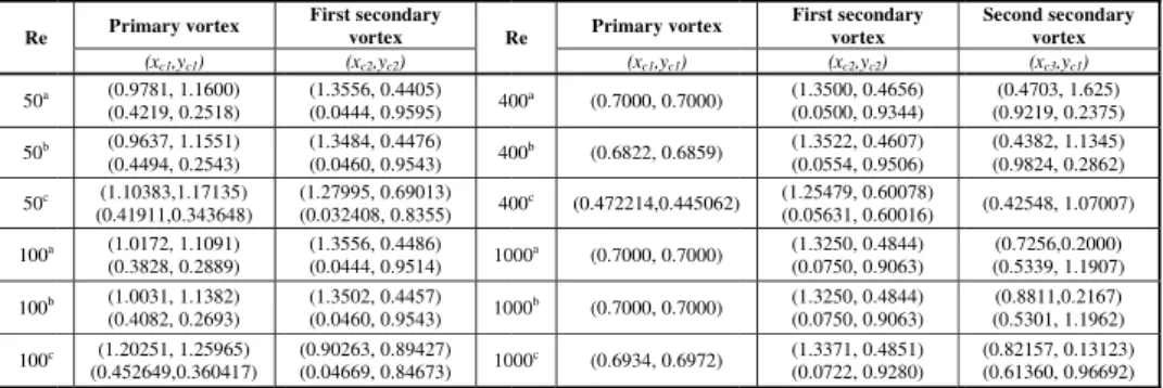
hia et al. (6) and iously mentioned d in different Re caused by the dif o summarize the e 1 and compared ces are in good ag
le 1. Locations an
As expected, paral pared to the antip rent Re numbers.
Figure 6. Stream t can be noticed th r layer forms betw r cavities, where t
Primary vortex
(xc1,yc1) (0.9781, 1.1600) (0.4219, 0.2518) (0.9637, 1.1551) (0.4494, 0.2543) (1.10383,1.17135) (0.41911,0.343648) (1.0172, 1.1091) (0.3828, 0.2889) (1.0031, 1.1382) (0.4082, 0.2693) (1.20251, 1.25965) (0.452649,0.360417)
s, ANSYS FLUEN profiles which T city profiles alon is a very good ag d Chen et al. (7), authors, the reaso number definition fferent numerical a results, the loca d with (1) and (3 greement with the
nd secondary vorti et al.(3
Par
llel motion of the parallel motion. F
mfunction contou
hat two primary co ween them. Compa the free shear laye
First secondary
vortex R
(xc2,yc2) (1.3556, 0.4405) (0.0444, 0.9595) 40 (1.3484, 0.4476) (0.0460, 0.9543) 40 (1.27995, 0.69013) (0.032408, 0.8355) 40
(1.3556, 0.4486) (0.0444, 0.9514) 10 (1.3502, 0.4457) (0.0460, 0.9543) 10 (0.90263, 0.89427) (0.04669, 0.84673) 10
NT results show th Tekic et al. (3) s
g the horizontal greement between and also between ons for disagreem
n and different bo approach.
ations of the cent 3). It can be noti results in the avai
ices – antiparallel 3), c present study
rallel motion
e opposite lids de Figure 6 shows t
urs at various Re n
ounter-rotating vo ared to the previo er is formed along Re Primary vortex
(xc1,yc1) 00a
(0.7000, 0.7000)
00b
(0.6822, 0.6859)
00c (0.472214,0.445062)
000a (0.7000, 0.7000) 000b (0.7000, 0.7000) 000c (0.6934, 0.6972)
he existence of a s showed for highe centerline are al n the present study
n results of Tekic ents with present oundary condition
ers of the vortice ced that the resu ilable literature.
motion, aZhou et
evelops a differen the streamfunctio
numbers – parallel
ortices are present ous studies of flow
g a horizontal cen First secondary
vortex
(xc2,yc2) (1.3500, 0.4656) (0.0500, 0.9344) (1.3522, 0.4607) (0.0554, 0.9506) ) (1.25479, 0.60078)
(0.05631, 0.60016) (1.3250, 0.4844) (0.0750, 0.9063) (1.3250, 0.4844) (0.0750, 0.9063) (1.3371, 0.4851) (0.0722, 0.9280) sine-like curve, er Re numbers
most identical. y and the work c et al. (3) and study could be ns
implementa-es are listed in lts for primary
al. (1), b Tekic
nt flow pattern on contours for
motion.
t and that a free w inside rectan-nterline (6), (8),
Second secondary vortex
APTEF DOI: 1 in the is no move corne streng cause show ze, so the ca body veloc with Furth incre about result Figu A profil differ horiz while les ob noun ned, the di
FF, 43, 1-342 (2012) 10.2298/APT1243169
e staggered cavity longer symmetric es towards the off er of the right wa
gth at the cost of es splitting of the wn in Figure 6. Bo o that viscous eff avity (9). As men with a constant a city profiles along the increase in th her, the free shear ase in the Re nu t the horizontal ce ts of Tekic et al., i
ure 7. Velocity pr staggered
As in the case of an les, while the pres rences occur at lo zontal centerline sh
e for the Re=100 t btained by simula ced minimum and could be a result ifferent boundary
M
y the free shear lay cal due to the upp fset. At low Re nu all and offset. A
the upper primary e primary vortex oth primary vortic fects are confined ntioned by Sahin a angular velocity a g mid sections of he Re number, ext r layer formed be umber due to turb enterline of the cav
it can be seen that
rofiles u – and v- a cavity – parallel m
ntiparallel motion sent study shows t
wer values of Re how relatively go there is a more sig ation in the presen d maximum veloc
of the different R conditions.
yer is formed alon per lid moving fro umbers, a seconda
s the Re number y vortex. At hig
and formation o ces have become m
to the thin bound and Owens (10), f at high Re numbe the cavity. As di treme velocity va etween the two pr bulence. The prof vity, as previously t the obtained prof
along the vertical motion (Rea – Tek
n, the results of Te the existence of a number (50 and od agreement for gnificant differenc nt study are more s ity pitch. These di Re calculation pr
UDK: 53
BIBLID: 1450-7188 ( Origin
ng the shorter diag om the offset, whil ary vortex is prese r increases, this v r Re numbers, se f a second secon more prominent a dary layers close fluid begins to rot rs. Figure 7 show iscussed in the pr alues also increase rimary vortices sh files confirm asym
y mentioned. Com files are quite sim
an horizontal cen kic et al. results (3
ekic et al. (3) give a minimum veloci 100). Velocity pro the Re values 50, ce. In general, the symmetrical and h ifferences, as prev rocedure, and imp
32.54:66.011:004.4
(2012) 43, 169-178 nal scientific paper
gonal. The flow le the lower lid ent close to the vortex gains in condary vortex ndary vortex as and larger in
si-to the walls of tate like a rigid ws the u- and v
-revious section, e in magnitude. hrinks with the mmetrical flow mpared with the milar.
nterlines of the 3)).
more flattened ity pitch. These ofiles along the , 400 and 1000, e velocity
CONCLUSION
Results of the ANSYS FLUENT commercial software simulation of two-sided lid-driven flow inside a staggered cavity are presented in this article. Both antiparallel and parallel motions of two facing lids are investigated. The benchmark results obtained with ANSYS FLUENT are in good agreement with the results available in the literature.
For antiparallel motion of lids in a staggered cavity results show symmetrical and asy-mmetrical flow patterns. Velocity profiles along the horizontal centerline are in a good agreement with existing data from the literature, while the profiles along the vertical cen-terline are slightly different from those used for comparison, especially for Re=50 and Re=100. These differences could be explained by the different Re calculation procedures and different boundary conditions implementation methods, considering the different numerical approach. The situation is quite similar in case of parallel motion of lids. Un-like for antiparallel motion, steady-state asymmetric patterns are obtained for all investi-gated Re numbers. It can be noticed that a free shear layer is formed along the short dia-gonal of the staggered cavity. All the main features of the flow are shown, streamline contours, horizontal and vertical velocity components along the mid sections of the cavity are visually presented, while the location of vortices is presented in Table 1.
Acknowledgement
This research was financially supported by the Ministry of Science and Technological Development of the Republic of Serbia (Project No. 46010)
REFERENCES
1. Zhou, Y.C., Patnaik, B.S.V., Wan, D.C., and Wei, G.W.: Dsc Solution for Fow in a
Staggered Double Lid Driven Cavity. Int. J. Num. Meth. Eng. 57 (2003) 211-234.
2. Nithiarasu, P. and Liu, C.-B.: Steady and Unsteady Incompressible Flow in a Double Driven Cavity Using the Artificial Compressibility (Ac)-Based Characteristic-Based
Split (Cbs) Scheme. Int. J. Num. Meth. Eng. 63 (2005) 380-397.
3. Tekić, P., Rađenović, J., Lukić, N., and Popovic, S.: Lattice Boltzmann Simulation of
Two-Sided Lid-Driven Flow in a Staggered Cavity. Int. J. Comp. Fluid Dyn. 24
(2010) 383-390.
4. Rhie, C.M. and Chow, W.L.: Numerical Study of the Turbulent Flow Past an Airfoil
with Trailing Edge Separation, AIAA 21 (1983) 1525-1532.
5. Barth, J. and Jespersen, D.: The Design and Application of Upwind Schemes on Un-structured Meshes, AIAA-89-0366, AIAA 27th Aerospace Sciences Meeting, Reno, Nevada, (1989) 10-13
6. Chen, S., Tolke, J., and Krafczyk, M.: A New Method for the Numerical Solution of
Vorticity-Streamfunction Formulations. Comp. Meth. Applied Mech. Eng., 198
APTEFF, 43, 1-342 (2012) UDK: 532.54:66.011:004.4
DOI: 10.2298/APT1243169M BIBLID: 1450-7188 (2012) 43, 169-178 Original scientific paper
7. Ghia, U., Ghia, K.N., and Shin, C.T.: High-Re Solutions for Incompressible Flow
Using the Navier–Stokes Equations and a Multigrid Method. J. Comput. Phys. 48
(1982) 387-411.
8. Perumal, D.A. and Dass, A.K.: Simulation of Flow in Two-Sided Lid-Driven Square Cavities by the Lattice Boltzmann Method, Advances in fluid mechanics VII. Boston, MA: WIT Press (2008) 45-54.
9. Patil, D.V., Lakshmisha, K.N., and Rogg, B.: Lattice Boltzmann Simulation of
Lid-Driven Flow in Deep Cavities, Comput. Fluids 35 (2006) 1116-1125.
10. Sahin, M. and Owens, R.G.: A Novel Fully Implicit Finite Volume Method Applied to the Lid-Driven Cavity Problem – Part I: High Reynolds Number Flow Calculati-ons., Int. J. Numer. Methods Fluids 42 (2003) 57-77.
Ђ
ANSYS FLUENT
Ђ. , . , . , . ,
. .
, , 1, 21000 ,
.
-ANSYS FLUENT ђ
-. ђ , –
( ) –
.
.
ђ .
,
. ,
, .
: , Ansys Fluent, , ђ