AbstrAct: In order to study stealth strike-ighter, an analysis on stealth-aerodynamic integration and conceptual design is conducted. A conceptual 3-D digital model with internal antiship missiles and air-to-air missiles is designed in CATIA software. Based on the physical optics and equivalent electromagnetic current methods, using the self-programmed RCSAnsys software, the Radar Cross Section (RCS) characteristics and characteristics of scattering intensity distribution of the model are numerically simulated. Based on the turbulence theory of standard k-ε equations, using Fluent software, the pressure, velocity and lift-to-drag characteristics of the conceptual aircraft are numerically simulated. The simulation results show that the stealth and aerodynamic characteristics of the conceptual aircraft can be designed through integration analysis process, which can provide technical support to the design of the advanced operational aircrafts.
Keywords: Conceptual design, Stealth, Strike-ighter, Computational luid dynamics, Simulation.
Integration Analysis of Conceptual Design
and Stealth-Aerodynamic Characteristics
of Combat Aircraft
Cheng Liangliang1,3, Yue Kuizhi1,2, Guo Weigang2, Yu Dazhao2
INTRODUCTION
Stealth operational aircraft is one of the trends of the development of modern military aircrafts. Depending on the stealth characteristics of the aircrat, the radar detection probability is reduced, aircrat survivability is enhanced and then the operational function is improved. For that reason, stealth operational aircrats are under vigorous research and development, such as B-2 (Scott 2006), F-22 (Anonymous 2009), F-35 (Starosta 2013), X-45 (Wise and Lavretsky 2011)and X-47 (Zhang et al. 2009) of the USA, stealth T-50 of Russia etc.
Stealth aircrat has been studied throughly by researchers at home and abroad in several respects. Many academic results have been achieved in aircrat conceptual design, the Radar Cross Section (RCS) algorithm and stealth-aerodynamic analysis etc. In Deng and Yu (2013), the conceptual coniguration parameters of all-wing aircrats are discussed. In Yue et al. (2014a), the inluence of
symmetrical incline of double-vertical ins on RCS characteristics is studied based on the physical optics method. In Yue et al. (2014b),
the RCS characteristics of the aircrat are numerically simulated based on the physical optics and equivalent electromagnetic current methods, and the RCS characteristics of the aircrat are analyzed comparatively between when it is armed with external weapons and with internal weapons. In Saha and Majumdar (2012), the aerodynamic characteristics of delta wing are theoretically simulated at 65° leading edge sweepback angle and a subsonic velocity. Kazuhiro (2013) discusses the application of unstructured mesh in Computer Fluid Dynamics (CFD) aviation. In Vallespin et al. (2012), the light
dynamic performances of jet trainers and Unmanned Combat Air
1.Beijing University of Aeronautics and Astronautics – School of Aeronautic Science and Engineering – Department of Airborne Vehicle – Beijing – China. 2.Naval Aeronautical and Astronautical University – Department of Airborne Vehicle Engineering – Laboratory of Aircraft – Yantai – China. 3.Naval Aviation Institute – Department of Carrier-based Engineering – Laboratory of Aviation Maintenance – Huludao – China.
Author for correspondence: Yue Kuizhi | Beijing University of Aeronautics and Astronautics – School of Aeronautic Science and Engineering – Department of Airborne Vehicle | Beijing 100191 – China | Email: [email protected]
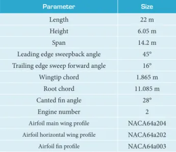
Table 1. Basic parameters of the conceptual strike-ighter.
Parameter size
Length 22 m
Height 6.05 m
Span 14.2 m
Leading edge sweepback angle 45° Trailing edge sweep forward angle 16° Wingtip chord 1.865 m
Root chord 11.085 m Canted in angle 28°
Engine number 2
Airfoil main wing proile NACA64a204 Airfoil horizontal wing proile NACA64a202 Airfoil in proile NACA64a003
Figure 2. Diagram of the aircraft with missiles. Vehicle (UCAV) are estimated using CFD method. In Peng and
Jinglong (2012), the intercoupling theory of CFD and computational structural dynamics (CSD) is applied to discuss wing flutter problem and analyze the aerodynamic and structural properties of the wings with winglets of cargo planes. He et al. (2009) studied
the numerical simulation of stealth-aerodynamic integration of lying-wing. Although several respects in the domain have been over-studied by researchers at home and abroad, certain problems still need to studied. No public academic reports on stealth strike-ighters have been obtained, and there is a lack of deep research in stealth-aerodynamic integration of conceptual aircrats.
Aiming at the issue mentioned above, this article con-ceptually designs the operational aircrat and analyzes the stealth-aerodynamic characteristics of the aircrat. It is expected that the results of the research will provide reference basis and technical support to the conceptual and stealth design of the aircrat.
concePtuAl design
he strike-ighter conceptually designed in the article is a kind of operational aircrat with a single seat, double vector engines and normal coniguration (Table 1). he layout of the conceptual strike-ighter is as follows: a pair of laperons, a pair of fore laps, a pair of moveable strake wings, canted double-vertical stabilators, a pair of diferential tailplanes, blended wing body coniguration, tricycle landing gears, a internal weapon bay, and four hardpoints under the main wings. he 3-D digital prototype of the conceptual strike-ighter is designed with CATIA sotware, including digital
prototype, a sketch map of the weapon mounting scheme and basic parameters (Fig. 1).
he weapon mounting scheme is shown in Fig. 2 as follows: (a) Scheme 1, the aircraft carries an internal long-range supersonic antiship missile and executes antiship missions; (b) Scheme 2, the aircrat carries 2 × 5 internal mid-range air-to-air missiles and executes air battle missions; (c) Scheme 3, the aircrat carries a mid-range supersonic antiship missile and ive mid-range air-to-air missiles as well as executes antiship and air battle missions.
Ater the conceptual design, the RCS characteristics and aerodynamic characteristics are numerically simulated so that the stealth-aerodynamic performance can be analyzed.
Figure 1. 3-D digital prototype.
(a) Front view (b) Side view
(c) Top view (d) Perspective view
(a) Scheme 1 (b) Scheme 2 (c) Scheme 3
THEORETICAL BASIS
he theoretical basis of stealth and aerodynamics of combat aircrat includes three parts: the testing algorithm of RCS, the theoretical basis of CFD, and the process of analysis of the stealth-aerodynamic integration.
testing Algorithm of rcs
RCS characteristics of the aircrat for it is the main characteristic in the stealth domain.
Regardless camoulage paint, when looking at the geometric proile of an aircrat, the testing algorithms for the numerical simulation of RCS characteristics are the physical optics and equivalent electromagnetic current methods. The surface element scattering is calculated by the former method, and the edge difraction is calculated by the latter (Baussard et al.
2011; Rochdi et al. 2010).
he equation of the physical optics method is:
he RCS unit conversion of the ighter is:
where: √σpo (in m2) is the RCS of a single surface element;
j is the imaginary unit and j2 = −1; k = 2π/λ is the free space
wave beam, where λ (in m) is the length of incoming radar wave; s is the surface exposed to radar;nis the unit normal vector
of object surface;er
is the unit vector at the electromagnetic
direction of receiving antenna;hi
is the unit vector of the direction of the incoming wave ield; ∙ is the dot product; × is the cross product;ris the vector from local origin to surface
unit dS;iis the unit vector of the incoming direction;sis
the unit vector of scattering direction.
he equation of equivalent current method is:
where: √σecm(in m2) is the RCS of a single edge;
t
is thetangential unit vector of the edge; q is the angle between incoming
wavesiand
t
; i oE (in V/m) is the intensity of incoming electric ield; f and g are Uimtsev difraction coeicients; Z0 (in Ω) is
the impedance of vacuum wave; i o
H (in A/m) is the incoming magnetic ield intensity;rt
is the middle-position vector of the
edge;lis the edge vector.
he RCS of the strike-ighter is the total of the RCS of n
surface units and m edges. he superposition equation is:
he arithmetic mean value of RCS of the ighter is:
where: σ (in m2) is the RCS of the ighter; σ is the RCS
arithmetic mean; σdBsm (in dBsm) is the RCS of the ighter.
theoreticAl bAsis of cfd
he turbulence numerical simulation theory of the conceptual strike-ighter adopts the standard k-ε equations, which are:
where: ρ is luid density; k is the turbulent kinetic energy; t is the time; ui is the speed per time; μ is the viscosity of luid
power; μt is the turbulent viscosity; σk is the Prandtl number
corresponding to the turbulent kinetic energy k; Gk is the
production of turbulent kinetic energy caused by the average velocity gradient; Gb is the production caused by the buoyancy
of the turbulent kinetic energy; ε is the turbulent dissipation rate; YM is the contribution to the expansion of pulsation in the
turbulence; Sk is the source term deined by users; σε means
the Prandtl number corresponding to dissipation rate; C1ε, C2ε and C3ε are the empirical constants; Sk is the source term
deined by users.
he RANS method is applied to solve the turbulent low problem.
he standard k-ε model is applied to turbulence model with high Reynolds number (Re) values while the wall-function method is adopted to solve the model with low Re values.
he wall-function method which contains a set of semi-empirical formulae is used to reine the near-wall region.
u+ = 1/k ln(Ey+) and y+ = Δy
p(Cμ
1/4k
p
1/2)/μ are derived, where
y+ > 11.63 on the control node near the wall.
u+ = y+ and y+ = Δy/v √τ
w/ρare derived, where y
+ < 11.63
on the control node near the wall. (1)
(5)
(6)
(7) (4)
(2)
(3)
where: y+ is a non-dimensional parameter and y+ = Δyρu
τ /μ ;
Δy is the distance to the wall; uτ = (τw/p)1/2 is the wall friction
velocity and τw is the wall shear stress; u+ is a non-dimensional
parameter and u+ = u/u
τ ; u is the mean velocity of the luid;
E is the energy of the luid; Δyp is the distance from node p
to the wall; Cμ is an empirical constant and kp is the kinetic
energy of node p.
the AnAlysis Process of the steAlth-AerodynAmic integrAtion
The main steps for analysis of the stealth-aerodynamic integration are as follows. A 3-D model of the aircraft is built in CATIA software; (2) with the self-compiled software named RCSAnsys, the RCS of the model is numerically simulated based on physical optics and equivalent electromagnetic current methods; (3) the CFD numerical simulation of the model is conducted with Fluent software; (4) the performances of stealth-aerodynamic integration of the model will be analyzed comprehensively. The model of the aircraft should be improved or rebuilt until the results meet the demands.
Ater the theoretical basis is obtained, the analysis and simulation are conducted as follows.
RESULTS AND DISCUSSION
There are two parts in this section: the results and discussion of RCS and the results and discussion of CFD.
rcs
Based on the physical optics and equivalent electromagnetic current methods, it was used the self-programmed RCSAnsys
sotware to make numerical simulation on the RCS character-istics of the 3-D digital prototype.
he RCS numerical simulation method applied in the paper is an approximate method for cavity calculation, and the exact solution for the inlets and nozzles cannot be obtained. he engines that have not been exposed to radar wave directly for the inlets are closed with inclined protective screening. he inlets of the model are also sealed with inclined planes for the calculation of RCS. he nozzles of the model are closed with cones and annuluses for calculation.
he conditions for the simulation in this paper are: two ways of polarization: H-H and V-V polarization; three pitch angles of incoming radar waves: −5°, 0° and +5°; four frequency bands: L, S, C and X. With Eqs. 1 to 5, the RCS of the plane is numerically simulated and the RCS characteristic curves of 24 planes and 8,640 pictures of RCS scattering feature are obtained.
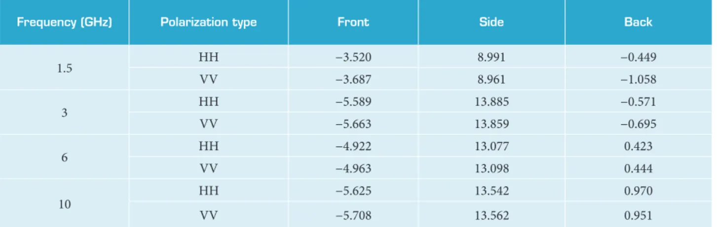
Under H-H polarization and 0° pitch angle, RCS characteristic curves of frequencies equal to 1.5, 3, 6 and 10 Hz are numerically simulated, as shown in Fig. 3. he RCS mean characteristics are simulated and shown in Tables 2–4. he RCS scattering characteristics of various parts of the plane are obtained, as shown in Fig. 4.
On the one hand, the RCS value of the model in speciic direction can be as low as −40 dBsm, which is a very low value shown in Fig. 3 and Tables 2–4; on the other hand, the relatively higher RCS value can be obtained in certain forward angle range of the model. he mean RCS value in a range of ± 30° of the forward direction is −5.625 dBsm when exposed to 10-GHz radar wave. In general, it is the same or even exceeds the stealth level of modern ighters in the world.
The distribution of RCS scattering characteristics of the conceptual strike-fighter is shown in Fig. 4: (a) in the
Table 2. Pitch angle of −5 ° and azimuth range of ± 30° — RCS mean value (in dBsm).
frequency (ghz) Polarization type front side back
1.5 HH −4.040 15.220 −1.834
VV −3.971 15.214 −1.839
3 HH −4.657 18.598 −1.679
VV −3.971 15.214 −1.839
6 HH −2.585 16.492 −0.580
VV −2.583 16.484 −0.585
10 HH −4.943 14.611 −0.927
forward direction, RCS intensity distribution is fairly high on the engine in the air inlet, so there should be measures taken in the entrance of the inlet to reduce the intensity on the engine; (b) in both sides, the RCS intensity in the
Figure 3. RCS characteristic curves (H-H polarization, pitch angle = 0°).
-30 -20 -100 10 20
30 0 30
60
90
120
150 180
210 240 270
300 330
-30 -20 -10 0 10 20 30
σdB
sm
/dB
s
m
1.5 GHz 3 GHz 6 GHz 10 GHz
Table 3. Pitch angle of 0° and azimuth range of ± 30° — RCS mean value (in dBsm).
frequency (ghz) Polarization type front side back
1.5 HH −6.056 13.070 −1.374
VV −6.197 13.102 −1.496
3 HH −4.596 15.010 −1.735
VV −4.615 15.010 −1.796
6 HH −7.991 15.248 −0.224
VV −8.021 15.238 −0.196
10 HH −7.982 14.737 −0.140
VV −8.003 14.737 −0.133
Table 4. Pitch angle of 5° and azimuth range of ± 30° — RCS mean value (in dBsm).
frequency (ghz) Polarization type front side back
1.5 HH −3.520 8.991 −0.449
VV −3.687 8.961 −1.058
3 HH −5.589 13.885 −0.571
VV −5.663 13.859 −0.695
6 HH −4.922 13.077 0.423
VV −4.963 13.098 0.444
10 HH −5.625 13.542 0.970
VV −5.708 13.562 0.951
nose, the body, the air inlet and the tail cone is high; (c) in the backward side, the intensity of the engine is high; (d) under 0° pitch angle of the incoming radar wave and 10° azimuth, the intensity in the front edge of the strake wings and canopies is relatively high; (e) under −5° pitch angle of the incoming radar wave and 170° azimuth, the RCS intensity in the jet nozzle of the engine and in the tail is high; (f) under 10° pitch angle of incoming radar wave and 75° azimuth, the intensity in nose, middle body, tail cone, the air inlet and vertical tailsis high and measures should be taken to reduce the intensity.
The numerical simulation of RCS characteristics can be used to calculate the RCS of each component of a plane and understand the RCS scattering characteristics there. It is signifi- cant for the further improvement of the forms and struc-tures of the plane and reduction of its RCS intensity.
cfd
It was used ANSYS14.5 sotware and the Fluent module in the Workbench sotware so that a CFD analysis was carried out on the conceptual strike-ighter, which mainly includes the following several parts: mesh generation, CFD numerical simulation and lit-drag characteristics analysis.
Mesh Generation
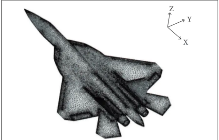
An analysis of the luid mechanics of the strike-ighter is done. First, the 3-D digital prototype of the plane space is closed. hen we import the Workbench module in the Fluent sotware. In the Geometry, submodule generates geometric form of the strike-ighter. hen the geometric form is placed on the low ield; then, in the Mesh module, the mesh is generated. he region near the wall is reined with unstructured tetrahedron grid.
he speciic processing of the wall function is as follows: the velocity values present a linear distribution along the normal direction of the wall where y+ < 11.63 for the corresponding
layer is the viscous sublayer. In this case, u+ = y+.
he log-law distribution of velocity is observed on normal direction of the wall where 11.63 < y+ < 300 for the low is in
log-law layer and u+ =1/к ln y+ + B = 1/к ln(Ey+), where к is
Karman constant, B and E are constants connected with surface
roughness and к = 0.4, B = 5.5 and E = 9.8 for smooth surface.
A non-structural mesh of the plane is generated in Mesh module, shown in Fig. 5. he number of grids of the plane in the low ield is 39,686,281.
CFD Numerical Simulation and Lift-Drag Characteristics Analysis
In this section, using Fluent module in Workbench sotware, the aerodynamic characteristics of the conceptual strike-ighter are numerically simulated. Turbulence numerical simulation theory of the plane uses the standard k-ε equation. As the
velocity is 270 m/s and air low has signiicant compressibility, the density-based solver is adopted.
Using Fluent sotware, setting the pressure of the incoming low at 101,325 Pa, when the coming low angle is 0°, CFD numerical simulation obtains: pressure distribution on the conceptual strike-ighter surface, as shown in Fig. 6; velocity distribution of low ield of the conceptual strike-ighter, as shown in Fig. 7.
(a) X-band (pitch angle = 0°; azimuth = 0°)
(b) X-band (pitch angle = 0°; azimuth = 90°)
(c) X-band (pitch angle = 0°; azimuth = 180°)
(d) C-band (pitch angle = 0°; azimuth = 10°)
(e) S-band (pitch angle = −5°; azimuth = 170°)
(f) L-band (pitch angle = 10°; azimuth = 75°)
Figure 4. RCS scattering properties of aircraft components.
Y
X Z
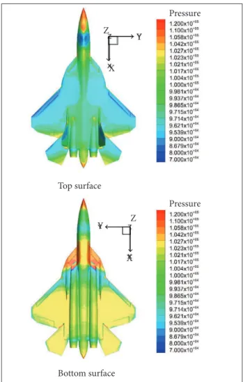
X Velocity Figure 6. Pressure distribution of the conceptual strike-ighter.
plane nose pressure is strong and radome frontal pressure is greater than 1.2 × 10⁵ Pa; pressure on the aircraft canopy
and on the wing leading edge is smaller, and the minimum is 8.679 × 10⁴ Pa; the greatest pressure is on the horizontal
tail wing surface, near the 9.714 × 10⁴ Pa; the tail cone rear
pressure is strong, where the maximum pressure is about 1.2 × 10⁵ Pa.
It is known from Fig. 6b that: the bottom surface of the plane is under higher pressure; the pressure on the bottom surface is higher than that on the top surface of the forward part of the plane body, the effect of which provides a lift for the plane; on the fuselage, bottom surface and the top surface have similar pressure. The bottom surface of the middle part contributes with a small part to the lift force; on the backward fuselage, the bottom surface is under stronger pressure than on the top surface, about 1.021 × 10⁵ Pa, and the bottom surface of
backward body has a contribution to the lift; the wings, flat tail and moving strake wings are under stronger pressure on the bottom surface than on the top surface pressure, and the lower pressure is about 1.027 × 10⁵ Pa. The wings,
flat tail and movable strake wings all contribute to the lift force.
Under the coming flow velocity of 270 m/s and the pitch angle of 0°, in x-y plane, the aircraft and its surrounding air flow field velocity distribution is shown in Fig. 7: in x-y plane, the incoming wave velocity is axisymmetric along x axis; the front of the nose, movable strake wings and main wings have a small flow speed, the minimum of which is less than 200 m/s; air flow is slow behind the rear fuselage and the back of wings, and flow separation phenomenon is observed. Low speed air flow area is longer than the others; on both sides of the nose cockpit and airplane wing tips, the air velocity is larger, and in some parts it is more than 290 m/s.
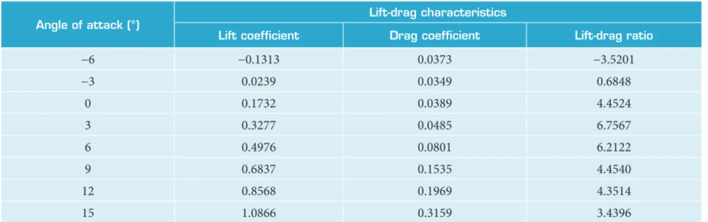
The distribution of pressure and velocity of the case as well as the lift-drag characteristics of the aircraft are obtained through CFD numerical simulation in Fluent software under the following conditions: the pressure of incoming flow from the distant flow field is 101,325 Pa, the incoming flow velocity is 270 m/s and the pitch angle is in a range of −6° to +15°. The simulation results are shown in Table 5.
A total of eight simulations are conducted in Fluent software with angles of attack at −6°, −3°, 0°, 3°, 6°, 9°, 12° and 15°, respectively, to obtain the lift and drag coefficients Figure 7. Flow ield velocity distribution of the conceptual
strike-ighter.
Pressure
Pressure Z
Z Y
Y X
X Top surface
Bottom surface
and lift-drag ratios. The CFD simulation converges after about 6,000 steps of calculation; then the convergence property of the simulations is verified and the results at different angles of attack are also obtained.
A CFD numerical simulation of the aerodynamic characteristics of the plane cannot obtain the distribution of pressure and velocity of the plane as well as analyze the lit-drag characteristics so as to evaluate aerodynamic designs of the conceptual aircrat.
he integrated design and analysis of stealth and aerodynamics are embodied in the process of parametric variation study. he parameters are changing until they meet the design requirements. he satisied parameters are obtained through iterating in integrated analysis and the process of analysis on stealth-aerodynamic integration is presented in this paper.
CONCLUSION
In the present research, the advanced combat aircrat is conceptually designed, and its stealth-aerodynamic characteristics are analyzed, reaching the following conclusions:
Angle of attack (°)
lift-drag characteristics
lift coeficient drag coeficient lift-drag ratio
−6 −0.1313 0.0373 −3.5201
−3 0.0239 0.0349 0.6848
0 0.1732 0.0389 4.4524
3 0.3277 0.0485 6.7567
6 0.4976 0.0801 6.2122
9 0.6837 0.1535 4.4540
12 0.8568 0.1969 4.3514
15 1.0866 0.3159 3.4396
Table 5. Lift-drag characteristics.
• The design and analysis of the stealth-aerodynamic characteristics of the conceptual aircraft can be based on the analysis process of the integration of stealth aircraft conceptual design and aerodynamic analysis. • Under V-V polarization, the mean RCS of forward
± 30° part of the plane is σdBsm = −6.1497 dBsm
(frequency band in 1 to 4 GHZ), 8.021 dBsm (4 to 8 GHZ) and 8.003 dBsm (8 to 12 GHZ).
• Pressure and velocity distribution of the strike-fighter in flow field is in good condition. When the pitch angle is 3°, lift coefficient is 0.3277, drag coefficient is 0.0485 and lift-dragratio is 6.7567.
The analysis method of conceptual design and stealth-aerodynamic characteristics of the combat aircraft can provide theoretical basis and technical support to the conceptual and stealth design of the aircraft.
ACKNOWLEDGEMENTS
his study was supported by the Natural Science Foundation of China (51375490).
REFERENCES
Anonymous (2009) Obama pledges F-22 veto as Senate gears up for aircraft fights. Defense Dail 243(9):57-62.
Baussard A, Rochdi M, Khenchaf A (2011) PO/MEC-based bistatic scattering model for complex objects over a sea surface. Eletromagnetic Waves/Progress In Electromagnetics Research (PIER) 111:229-251.
Deng H, Yu X (2013) Coniguration optimization of subsonic blended wing body UAV conceptual design. Acta Aeronautica et Astronautica Sinica. 35(5): 1200 – 1208
Kazuhiro N (2013) Aeronautical CFD in the age of Petaflops-scale computing: from unstructured to Cartesian meshes. Eur J Mech B Fluid 40:75-86. doi: 10.1016/j.euromechflu.2013.02.005
Peng C, Jinglong H (2012) Prediction of flutter characteristics for a transport wing with wingtip devices. Aero Sci Tech 23(1):461-468. doi: 10.1016/j.ast.2011.10.005
Rochdi M, Baussard A, Khenchaf A (2010) PO/MEC-based bistatic scattering model for complex objects over a sea surface. Proceedings of the 2010 IEEE Radar Conference; Washington, USA.
Saha S, Majumdar B (2012) Flow visualization and CFD simulation on 65° delta wing at subsonic condition. Procedia Eng 38:3086-3096. doi: 10.1016/j.proeng.2012.06.359
Scott WB (2006) B-2 program lore. Aviation Week and Space Technology 164(13):60-61.
Starosta G (2013) The F-35 readies for takeoff. Air Force Mag 96(4):38-42.
Vallespin D, Badcock KJ, Da Ronch A, White MD, Perfect P, Ghoreyshi M (2012) Computational fluid dynamics framework for aerodynamic model assessment. Progr Aero Sci 52:2-18.
Wise KA, Lavretsky E (2011) Robust and adaptive control of X-45A J-UCAS: a design trade study. Proceedings of the 18th IFAC World Congress; Milano (Italy).
Yue K, Sun C, Ji J (2014a) Numerical simulation on the stealth characteristics of twin-vertical-tails for fighter. Journal of Beijing University of Aeronautics and Astronautics 40(2):160-165.
Yue K, Sun C, Liu H (2014b) Numerical simulation on the RCS of combat aircraft for mounted missile. J Syst Eng Electron 36(1): 62-67.