O
ABSTRACT
WEAR PROMOTED IN THE APICAL THIRD OF SIMULATED
CANALS AFTER INSTRUMENTATION WITH PROTAPER
UNIVERSAL SYSTEM
Kathrein Tapia da SILVA1, Renata GRAZZIOTIN-SOARES2, Orlando LIMONGI3,
Luis Eduardo Duarte IRALA4, Alexandre Azevedo SALLES4
1- Undergraduate student, Sobracursos Endodontics Clinic, Postgraduate Center in Dentistry, Porto Alegre, RS, Brazil. 2- Professor, Sobracursos Endodontics Clinic, Postgraduate Center in Dentistry, Porto Alegre, RS, Brazil.
3- DDS, MSc, Professor, Sobracursos Endodontics Clinic, Postgraduate Center in Dentistry, Porto Alegre, RS, Brazil and Professor of Endodontics, Lutheran University of Brazil, Canoas, RS, Brazil.
4- MSc, Professor, Sobracursos Endodontics Clinic: Postgraduate Center in Dentistry, Porto Alegre, RS, Brazil and Professor of Endodontics, Lutheran University of Brazil, Canoas, RS, Brazil.
Corresponding address: Profa. Renata Grazziotin Soares - Rua Bento Gonçalves, 1624 - Centro - 95020-412 - Caxias do Sul, RS - Brazil - e-mail: [email protected]
Received: April 24, 2008 - Modification: July 10, 2008 - Accepted: August 30, 2008
bjective: This study evaluated the wear in the apical third of simulate canals after preparation with ProTaper Universal Rotary System. Material and Methods: 24 sets of instruments were used in 24 simulated canals in transparent epoxy resin blocks with degree of curvature of either 20°or 40°. The canals were photographed preoperatively and after preparation of the apical stop with ProTaper F3, F4 and F5 instruments. The initial and final images were exported to Adobe Photoshop® software and superimposed to
detect the root canal wall differences (in mm) between them, in two points located 1 (A) and 5 (B) mm from the point where the working length was established. Data were subjected to analysis of variance to verify the existence of interaction among the factors: canal curvature, instrument size and curve location. Significant level was set at 5%. Results: Regardless of the location and the canal curvature, F4 and F5 instruments produced the greatest wear (p<0.05). Conclusions: There was a deviation from the original pathway towards the outside of the root curvature in both analyzed points. All instruments produced canal transportation, but the F4 and F5 instruments produced more than the other instruments, and should thus be used with care in curved canals.
Key words: Canal transportation. Curved root canal. ProTaper Universal System. Rotary instruments. Wear.
INTRODUCTION
Root canal preparation is considered satisfactory when adequate disinfection is obtained. In addition to disinfection, it is important to maintain the continuous tapered shape development of the root canal with the largest diameter in the cervical third. Curved canals pose additional difficulties to endodontic treatment success, such as the maintenance of the original canal shape and the position of the apical foremen. Such difficulties may be attributed to limitations of the endodontic instruments, which may be unable to adapt to the anatomical variations of the root canal system1-3,27.
The introduction of nickel-titanium (Ni-Ti) rotary instruments has allowed obtaining less canal transportation and more centered preparations6,7. The Ni-Ti alloy is
superelastic, that is, by curving the instrument it misshapes and comes back to its original position when the load is removed. In curved canals, Ni-Ti instruments adapt easily to canal anatomy at the same time that they return almost all
the force needed bend them to the canal walls3,19.
The root canal system needs to be sufficiently enlarged to allow for removal of debris and microorganisms. It has been shown that apical third preparation with large-sized instruments allows that the irrigating chemical solution reaches this region and has a more effective action. Several authors15,21,22 have demonstrated that when apical preparation
is done with size 40 and 45 files there is a significantly greater reduction of the bacterial content from infected canals compared to the use of smaller size instruments. However, the incidence of canal transportation may become more evident when instrument size increases4,8.
Wear and canal morphology after instrumentation has been widely investigated in the root canals of extracted teeth and simulated canals prepared in resin blocks9,11,14.
Griffiths, et al.9 analyzed superimposed images of
aspect of the curve. The prevalence and severity of wear increased proportionally to the increase of the size of the instruments used to prepare the apical stop.
Miranzi, et al.14compared the alterations occurred in
simulated canals with 30o of curvature after preparation with
stainless steel and nickel-titanium instruments. The authors evaluated the canal wear in three levels: 2, 4 and 11 mm from the simulated canal apical termination by the superimposition of digital images using computer software. At 2 and 4 mm, there was greater wear towards the outside of the curve when stainless steel instruments were used. The stainless steel instruments also promoted greater wear at 11 mm towards the inner side of the curve. The authors concluded that both types of instruments formed the same areas of wear: towards the outer aspect of the curve in the apical third and to inside the curve in the third middle from the simulated canal.
Javaheri and Javaheri11 observed the occurrence of canal
transportation and changes in the curvature of mesiobuccal canals from extracted molars after instrumentation with the rotary systems ProTaper Universal, Hero 642 and RaCe. Apical preparation was performed up to a 30 instrument in the three systems. Using a radiographic platform, the authors radiographed the tooth with a stainless steel file inserted in the canal, before and after preparation, and superimposed the two radiographs in the computer. Statistically significant difference in canal transportation was found in the ProTaper Universal group. The authors suggested that the ProTaper Universal System may be implemented in canals with curvatures of 25 to 35o in combination with other systems
with greater flexibility and less taper, such as RaCe. Since the apical third of curved canals is the most challenging area for instrumentation, undesirable morphological alterations in this region are common. This study aimed to evaluate the wear promoted by the ProTaper Universal System in the apical third of simulated curved root canals and to determine whether the use of the complete set of instruments for apical stop preparation create inappropriate canal shape because of the increased stiffness of instruments with larger diamaters.
MATERIAL AND METHODS
Twenty-four ProTaper Universal System (Dentsply/ Maillefer, Ballaigues, Switzerland) instrument sets, each set containing S1, S2, F1, F2, F3, F4 and F5 instruments, were used. All instruments applied in this study were new and were autoclaved (Cristófoli, São Paulo, SP, Brazil) at 1 atm and 127°C, for 20 min before use.
Twenty-four simulated canals were prepared in clear epoxy resin blocks (Odontofix Comércio e Indústria de Materiais Odontológicos, Ribeirão Preto, SP, Brazil). Half of the canals were prepared with 20o curvature and 12 with
40o curvature, all of them presented 5 mm radius and 17
mm length (8 mm corresponded to upper straight portion and 9 mm corresponded to the final curved portion). Each instrument set was used to prepare one simulated canal.
The simulated canals were fixed in a flask with the canal curvature always turned to the operator’s right side. All clinical procedures were carried out by a single operator. Canals were prepared with the ProTaper instruments coupled to an electric engine (Endo Pro Torque; VK Driller Electrical equipments Ltda., São Paulo, SP, Brazil) at 300 rpm speed and 1 N/cm torque. Instrumentation started with S1 instrument followed by S2 instrument with a paitn brush movements against the canal walls. Subsequently, F1, F2, F3, F4 and F5 instruments were used in the same way until reaching working length (WL). All finishing instruments reached the WL. ProTaper’s manufacturer has suggested this sequence of instruments for clinical use.
The WL of the simulated canals was set at 16 mm, corresponding to a distance of 1 mm from the apical foramen. Instrument penetration was limited by the placement of a rubber stopper prior to the start of treatment and was checked during the course of the experiment.
The canal patency was permanently maintained with a size 10 stainless steel K-file (Dentsply/Maillefer), irrigation with a sodium lauryl sulfate-based detergent (Tergipol®;
Biodinâmica Química e Farmacêutica Ltda., Ibiporã, PR, Brazil), aspiration and inundation at each instrument change. The irrigating solution was flushed with a plastic syringe with an adaptor for a 27 G long anesthesia needle.
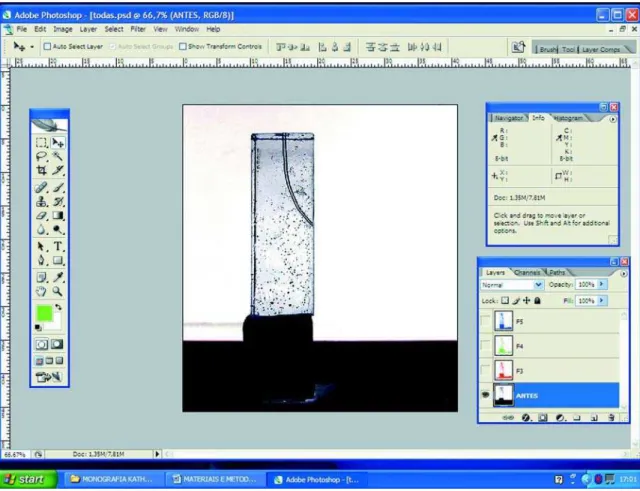
The simulated canals were positioned in a wooden photographic platform that maintained the same distance between the digital camera and the simulated canal. The canals were photographed before instrumentation and after use of the F3, F4 and F5 instruments. The images were stored in personal computer and transferred to Adobe Photoshop CS2 software version 9.0 (Adobe Systems Inc., San Jose, CA, USA). The image was converted into millimeters by associating the simulated canal original size with the image size in the computer screen. Image pixels were not reduced from the image, preserving the clearness. In Figure 1, the simulated canal image may be observed before the preparation, where gray tone inversion was applied for better visualization of canal anatomy.
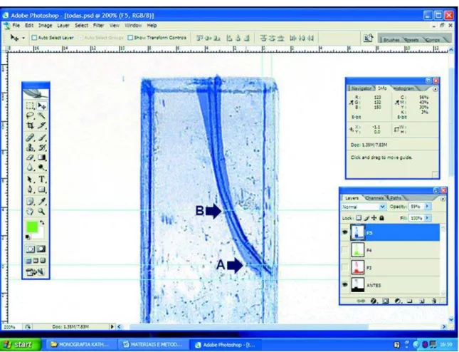
Each instrumented canal image (surgical canal) was superimposed on the non-instrumented canal image (anatomic canal). Therefore, layers were created, the image was colored, and its opaque appearance was reduced. The two images were observed by transparency, one over the other. Figure 2 presents a photograph of an instrumented canal superimposed on the photograph of a non-instrumented canal.
Later, the ruler tool was applied to locate exactly the areas in which wear would be measured in mm towards the outside of the root curvature. These locations were named A and B, which means, respective distances at 1 and 5 mm from the WL (Figure 3). Levels 1 and 5 were chosen for representing the apical third extremities.
FIGURE 1- Simulated canal before preparation with gray tone inversion in Adobe Photoshop CS2 program
RESULTS
There was no statistically significant interaction (p>0.05) among the three factors (canal curvature, instrument size and curve location). In two-by-two interactions, only the interaction between canal curvature and curve location was significant (p<0.05), which means that, independently on the instrument size, in location A, canals at 20o presented
mean wear smaller than canals at 40o, while in point B this
difference was not significant (Table 2). In Table 2, the canals with 20o curvature showed no statistically significant
difference (p>0.05) in the wear mean in relation to the location. However, in canals with 40o curvature it may be
observed that in point A, the mean wear was significantly greater (p<0.05) than in point B. As the instrument size was significant in the interactions among the factors, its main
Curvature Location Size Total
F3 F4 F5
Mean S.D. Mean S.D. Mean S.D. Mean S.D.
20o A 0.23 0.06 0.40 0.10 0.50 0.00 0.38 0.13
B 0.33 0.06 0.50 0.10 0.57 0.06 0.47 0.12
Total 0.28 0.08 0.45 0.10 0.53 0.05 0.42 0.13
40 o A 0.70 0.10 0.80 0.10 0.90 0.10 0.80 0.12
B 0.33 0.06 0.47 0.15 0.57 0.25 0.46 0.18
Total 0.52 0.21 0.63 0.22 0.73 0.25 0.63 0.23
Total A 0.47 0.27 0.60 0.24 0.70 0.23 0.59 0.25
B 0.33 0.05 0.48 0.12 0.57 0.16 0.46 0.15
Total 0.40 0.20 0.54 0.19 0.63 0.20 0.53 0.21
TABLE 1- Wear means (mm) according to instrument size, degree of curvature and curve location
FIGURE 3- Ruler tool being used to exactly locate points A and B. In this case, wear is being measured in point A, which may be observed at the right window
effect was evaluated, that is, wear (in mm). In this way, independently on the curve location and canal curvature, the instruments sizes F4 and F5 presented the greatest wear means, without statistically significant difference from each other (p>0.05). Both instrument sizes produced significantly more wear than instrument F3 (p<0.05) (Table 3).
DISCUSSION
ProTaper instruments have multiple tapers within the same shaft. Shaping files instruments (Sx, S1 and S2) have progressive taper (increase from the tip towards the handle), which adds flexibility to the middle and apical portions of the files. The Sx, S1 and S2 instruments have tip diameters of 0.19 mm, 0.17 mm and 0.20 mm respectively. On the other hand, the decreasing taper of the Finishing instruments(F1, F2 and F3 with tip diameters of 0.20 mm, 0.25 mm and 0.30 mm respectively) affords a greater mechanical resistance and rigidity to the instruments3,15,16,28.
In 2006, the manufacturer made some changes in the design of the instruments S2, F1, F2 and F3. In addition, new instruments were introduced (F4 and F5) and the system was renamed as ProTaper Universal. The S2 instrument had a mild taper modification along the blade. The tip transition angle was removed in all Finishing instruments. The cross-sectional design of instrument F3 was reduced. The changes were complemented with the release of instruments F4 and F5 with tip diameter of 0.40 mm and 0.50 mm, respectively. The overall aim of this study was to analyze the wear promoted in the apical third after endodontic preparation with the ProTaperUniversal System, in simulated root canals
under controlled laboratory conditions, in addition to determining whether the new instruments (F4 and F5) create inappropriate canal shapes.
Simulated canals were chosen in order to standardize the groups, in accordance with previous studies14,25,29.
Although simulated canals in acrylic blocks provide highly controlled in vitro conditions, such as standardized characteristics and resin hardness similar to that of root dentin, canal cross-sections differ from that of canals in extracted teeth16,26. In the present study, simulated canals
were fabricated according to Pruett et al. method with curvatures of 20 and 40o and curve radius at 5 mm19. These
curvatures, with mild and moderate degrees, were standardized as reported in previous studies2,9,25.
The apical stop was prepared up to instrument F5 in both canal types in order to produce greater wear, which is desired in teeth with pulp necrosis. In addition, it allows for a more effective canal irrigation and filling. Other authors also used instruments with larger diameter to prepare the apical stop: Peters and Barbakow17 used the Profile System
.04 until number 40 and Al-Sudani and Al-Shahrani1used
instruments with large taper (30/.06) in canals with curvature from 15 to 40o.
Wear was measured in mm from the anatomical canal wall up to the surgical canal walls. In 72 images that were superimposed on the non-instrumented canal images wear was observed (in points A and B) only outside the curve. In the inner side of the curvature, there was a superpositioning of the anatomical and surgery canal walls.
As no wear was observed in the inner side of the curvature, it is assumed that there was a canal transportation. During endodontic preparation of curved canals, the amount of wear must be similar in all walls (buccal, lingual, mesial and distal) in order to avoid the occurrence canal transportation.
Finally, it should be kept in mind that the methodology used in the present study does not provide a three-dimensional image of the canals, as obtained in studies that used computed tomography for wear analysis10,18. The
present analysis was limited to the proximal aspect, which is considered a reliable, low-cost, interesting and easy technique. Adobe Photoshop computer software allows to superpose images and affords different visualizations, reducing the opaque appearance of images23.
From the obtained results, there was significant
Curvature Location
A B
Mean Standard deviation Mean Standard deviation
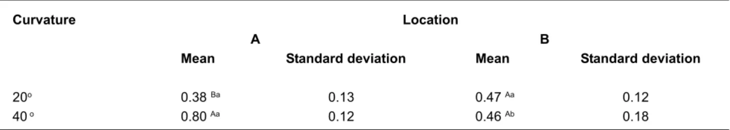
20o 0.38Ba 0.13 0.47 Aa 0.12
40 o 0.80Aa 0.12 0.46 Ab 0.18
TABLE 2- Wear means (mm) according to the curve location and the degree of canal curvature
Means followed by different uppercase letters in columns and different lowercase letters in rows differ significantly (p<0.05; ANOVA and Tukey’s test).
Size Mean (mm) Standard deviation
F3 0.40 B 0.20
F4 0.54 A 0.19
F5 0.63 A 0.20
TABLE 3- Wear means (mm) according to the instrument size
interaction between the curve location and the degree of canal curvature, which means, independently on the instrument size (F3, F4 or F5), in point A, canals of 20o
presented wear mean smaller than canals of 40o, but in point
B this difference was not significant (Table 2). Such fact has been demonstrated in a previous12 study, where M4
System was used: canals with larger curvature degree showed greater apical wear.
A possible explanation for not observing difference in the wear amount in point B, between the two canal types, was the fact that the curvature started at 8 mm from the canal entrance, becoming gradually curved from 7 mm, towards the apex. This may left the canals with similar curvature degree in point B (5 mm). The same wear values in point B were observed, after use of the instruments F3 and F5: 0.57 mm, in the canals of 20°and 40° and 0.33 mm in the canals of 20°and 40°.
In canals with 20o curvature, there was no significant
difference in the wear mean between points A and B, however in canals of 40o, the wear mean in A was larger
than in B, what may be characterized as deviation. In agreement with that, in more curved canals, there is greater wear, and for this reason, caution must be taken during instrumentation to avoid having the instrument stopped during apical preparation5,25. Canal transportation is
determined by the flexibility of the preparation instruments, the movement of the instruments in the canal, as well as the length of time the instrument is in contact with the canal wall during preparation20,24. As according to Loizides et al.13,
it is of great clinical importance when working with ProTaper Finishing files not leaving the instruments preparing the root canal for longer than 1 second when reaching the required length. This means that finishing files should be immediately removed out of the canal once the working length is achieved. In this way, shaping aberrations in the apical part of the canals can be easily minimized.
In both points A and B and regardless of the curvature degree, instruments F4 and F5 produced significantly greater wear than that produced by instrument F3, but did not differ from each other (Table 3). This occurs since, the larger metallic mass instrument quantity, the greater the resistance offered to file adaptation into the canal, because of its smaller flexibility2,3,19.
CONCLUSIONS
From the applied methodology and obtained results, it may be concluded that wear in points A and B occurred only in the outer side of the root curvature, producing canal transportation. In point A, canals with 20o curvature
presented less wear than those with 40o curvature. In point
B, this difference was not significant. In canals with 20o
curvature, there was no significant difference in the mean wear between points A and B. In canals of 40o, the mean
wear in point A was significantly greater than in point B. Independently on the location and the canal curvature, instruments F4 and F5, presented the greatest wear,
significantly greater than the wear promoted by instrument F3. All instruments produced canal transportation, but the F4 and F5 instruments produced more than the other instruments, and should thus be used with care in curved canals.
REFERENCES
1- Al-Sudani D, Al-Sharahani S. A Comparison of the canal centering ability of ProFile, K3, and RaCe nickel titanium rotary systems. J Endod. 2006;32(12):1198-201.
2- Bergmans L, Cleynenbreugel JV, Beullens M, Wevers M, Meerbeek BV, Lambrechts P. Progressive versus constant tapered shaft desing using NiTi rotary instruments. Int Endod J. 2003;36:288-95.
3- Bergmans l, Cleynenbreugel JV, Wevers M, Lambbrechts P. Mechanical root canal preparation with rotary instruments: rationale, performance and safety. Am J Dent. 2001;14(5):324-33.
4- Buchanan LS. The standardized-taper root canal preparation: part 4. GT file technique in abruptly curved canals. Int Endod J. 2001;34:250-9. 5- Calberson FLG, Deroose CAJG, Hommez GMG, De Moor, RJG. Shaping ability of Protaper nickel-titanium files in simulated resin root canals. Int Endod J. 2004;37:613-23.
6- Coleman C, Svec T. Analysis of Ni-Ti versus stainless steel Instrumentation in resin simulated canals. J Endod. 1997;23(4):232-5. 7- Coleman CL, Svec TA, Rieger MR, Suchina JA, Wang MM, Glickman GN. Analysis of Ni-Ti vs. stainless steel instrumentation by means of direct digital imaging. J Endod. 1996;22:603-7.
8- Esposito PT, Cunningham CJ. A comparison of canal preparation with nickel titanium and stainless steel instruments. J Endod. 1995;21:173-6. 9- Griffiths IT, Bryant ST, Dummer PMH. Canal shapes produced sequentially during instrumentation with Quantec LX rotary nickel-titanium instruments: a study in simulated canals. Int Endod J. 2000;33:346-54.
10- Hartmann MSM, Barletta FB, Fontanella VRC, Vanni JR. Canal transportation after root canal instrumentation: a comparative study with computed tomography. J Endod. 2007;33(8):962-5.
11- Javaheri HH, Javaheri GHA comparison of three ni-ti rotary instruments in canal transportation. J Endod. 2007;33(3):284-6. 12- Limongi O, Klymus AO, Baratto Filho F, Vanni JR, Travassos R. In vitro evaluation of the presence of canal transportation with employment of automated handpieces with continuous for root canal preparation. J Appl Oral Sci. 2004;12:195-9.
13- Loizides AL, Kakavetsos VD, Tzanetakis GN, Kontakiotis EG, Eliades G. A comparative study of the effects of two nickel–titanium preparation techniques on root canal geometry assessed by microcomputed tomography. J Endod. 2007;33(12):1455-9.
14- Miranzi BAS, Silva MM, Silva CVM, Miranzi AJS, Miranzi MAS, Vansan LP, et al. Avaliação in vitro das alterações promovidas em canais radiculares artificiais curvos após instrumentação com as técnicas ápico-cervical e cérvico-apical. J Bras Endod. 2005;5(20):349-53.
16- Patterson SS. In vivo and in vitro studies of the effect of the disodium ethylenediamine tetraacetate on human dentin and its endodontics implications. Oral Surg Oral Med Oral Pathol. 1963;16:83.
17- Peters OA, Barbakow F. Dynamic torque and apical forces of Profile .04 rotary instruments during preparation of curved canals. Int Endod J. 2002;35(4):379.
18- Peters OA, Laib A, Barbakow F, Ruegsegger P. Three-dimensional analysis of root canal geometry by high-resolution computed tomography. J Dent Res. 2000;79(6):1405-9.
19- Pruett JP, Clement DJ, Carnes DL. Cyclic fatigue testing of nickel-titanium endodontic instruments. J Endod. 1997;23(2):77-85. 20- Roane JB, Sabala CL, Duncanson JG. The balanced force concept for instrumentation of curved canals. J Endod. 1985;11:203-11.
21- Shuping G, Orstavik D, Sigurdsson A, Trope M. Reduction of intracanal bacteria using nickel-titanium rotary instrumentation and various medications. J Endod. 2000;26:751-5.
22- Sjogren US, Figdor D, Spangberg L, Sundqvist G. The antimicrobial effect of calcium hydroxide as a short-term intracanal dressing. Int Endod J. 1991;24:119-25.
23- Sonntag D, Stachniss-Carp S. Determination of root canal curvatures before and after canal preparation (part II): A method based on numeric calculus. Aust Endod J. 2006;32:16-25.
24- Tasdemir T, Aydemir H, Inan U, Unal O. Canal preparation with Hero 642 rotary Ni-Ti instruments compared with stainless steel hand K-file assessed using computed tomography. Int Endod J. 2005;38:402-8. 25- Thompson SA, Dummer PMH. Shaping ability of Hero 642 rotary nickel-titanium instruments in simulated root canals: part 2. Int Endod J. 2000;33:255-61.
26- Weine FS, Kelly RF, Bray KE. Effect of preparation with endodontic handpieces on original canal shape. J Endod. 1976;2:298-303. 27- Wildey W, Senia AS. New root canal instrument and instrumentation technique: a preliminary report. Oral surg Oral med Oral pathol. 1989;67:198-7.
28- Yared GM. Canal preparation using only one Ni-Ti rotary instrument: preliminary observations. Int Endod J. 2008;41:339-44.