*e-mail: [email protected]
Microstructure and Tribological Properties of Cobalt-based Stellite 6
Alloy Coating by Electro-Spark Deposition
QiFeng Jinga,b*, YeFa Tana
aCollege of Field Engineering, PLA University of Science & Technology, Nanjing 210007, China bUnit 78649 of PLA, Chengdu 610200, China
Received: July 19, 2012; Revised: March 5, 2013
The cobalt-based Stellite 6 coating with a thickness of 0.5 mm was deposited onto 45 carbon steel by electro-spark deposition technology. Microstructure, chemical composition, phase composition, microhardness distribution and wear resistance of the coating were researched by a series of experiments. The results indicate that, the coating with refined and compact microstructure is mainly composed of Co, Cr7C3, Co6W6C and CrCo. The coating makes metallurgical bonding interface with the substrate. Microhardness of the coating is improved significantly with an average value of 827.9 HV0.5, which is about 3.6 times that of the substrate. Under the same experimental condition, mass loss of the substrate is about 4.2-4.5 times that of the coating, so the coating shows excellent wear resistance. Main wear mechanism of the coating is abrasive wear at low speed or low load stage, and fatigue wear at high speed or heavy load condition.
Keywords: electro-spark deposition, cobalt-based alloy, coating, microstructure, wear resistance, wear mechanism
1. Introduction
A cobalt-based alloy, which containing Co, Cr, W, Mo, Ti, La etc, is a hard alloy that can resist many kinds of wear and corrosion. It also has other advantages such as high intensity, good resistance to thermal fatigue, high temperature oxidation and thermal shock. With the good thermal stability and high temperature oxidation resistance, the cobalt-based alloy is used to produce the blade of an aviation engine and gas turbine and the nozzle of a diesel engine. It is also used to make seal valve, bearing sleeve and gear by its good wear resistance and thermal shock resistance1-5. Additionally, the cobalt-based alloy is
suitable for surface strengthening and surface modification to improve the hardness, wear resistance and corrosion resistance of metal parts to extend the service life.
Electro-spark deposition (ESD) is a pulsed micro-welding process that uses short duration and high current electrical pulse to deposit electrode materials onto the metal surface with low heat input, low stress and no deformation, it is also known as electro-spark alloying (ESA). The short duration of electrical pulse produces an instantaneous high temperature of 8000-25000 °C on the electrode tip, then electrode materials are melted immediately and deposited onto the substrate surface to form a metallurgical coating based on chemical, electrochemical and electrothermal reactions6-9. The ESD technology is a
simple but an important process for surface engineering and re-manufacturing, and then tribological and mechanical properties of the metal parts can be improved effectively with low energy consumption, no pollution and no structure changes, accordingly it has been widely applied to aviation,
aerospace, nuclear, military and other fields. For example, when direct metal laser sintering tool was strengthened by ESD with tungsten carbide (WC), the service life can be extended effectively. The electro-spark process of depositing hard layer can improve the mechanical properties of the tool surface and re-establish worn-out surfaces of the machine elements to extend their service life. Additionally, a joints application of ESD was proved to be successful by attachment of alloy stainless steels, and dissimilar material attachment between refractory metals and cast Ni-based superalloys10-13.
In this work, the cobalt-based Stellite 6 (Co-Stellite 6) alloy was deposited on 45 carbon steel by ESD. A series of experiments were conducted to research the microstructure, boundary interface, chemical composition, phase composition, microhardness distribution and tribological properties of the coating, and wear mechanism of the coating was analyzed based on abrasion tests and worn surface morphology. The results indicate that, the microhardness and wear resistance of the Co-Stellite 6 alloy coating are improved significantly which can effectively extend the service life.
2. Experimental
2.1.
Coating preparation
with a diameter of 5 mm, a roughness of 0.08 µm and a microhardness of 66 HRC. The test conditions were listed as follows: temperature of 25 °C, relative humidity of RH 60 %, test running time of 30 minutes. Mass loss of the worn coating was measured by a TG328B analytical balance (accuracy of 0.1 mg).
Microhardness was measured by a FM-7 microhardness tester at a fixed load of 4.9 N and a dwell time of 15 seconds. Surface morphology, cross section morphology and worn surface morphology of the coating were researched by a DMM-330C optical microscope (OM) and a
the coating are given in Figure 1. Surface macromorphology of the coating presents an orange-peel shape (Figure 1a), and micromorphology shows a refined and compact microstructure (Figure 1b). That’s because during ESD process, the electrical pulse produces instantaneous high temperature to form a discharge channel between the electrode and the substrate, then the electrode materials are melted immediately and sputter to the substrate surface via the discharge channel, thus a strengthening point or a discharge crater is formed by the melted electrode materials (Figure 1c). After repeated deposition, numerous strengthening points and discharge craters fuse and overlap with each other to form the coating (Figure 1d), therefore the coating surface presents an orange-peel macromorphology. Cross section morphology of the coating are shown in Figure 1e and Figure 1f. As seen in Figure 1e, the white-bright layer of the upper side is the coating with a thickness about 0.5 mm, and the grey lower half with some microcracks is the substrate. Figure 1f is a high magnification SEM image of zone (f) in Figure 1e. As shown in Figure 1f, the white middle part is the bonding zone which is 10-15 µm in thickness with no visible Table 2. Process parameters of ESD.
Voltage Power Frequency Deposition ratio time
Argon flux
125 V 1200 W 1600 Hz 3 min/cm2 7 L/min
Table 1. Chemical composition of Co-Stellite 6 (wt %).
C Si W Mn Mo Ni Cr Fe Co
1.2 1.2 4.5 1 1 3 29 3 Bal.
microcracks and micropores. The heat affected zone (HAZ) exists under the interface between the bonding zone and the substrate. At the initial ESD stage, when electrode materials transit to the substrate, some substrate materials are melted and transfer to the electrode, then the electrode materials mix with the substrate materials to form the bonding zone. Accordingly, the coating has metallurgical bonding with the substrate without obvious transition boundary. Based on the fact that melting temperature of the substrate is much lower than that of Co-Stellite 6 electrode, so the substrate surface layer takes heating and cooling process repeatedly under the influence of the instantaneous high temperature during ESD, and then HAZ is formed under the interface between the bonding zone and the substrate. Figure 1f also indicates that, the absence of microcracks and micropores makes an evidence for the refined and compact microstructure of the coating.
3.2.
Chemical composition of the coating
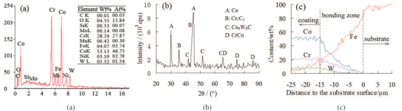
EDS analysis, XRD analysis and EDS line scanning results along the depth direction of the coating are presented in Figure 2. As shown in EDS analysis of the coating (Figure 2a), the coating has 4.55% oxygen element (mass fraction, wt %) which does not exist in the Co-Stellite 6 electrode, whereas the content of other elements is close to that of Co-Stellite 6 (Table 1). It is owing to the fact that, during ESD process the shielding gas is partly broken down by the local high temperature, then the melted electrode materials take reactions with surrounding air to form oxides14.
Figure 2b shows XRD analysis of the coating, phase composition of the coating mainly contains Co, Cr7C3, Co6W6C, CrCo. The chromium-rich carbides Cr7C3 formed during ESD process have stable face-center-cubic structure, it makes a contribution to high macrohardness and good abrasive wear resistance of the coating. The well distribution of Co6W6C and CrCo can refine the microstructure and improve the creep rupture strength of the coating effectively. As presented in this figure, Co has the highest diffraction peak. That’s because Co content of the electrode is much higher than other elements, besides taking reactions to form alloy compounds (such as Co6W6C and CrCo), it is also deposited in the coating at atomic state which refines the microstructure of the coating obviously.
Figure 2c is EDS line scanning results of the coating along the depth direction. As seen in this figure, element content of Co-Stellite 6 such as Co, Cr, W is stable in the coating and drops down in the bonding zone, whereas Fe content (main element of the substrate) increases in the bonding zone. That’s because the electrode materials and the substrate materials mix with each other in the bonding zone at the initial ESD stage. It also gives evidence that the coating makes metallurgical bonding with the substrate.
3.3.
Microhardness of the coating
Microhardness distribution of the coating is given in Figure 3. Average microhardness of the coating is 827.9 HV0.5, which is about 3.6 times that of the substrate (250.2 HV0.5). That’s because the strengthening phase carbides such Cr7C3 and Co6W6C formed during ESD process can improve the intensity and hardness of the coating significantly. As seen in this figure, microhardness fluctuates slightly within 781.7-836.6 HV0.5 in the coating, and gets a maximum value of 836.6 HV0.5 at about 0.1 mm under the coating surface. It attributes to the fact that, discharge craters and micropores make the microhardness of the coating surface layer is slightly lower than that inside the coating. The result also shows that, microhardness decreases sharply in the bonding zone, and drops to 246.3 HV0.5 at the coating-substrate boundary. As analyzed before, the substrate materials transit to the electrode that makes the coating appear dilution phenomenon in the bonding zone15,16,
thus microhardness in the bonding zone decreases. Figure 2. EDS analysis (a), XRD analysis (b) and EDS line scanning results (c) of the coating.
the range of 0.4-1.2 mg when test load increases, whereas for the substrate, it keeps obviously increasing beyond 1.7-5.9 mg that is about 4.2 times that of the coating at the same condition. Figure 4b shows that, with test load increasing, friction coefficient of the coating first decreases and then increases in the range of 0.1-0.27. The analytic reasons for better wear resistance of the coating are listed as follows: a) the substrate surface after strengthening treatment possesses higher hardness and lower stacking fault energy; b) under the influence of local high temperature, the coating microstructure changes its face-centered-cubic structure to a hexagonal-close-packed structure; and c) the electrode materials are deposited in the coating in the form of strengthening phase carbides and additional Co element infiltrates in the coating at atomic state, which helps to improve the coating wear resistance significantly.
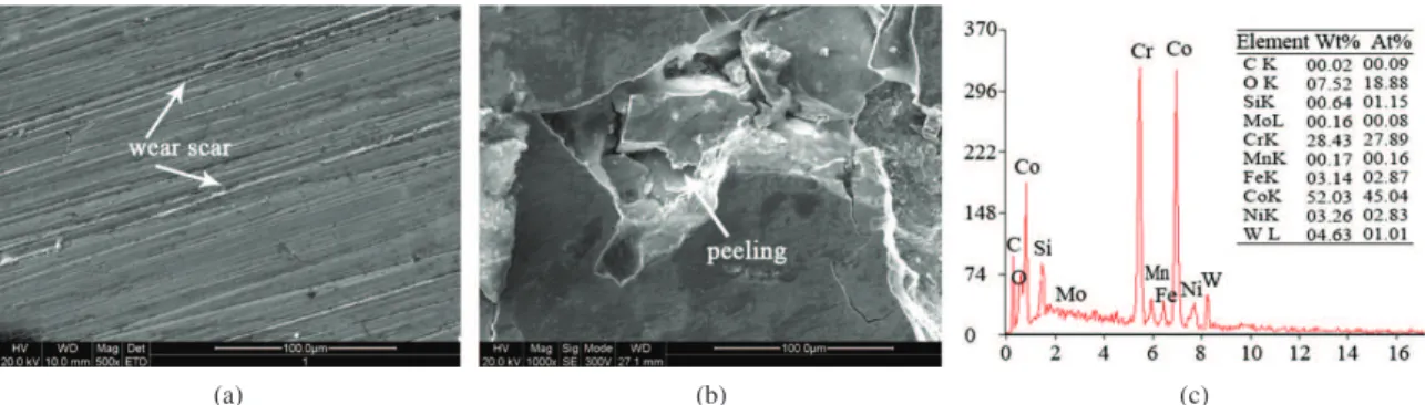
temperature continues rising, and the worn particles fail to remove from the worn surface in time, accordingly the worn surface appears obvious scratches and peelings (Figure 5b), so as to friction coefficient increases. The EDS analysis shows that (Figure 5c), oxygen content in the worn surface is 7.52% that is 1.63 times that of the original coating (Figure 2a). It indicates that, the worn surface is oxidized under heavy load condition. Main wear mechanism at the heavy load stage is fatigue wear and along with oxidation wear.
3.4.2. Rubbing speed influence on tribological properties of the coating
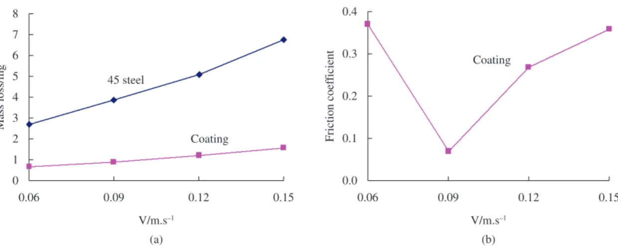
Wear tests at different speed conditions were conducted at a fixed load of 10 N. Mass loss and friction coefficient of the coating versus rubbing speed are presented in Figure 6. Figure 6a shows that, when speed increases, mass loss of
Figure 4. Mass loss and friction coefficient variation versus test load at 0.12 m/s. (a) Mass loss at 0.12 m/s; (b) Friction coefficient at 0.12 m/s.
the coating is in the range of 0.7-1.5 mg, and mass loss of the substrate is in the scope of 2.7-6.8 mg. At the same test condition, mass loss of the substrate is about 4.5 times that of the coating, the coating shows outstanding wear resistance. As shown in Figure 6b, friction coefficient of the coating decreases first and then increases in the range of 0.07-0.37 when rubbing speed increases, and gets a minimum value of 0.07 at 0.09 m/s.
Worn surface morphology and EDS analysis under different speed conditions are shown in Figure 7. At the low speed stage, the coating with high hardness and compact structure presents slight worn morphology (Figure 7a), main wear mechanism of the coating is abrasive wear. With speed going up, the accumulated heat energy makes the coating materials become soft, so friction coefficient of the coating decreases (Figure 6b). When speed continually increases, surface materials occurs peeling and flaking phenomenon, therefore the worn surface presents severe scratches and worn particles (Figure 7b), and accordingly friction coefficient rises up. Main wear mechanism of the coating at high speed is fatigue wear. As shown in Figure 7c, the worn surface at high speed condition has 7.22% oxygen element, which is much higher than that of the original coating. It indicates that oxidation wear exists in the coating under high speed condition.
4. Conclusions
The Co-Stellite 6 coating with a thickness of 0.5 mm was deposited onto 45 carbon steel by ESD technology. The coating possesses refined and compact microstructure with no obvious microcracks and micropores. Phase composition of the coating mainly contains Co, Cr7C3, Co6W6C and CrCo which refine the microstructure and improve the hardness and wear resistance of the coating remarkably. The bonding zone under the coating is formed by mixed materials of the electrode and the substrate. The coating makes metallurgical bonding to the substrate with excellent bonding intensity and stability.
Microhardness of the coating is improved significantly with an average value of 827.9 HV0.5, which is about 3.6 times that of the substrate. Microhardness decreases in the bonding zone along the coating depth direction towards the substrate. Under the same experimental condition, mass loss of the substrate is about 4.2-4.5 times that of the coating, the coating shows excellent wear resistance. Main wear mechanism of the coating is abrasive wear at low speed or low load condition, and fatigue wear at high speed or heavy load condition, and along with oxidation wear at the latter situation.
Acknowledgments
This project was financially supported by the National Natural Science Foundation of China (No. 50875261). Figure 7. Worn surface morphology and EDS analysis under different speed conditions at 10 N. (a) Worn surface morphology at 0.06 m/s, 10 N; (b) Worn surface morphology at 0.18 m/s, 10 N; (c) EDS analysis of the worn surface at 0.18 m/s, 10 N.
South University of Technology. 2005; 12(S2):207-210. http:// dx.doi.org/10.1007/s11771-005-0042-9
4. Zhu YZ, Yin ZM and Teng H. Plasma cladding of Stellite 6 powder on Ni76Cr19AlTi exhausting valve. Transactions of
Nonferrous Metals Society of China. 2007; 17(1):35-40. http://
dx.doi.org/10.1016/S1003-6326(07)60044-2
5. Xu YT, Xia TD and Huang YL. Microstructures comparison of Stellite 6 alloy by self-propagating high-temperature synthesis and cast HS111 alloy. Rare Metal Materials
and Engineering. 2009; 38(8):1333-1337. http://dx.doi.
org/10.1016/S1875-5372(10)60070-7
6. Sheldon GL and Johnson RN. Electro-spark deposition: a technique for producing wear resistant coatings. In:
Proceedings of 4th International Conference on Wear of
Materials; 1985; Vancouver. Washington: American Society
of Mechanical Engineers (ASME); 1985. p. 388-396. 7. Di P, Gu WS and Zhu SG. Effect of electrospark alloying
process on microstructure and properties of the coating. Journal
of Donghua University(English Edition). 2002; 19(4):95-97.
8. Liu J, Wang RJ and Qian YY. The formation of a single-pulse electrospark deposition spot. Surface & Coatings
11. Dolinšek S, Tušek J and Kampuš Z. ESD (Electrospark Deposition) for surfacing of DMLS (Direct Metal Laser Sintering) tools. In: Proceedings of 12th International Scientific Conference on Achievements in Mechanical &
Materials Engineering; 2003; Gliwice-Zakopane. Amsterdam:
Elsevier; 2003. p. 1103-1106.
12. Tušek J, Kosec L, Lešnjak A and Muhič T. Electrospark deposition for die repair. Metabk. 2012; 51(1):17-20. 13. Gould J. Application of electro-spark deposition as a joining
technology. Welding Journal. 2011; 90(10):191-197. 14. Wang JS, Meng HM, Fan ZS, Yu HY and Sun DB.
Microstructure and properties of the YG8 ESD coating on a cast steel roll. Journal of University of Science and Technology
Beijing. 2009; 31(9):1152-1157. (in Chinese).
15. Tang CB, Liu DX and Wang Z. Electro-spark strengthened titanium alloy surfaces by using silicon electrode and their wear resistance properties. Mechanical Science and Technology for
Aerospace Engineering. 2011; 30(2):226-232. (in Chinese).