Marko Ackermann
University of Stuttgart Institute of Eng. and Computational Mechanics Stuttgart, Germany
Fabio G. Cozman
[email protected] University of São Paulo – USP Escola Politécnica 05508-030 São Paulo, SP, Brazil
Automatic Knee Flexion in Lower
Limb Orthoses
Lower limb orthoses are often plagued by a high rejection rate, due both to the excessive effort demanded from their users and to the lack of aesthetics of the resulting gait. These factors are caused, to a great extent, by the fact that orthoses force the whole gait to be performed with the knee articulation in full extension. This work presents a light and compact device, with a low energy consumption, that can improve the performance and the gait aesthetics of knee-ankle-foot orthoses (known as KAFO). To do so, we explore the natural dynamics of the lower limb through a spring that is attached to a standard orthosis system. We also add control circuitry, a small electric motor, sensors and microprocessors to the standard orthosis, so that we can control the whole gait in a relatively natural manner. We have designed the system through a large set of simulations and have shown that the passive dynamics of the lower limb, driven by a burst of energy from a spring at the beginning of the swing phase, is sufficient to reduce the compensation mechanisms required during the gait with orthosis. Thus, this strategy is an alternative to existing solutions relying on functional electrical stimulation (FES), which suffers from limitations such as rapid muscle fatigue and difficult motion control. We describe the design of the device, the model adopted for the swing phase of the gait, the numerical simulations performed and the tests we have conducted.
Keywords: lower limb orthoses, KAFO, knee flexion, biomechanics
Introduction
1KAFOs (knee-ankle-foot orthoses) are prescribed to paraplegic
patients with low level spinal cord injury and with good control of the trunk muscles. According to approximate data from AACD (Associação de Assistência à Criança Deficiente - Association for the Assistance of Handicapped Children), among the patients that could use lower limb orthoses, the rejection rate is as high as 95%; the majority of the patients opts for wheelchair locomotion. The most important reasons for such a rejection rate are the excessive effort demanded from the patients to walk and the lack of aesthetics of the resulting gait. These factors are caused, to a great extent, by the fact that orthoses force the whole gait to be performed with the knee in full extension. The literature presented in the next section suggests the importance of improving the gait with orthoses by implementing automatic knee flexion.
This article describes the development of a new device capable of providing knee flexion for orthoses during the swing phase of the gait. In order to produce a light and energy-saving system, we exploit the natural dynamics of the gait. We propose a system whose main actuator is a spring that flexes the knee joint at the beginning of the swing phase. After the knee flexion, the spring is decoupled and the knee reaches its extended position in an entirely passive way. As far as we know, this is an original strategy that leads to an energy-saving gait by reducing the compensation mechanisms required during the gait with conventional orthosis. Our strategy seems to be a viable alternative to the so-called hybrid orthoses, recently proposed in the literature (Gharooni, Heller and Tokhi, 2000; Durfee and Rivard, 2005), which rely on the use of functional electrical stimulation (FES) and present important limitations such as rapid muscle fatigue, high complexity and difficult motion control.
A two-degrees-of-freedom model of the lower limb was used to simulate the swing phase, to design the device, and to study the sensitivity of the system behavior to perturbations in the parameters of the orthosis and lower limb. A prototype was built and tests with a single patient were performed. The analysis performed through simulations and tests with a patient has demonstrated the potential of the proposed strategy in improving traditional KAFOs and has shown the need of further improvements of the device.
Paper accepted July, 2009. Technical Editor: Agenor T. Fleury
Literature Review
Importance of Knee Flexion during Gait
In normal walking, knee flexion during the swing phase leads to foot clearance, that is, the foot does not touch the ground during the swing phase. In the absence of knee flexion, subjects have to compensate by either hiking the pelvis, or by circumducting the leg, or by vaulting on the contralateral limb (Perry, 1992). These strategies are, however, less efficient than flexing the knee. Indeed, Abdulhadi et al. (1996) showed an increase of 20% in oxygen consumption when the knee joint of a person with normal gait is immobilized. Allard et al. (1997) showed that the vertical oscillation amplitude of the center of mass of a person who uses a conventional KAFO increases 65% when compared to normal gait. A substantial increase in the amplitude of the center of mass motion, when immobilizing the knee unilaterally, was also observed by Ackermann and Gros (2005). Large increases in O2 rate and cost are also reported by Waters and Mulroy (1999) for the gait with orthosis in comparison to the normal gait. Such results show the inefficiency of the gait when conventional orthoses with locked knee are used.
Several authors have studied knee flexion as an improvement to gait quality. Greene and Granat (2000), for instance, showed that a knee flexion associated to an ankle flexion during the swing phase of a paraplegic person can lead to a reduction of the effort required from the patient. Kaufman et al. (1996) showed through experiments that the use of a KAFO that allows knee flexion during the swing phase can reduce the energy consumption when compared with a conventional KAFO. Knee flexion is not only functionally valuable; it also provides a more normal-looking gait that surely increases the aesthetics of the gait and, as a result, can also substantially contribute to the reduction of the aforementioned rejection rate.
Systems for Automated Gait
In order to promote knee flexion in a simple and energy-saving way, this work exploits the natural dynamics of the human gait. In the following paragraphs we summarize two lines of previous work that have used this concept and that have inspired the present work.
the knee flexion at the end of the swing phase, they use FES to stimulate the knee extensor muscles against the action of the spring. The bending of the knee during the stance phase is prevented by a powerful brake system. Additionally, the hip joint is equipped with a cable-ratchet whose function is to keep the hip joint flexed during knee extension at the end of swing phase.
In a different line of work, researchers have considered the design of systems that cleverly explore dynamics to obtain an energy-saving gait. The classical work of McGeer (1990) explores and develops the concept of Passive Dynamic Walking. It demonstrates mathematically that it is possible to build a two-legged machine capable of walking on a shallow slope in a passive way, with energy provided solely by gravity forces, without any active control. Camp (1997) demonstrates that the implementation of a simple open-loop controlled actuation is sufficient to promote a stable gait on an even surface. According to Pratt (2000), very simple or even open-loop control strategies that explore the natural dynamics of the human gait, applied to prosthetic, orthotic or robotic systems, can lead to energy-saving gait patterns that are very similar to normal ones. In fact, this previous work shows the ballistic nature of the swing phase, evidenced by the low muscle activation measured during the swing phase in walking. This evidence suggests that a small addition of energy to the system in this phase can lead to a normal-looking kinematics and contribute to foot clearance.
A New System for Automatic Knee Flexion in
Knee-Ankle-Foot Orthoses
Here we propose a new solution for promoting knee flexion on KAFOs. The solution exploits the natural dynamics of the gait as follows:
• the required energy to flex the knee at the beginning of the swing phase is provided by a spring, and
• the necessary knee extension at the end of the swing phase is reached in an entirely passive way by simply decoupling the spring from the knee joint after a specific knee flexion.
The patient commands the unlocking of the knee joint to initiate the swing phase; the knee is then automatically locked at the end of the swing phase as soon as it reaches its extended position. The storage of energy in the spring is made by a small motor during the whole period in which the knee joint is locked. Throughout the gait, the patient uses crutches to maintain balance; note that we intend to improve gait conditions, but at this point we do not intend to eliminate the use of accompanying crutches.
1 2 3 4 5 6 7 8 9
Figure 1. Scheme of the gait generated by the proposed strategy.
A drawing that explains our proposal is shown in Fig. 1. The figure shows a swing phase whose kinematics is similar to that of the normal gait, and the snapshots correspond to the following steps: 1. The knee joint is unlocked through a command issued by the user of the orthosis (in our prototype, a small button in a crutch was used for this purpose).
2. The knee flexes under the effect of the spring. The hip flexes as a reflex of the knee flexion.
3. As soon as the knee reaches a specific knee flexion angle, the spring is decoupled and stops to exert moment on the knee joint.
4. As an effect of the kinetic energy acquired by the lower limb before the decoupling of the spring, the knee and the hip joints keep flexing until they, under the decelerating effect of the gravity, reach their maximum flexion level.
5. The knee and hip joints extend under the effect of gravity. 6. The knee joint reaches its totally extended position, while the hip joint is still flexed. The knee joint is automatically locked, as soon as it reaches its totally extended position. A small motor begins to store energy on the spring. This storage takes place while the knee joint is locked in its extended position.
7. Due to the conservation of momentum the entire limb advances after the knee locking (the hip joint flexes).
8. Beginning of the stance phase (after heel strike). 9. Stance phase.
This is, to the best of our knowledge, an original strategy that leads to a very simple solution, because it does not require FES or any type of actuator or locking device at the hip joint. Consider the alternatives, some of which have been explored in the literature (Literature Review). The use of a motor directly coupled to the joint to flex the knee would substantially increase the energy consumption by blocking the natural dynamics, and would require more power from the batteries. The use of FES to extend the knee at the end of the swing phase, as proposed by Gharooni et al. (2001), is an interesting alternative, but increases considerably the complexity of the system and compromises its viability. Moreover, FES suffers from further limitations such as rapid muscle fatigue and difficulty to precisely control joint torques. Also note that their solution requires a powerful brake system, a feature that is not compatible with the requirement that the system must be a portable one. We comment on our solution for a braking mechanism later.
Note that to achieve an effective swing phase, a knee flexion must be accompanied by a hip flexion (negative α in Fig. 2). In our proposed approach, hip flexion is obtained by actuating the knee, that is, an actuator coupled to the hip joint is unnecessary. A flexion moment applied at the knee leads to hip flexion due to the dynamic coupling between hip and knee. It should be noted that Gharooni et al. (2001) use a hip ratchet to keep the hip joint flexed at the end of the swing phase and to improve foot clearance. However, the analysis described in the next section shows by means of numerical simulations that the hip flexion induced by knee flexion is sufficient to provide a satisfactory swing phase and foot clearance. This analysis was confirmed by experiments performed with a patient, as described further on.
During the stance phase we simply keep the knee joint locked in full extension. This strategy avoids the need for an actuator to maintain the knee extended. Gharooni et al. (2001) use a powerful braking system to keep the knee joint extended. Our solution is simpler, as the use of a full-fledged braking system is incompatible with a portable solution. In essence, we have replaced a brake by a compact and energy-saving locking ring (Ackermann and Cozman, 2002b) which automatically locks the joint under the action of gravity when full extension is achieved, and unlocks it through a small and energy-saving solenoid.
Analysis and Simulation of the Lower Limb System
Dynamics
the knee is maintained in full extension and the system remains with a single degree of freedom, the hip flexion angle.
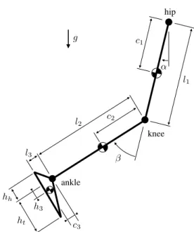
The model consists of a double pendulum in the sagittal plane with two degrees of freedom, hip extension angle α and knee flexion angle β (Fig. 2). The hip joint is a hinge fixed to a stationary coordinate system. As conventional lower limb orthoses allow a very limited ankle motion, the foot is fixed to the shank at the ankle’s neutral position as depicted in Fig. 2. The segments’ mass, mass moment of inertia and position of the center of mass are estimated using relations in the literature (Winter, 1990; de Leva, 1996). Linear viscous damping coefficients at the hip and knee joints of 0.7 N.m.s are based on experiments by Stein et al. (1996). The passive joint moments due to passive muscle properties and other joint structures are modeled using the expressions by Riener and Edrich (1999). All the anthropometric parameters of the model, corresponding to the patient's body mass, 53.6 kg, and height, 1.71 m, are listed in Tab. 1. The equations of motion have been derived symbolically using the software NEWEUL (Kreuzer and Leister, 1991) and are documented in Appendix 1. Notice that the model is valid only during the swing phase of the gait and, thus, does not constitute a complete gait model. For a detailed explanation of the model refer to Ackermann (2002).
hip
knee
ankle
l1
h3
c2
c1
ht
α
l2
l3
g
β
c3
hh
Figure 2. Model of the lower limb in the swing phase with two degrees of freedom.
The simulation consists of two phases, one before the knee locking event and the other after the knee locking event. Previous to the impact, the double pendulum model (Appendix 1) is numerically integrated from a static initial condition, where the hip is extended by 20 degrees, α = 20o, and the knee is extended, β = 0. After knee locking at the end of the swing phase, the knee joint is constrained to the extended position and the only remaining degree of freedom is the hip angle. The knee locking event is modeled as an instantaneous, inelastic collision where the total angular momentum is conserved. Appendix 2 contains the expression regarding the angular velocity of the hip immediately after the impact and the angular velocities of the hip and knee joints immediately before the impact. The equation of motion of the resulting one-degree-of-freedom model is then forward integrated from the initial condition corresponding to the position of the limb at impact and the angular speed of the hip immediately after the impact.
Table 1. Anthropometric parameters of the model. Refer to the equations of motion in Appendix 1.
Parameter Value Unit
total patient body mass 53.6 kg
total patient stature 1.71 m
mass thigh (m1) 5.36 kg
mass shank (m2) 2.49 kg
mass foot (m3) 0.78 kg
mass orthosis (m4) 1.50 kg
moment of inertia thigh (I1) 0.0982 kg.m2
moment of inertia shank (I2) 0.0402 kg.m2
moment of inertia foot (I3) 0.0032 kg.m2
length thigh (l1) 0.419 m
length shank (l2) 0.421 m
“vertical” length foot (l3) 0.067 m
position CM thigh (c1) 0.181 m
position CM shank (c2) 0.182 m
“vertical” position CM foot (c3) 0.033 m
“horizontal” position CM foot (h3) 0.029 m
“horizontal” ankle – toes (ht) 0.085 m
“horizontal” ankle – heel (hh) 0.174 m
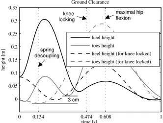
Figures 3 and 4 show the results of a representative simulation performed for a linear angular spring with a stiffness of 17 N.m.rad-1 and a neutral angle of 60o (solid lines). These conditions imply the decoupling of the spring when the knee achieves a flexion angle of 60o. The dashed lines show the simulated results for the case of knee locked in full extension during the whole swing phase for comparison. The figures indicate the time instants for three events: spring decoupling, knee impact, and maximal achieved hip flexion after knee locking. Figure 3 depicts the hip and knee joint angles throughout the simulation, whilst Fig. 4 shows the height of the two ground collision candidates, heel and toes, which are modeled as points at the extremities of the foot as shown in Fig. 2.
The knee angle trajectory shows a normal pattern with a maximal knee flexion of about 70o and duration up to knee locking of 0.474 s, close to the duration of the swing phase during normal walking (about 0.4 s). The maximal achieved hip flexion of about 25o agrees well with normal walking patterns and decreases to about 20o before the full extension of the knee. The latter occurs due to the knee extension and gravitational effects; it cannot be counterbalanced by the patient, because of his lack of control on the hip flexor muscles. Nevertheless, the hip flexes again after the knee locking due to the angular momentum of the shank, and the hip flexion, despite being inferior to the normal one, is still sufficient to provide enough ground clearance as shown by the plot on Fig. 4. This is a central point in our solution, as explained previously.
0 0.134 0.474 0.608 1 −40
−20 0 20 40 60 80
Hip and Knee Angles
time (s)
angle (degrees)
spring decoupling
knee locking
maximal hip flexion
α (hip extension)
β (knee flexion)
α (for knee locked)
α (Winter, 1990)
β (Winter, 1990)
Figure 3. Simulated hip and knee angles for the knee flexion device proposed (solid lines), and hip angle for the simulation with knee locked in full extension (dashed line). Experimental data from Winter (1990) is added for comparison assuming that heel contact coincides with the knee locking event.
0 0.134 0.474 0.608 1
0 0.05 0.1 0.15 0.2 0.25 0.3 0.35
Ground Clearance
time [s]
height [m]
3 cm spring decoupling
knee locking
maximal hip flexion
heel height
toes height
heel height (for knee locked)
toes height (for knee locked)
Figure 4. Simulated height of the collision candidates, heel and toes, for the knee flexion device proposed (solid lines) and for the knee locked in full extension (dashed lines) for comparison.
We have performed several simulations to design the spring so as to achieve a relatively normal-looking swing phase and to minimize the necessary hip rise; an extensive discussion of results can be found in Ackermann (2002). We have been able to specify springs that lead to a lower limb kinematics similar to the normal one (Fig. 3).
We have designed a linear angular spring with stiffness between 14 and 17 N.m.rad-1 and a decoupling angle (neutral angle) of 60o. These features lead to a lower limb motion similar to the normal one, and increase foot clearance with respect to the one achieved for conventional orthoses. The high sensitivity of the lower limb dynamics to the passive stiffness and the friction at the joints is a more delicate matter. Higher joint frictions, for example, prevented the decoupling of the spring or the passive achievement of full extension and locking of the knee at the end of the swing phase. These will be discussed further on and were also observed during the experiments. Therefore, a finer and patient-specific tuning of the system properties might be necessary to guarantee a satisfactory performance.
Prototype
We have built a prototype, depicted in Fig. 5, that consists of four sub-systems:
i Spring system (including a steel spring), and the mechanical structure of aluminum, that is attached to a conventional orthosis.
ii Locking system, which keeps the knee joint locked and extended during the stance phase, and keeps the knee joint free during the swing phase of the gait. We have developed a new locking device, which is very light, energy-saving and compact (Ackermann and Cozman, 2002b). It contains a moving ring, which locks the knee joint, and a small solenoid commanded by the control system capable of unlocking the joint by displacing the ring. Refer to the schematic drawing of the locking system in Fig. 6. The locking of the joint occurs automatically, under the effect of gravity, as soon as the joint reaches full extension. A small burst of energy into the solenoid is enough to unlock the joint. Its total weight is about 0.2 kg.
iii Spring storage system whose function is to store energy in the spring while the knee joint is locked. This system is composed of a small 12V DC motor, a 43:1 planetary speed reducer, a pulley and a steel cable connected to the free stick of the spring and to the pulley. The system is capable of storing energy in the spring in about 1.3 s. The motor and speed reducer set weights about 0.18 kg.
iv
Control system, which controls the spring storage system and the locking system by means of the information obtained from the sensors. It contains a microprocessor (PIC16F84), which receives information from two sensors (locking knee and coupling of the spring) and from one button commanded by the patient to initiate the swing phase of the gait. The microprocessor controls the solenoid, the motor and a knee locking signal to inform the patient that the knee has been safely locked at the end of the swing phase.Figure 5. Prototype.
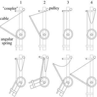
A drawing indicating the system operation is presented in Fig. 7. The numbers in the figure correspond to the following steps: 1. As soon as the knee extends at the end of the swing phase, the
2. Elastic potential energy is stored in the spring during almost the whole period in which the knee joint is locked and extended.
3. The free stick of the spring is mechanically coupled. An optical sensor detects the coupling and the control system turns off the DC motor.
4. The control system turns on the motor in the opposite direction, so as to relax the tension in the cable. After a pre-defined period, the control system enables the start of the swing phase, which is commanded by the patient through a button.
5. As the patient commands the unlocking of the knee joint, the spring begins to transfer energy to the lower limb, flexing the knee joint.
6. As soon as the knee flexion angle reaches the neutral angle of the spring, the free stick of the spring is mechanically decoupled, so as to allow the totally passive motion of the lower limb.
7. Under the decelerating effect of the gravity, the knee begins to extend.
8. The knee joint reaches its full extension and is automatically locked by the locking system at the end of the swing phase.
pper part orthosis
bearing locking
ring
joint
locked joint unlocked joint
solen cable
knee flexio ower part
orthosis
Figure 6. Schematic drawing of the locking system.
1 2 3 4
pulley
cable
angular
7 "coupler"
spring
Figure 7. Drawing indicating the system operation.
Tests
To verify the central ideas of this work, we have performed two tests with a paraplegic patient of AACD, user of a conventional KAFO produced by AACD. The experimental protocol was approved by the head of the Bioengineering Laboratory at AACD, and by the patient's heath care providers at AACD, an orthopedist and a physiotherapist. The patient provided his informed consent after a detailed explanation of the experimental procedure.
The first test was performed after the construction of the prototype's mechanical components, including the spring, the “coupler”, and the locking system. The objective was to verify whether both the actuation strategy proposed and the designed spring would lead to the desired lower limb motion. The second test was performed after the DC motor, the solenoid, sensors and the control circuitry were added. The main objective of the second test was to verify the appropriate functioning of the complete system.
The experiments were performed at AACD. The patient was 25 years old, 1.71 m, 53.7 kg, paraplegic level T12 (lower level spinal cord injury SCI), with low spasticity and good control of the trunk muscles. He was positioned between parallel bars in such a way as to emulate crutches. The left lower limb was positioned on a 0.15 m stage, with the patient's right lower limb free. The right lower limb, to whose orthosis the prototype was coupled, was held backwards (hip extension of about 20o) simulating the initial position of the lower limb immediately before the beginning of the swing phase. A single step was video recorded. Table 2 presents information on time and the angles reached by the hip (α) and knee (β) joints during the experiment, measured by frame-by-frame analysis of the video recording.
Table 2. Times and angles reached by the hip joint (α) and knee joint (β).
The approximate values were obtained through a frame-by-frame analysis of a video recording.
Event Time (s) α β
beginning 0 ~23o 0o
spring decoupling 0.20-0.23 - ~60o
maximal β ~0.27 - 60o-65o
knee locking ~0.47 - 0o
max. hip flexion ~0.73 ~-25o 0o
First Test
• As observed in Tab. 2, some salient features of the normal swing phase were reproduced. For instance, the time between the beginning of the swing phase and the extension of the knee amounts 0.47 s, compared with approximately 0.39 s in normal gait (Winter, 1990). Furthermore, the maximal achieved knee and hip flexion angles agree fairly well with the ones for normal gait. This confirms the potential of this new system to improve the gait with orthoses.
• The knee flexion speed was substantially higher than that observed in the normal gait. This is caused by the type of spring used, which applies a high torque on the joint at the very beginning of the swing phase.
• The patient is able to control the walking velocity by controlling the initiation of the swing phase, or by controlling the instant of heel contact after knee locking.
Second Test
• The second test demonstrated that the system functions mostly accordingly to specifications.
• Despite the fact that the test conditions were very similar to those of the first test, the behavior of the lower limb observed was substantially different. For instance, the full knee extension achieved at the end of the swing phase predicted by the computational simulation and observed during the first test did not happen in the second test. After analysis, we concluded that this difference occurred due to a relevant increase in the passive stiffness of the patient's joints. Substantial variations in the lower limb behavior due to variations in the knee joint stiffness had been predicted by the performed simulations. A possible explanation for the mentioned increase in joint stiffness could be the long period (about 1 year) between the first and second experimental sessions, in which the patient had rarely worn the orthosis and had not attended the physiotherapy program regularly. This fact suggests the importance of considering carefully the passive moments at the joints.
Conclusion
This work presents a new, compact and energy saving device that provides knee flexion for lower limb orthoses of type KAFO. The idea advocated here is to exploit the natural dynamics of the lower limb. We propose the use of a spring at the knee joint, and the following strategy: store energy in the spring during the whole period in which the knee joint is locked in full extension (requiring low power), and release energy at high rates during the beginning of the swing phase (to provide knee and hip flexion); as the knee reaches a specified flexion angle, decouple the spring, leading to an entirely passive dynamic behavior of the lower limb, and causing the total extension of the knee at the end of the swing phase.
This solution can partially restore normal gait kinematics to the lower limb during the swing phase of the gait, as shown through simulations and tests. The provided knee flexion reduces the compensation strategies needed to guarantee ground clearance during the swing phase and increases the aesthetics of the gait. These two improvements can reduce the high rejection rate of lower limb orthoses.
The prototype only requires the user to command the initiation of the swing phase. The DC motor is capable of rearming the spring in approximately 1.3 s and of releasing the cable in approximately 0.5 s. Considering in addition the duration of the swing phase, ~0.47 s, the prototype allows for a maximal walking cadence of approximately 55 steps/min. The prototype is light (1.26 kg) and energy-saving (a 0.27 kg NiMH battery can provide an autonomy of about 2300 steps). The battery and the control systems enclosed in a 0.149 x 0.097 x 0.063 m box attached to a waistband weigh 0.47 kg. Some improvements, left to future work, were suggested by our simulations and experiments:
• The simulations and the tests with the patient indicated the high sensitivity of the kinematics of the system to joint stiffness. Given the substantial variability of this feature in the population, strategies to reduce this sensitivity are required; an
idea is to apply a personalized stiffness mechanism in order to neutralize the passive stiffness of the knee joint.
• We have also observed high sensitivity to friction, particularly at the knee joint. This fact shows the importance of minimizing the friction at the joint when the orthosis is designed and built. • The reduction of the knee flexion speed is desirable in order to
further approximate the kinematics of the lower limb to the normal one. One idea here is to use a non-linear spring with an appropriate stiffness curve.
Finally, it seems that simultaneous flexion of ankle and knee during the swing phase would further improve the performance of lower limb orthoses, as it would raise the toes in the middle of the swing phase, thus increasing foot clearance and reducing the need for compensating measures such as hip rise. Besides, an orthosis with ankle flexion would be useful in gait rehabilitation and neuromechanical studies (Gordon et al., 2006). Greene and Granat (2003), for instance, propose a mechanism that provides ankle dorsiflexion simultaneously to knee flexion which could be implemented in conjunction with the knee flexing device described here. We have, in fact, started to investigate an extension of our proposals to ankle flexion. To keep the whole device as a light and simple addition to existing orthoses, the idea is to connect the orthotic foot to a cable attached to the knee spring. As the spring extends during the swing phase, this cable is pulled, causing a dorsiflexion of the ankle.
Acknowledgments
The authors would like to thank the staff of the Laboratory of Bioengineering of AACD, especially Milton Oshiro, for valuable discussions and the assistance during the experimental part of this work. We are grateful to Fernanda Aline Matta Paiva, Pedro Roberto Paterson Carleial, Ricardo Chanwei Chen and Danilo Issamu Moniva for their contributions to the ankle flexion prototype. This work was supported by FAPESP (State of São Paulo Research Foundation).
Appendix 1: Equations of Motion
The equations of motion of the two-degree-of-freedom model of the lower limb with orthosis (shown in Fig. 2) for the swing phase of the gait, before the full extension of the knee, read as
), , ( ) , ( )
(y y k y y q y y
M &&+ & = & (A.1)
where
y
= [α β]T is the vectors of generalized coordinates, M isthe 2x2 symmetric, positive definite mass matrix,
k
is the 2x1- vector of generalized Coriolis forces, q is the 2x1- vector of generalized forces, and their components are+ + + + = 2 2 2 1 2 2 2 1 4 2 1 1 1 ,
1 mc m l 2m cl cos( ) m c
M
β
+ +
+
+ 2 3 32
2 3 1 3 3 1 2
3 cos( ) 2 cos( ) 2
2mll
β
m clβ
ml mcl+ + + + +
+ 1 2 3
2 3 3 1 3 3 2 3
3c 2mhl sin( ) mh I I I
m
β
, 2 1 3 2 1 2l mlm +
+ +
=
= 2,1 2 21cos( ) 321cos( )
2 ,
1 M m c l
β
ml lβ
M + + + + + 2 3 3 1 3 3 2 3 3 2 2 3 2 2
2c ml 2mc l m cl cos( ) mc
m
β
, )
sin( 2 2 3
3 3 1
3
3hl mh I I
m
β
+ + ++ + + + + = 2 3 3 2 3 3 2 3 3 2 2 3 2 2 2 2 ,
2 m c ml 2mc l mc mh
, 3 2 I I + + − −
= 2sin( ) 2 2 21 sin( )
1 2 2
1 m c l
β
&β
m c lβ
&α
&β
k−
+ cos( )
) cos( 2 2 1 3 3 1 3
3hl
β
&α
&β
mhlβ
&β
m−
−2 sin( )
) sin(
2m3l2l1
β
&α
&β
m3c3l1β
&α
&β
), sin( )
sin( 3 31 2
2 1 2
3l l
β
&β
m clβ
&β
m −
(A.2)
+ +
= sin( ) 2sin( )
1 2 3 2 1 2 2
2 m c l
α
&β
mllα
&β
k ), cos( ) sin( 2 1 3 3 2 1 33c l
α
&β
mhlα
&β
m −
+ +
−
= ( 1 1sin( ) 2 2sin( )cos( )
1 g mc
α
m cα
β
q
+ + sin( )cos( ) )
cos( )
sin( 3 2
2
2c
β
α
mlα
β
m
+ + sin( )cos( ) )
cos( )
sin( 3 3
2
3l
β
α
mcα
β
m
− + sin( )sin( ) )
cos( )
sin( 3 3
3
3c
β
α
mhβ
α
m
+ +
+ sin( ) sin( ) )
cos( )
cos( 21 31
3
3h
β
α
m lα
mlα
m
, ))
sin( 1
1
4l
α
+τ
m+ +
−
= ( 2 2sin( )cos( ) 2 2sin( )cos( )
2 g m c
α
β
m cβ
α
q
+ + sin( )cos( ) )
cos( )
sin( 3 2
2
3l
α
β
mlβ
α
m
+ + sin( )cos( ) )
cos( )
sin( 3 3
3
3c
α
β
mcβ
α
m , )) cos( ) cos( ) sin( )
sin( 3 3 2
3
3h
β
α
−mhβ
α
+τ
m
where τ1 and τ2 are the passive moments at the hip and knee joints, respectively, adopted from the literature (Riener and Edrich, 1999; Stein et al., 1996), and the values of the anthropometric parameters employed in the simulations are listed in Tab. 1. The equation of motion for the swing phase after the knee locking is derived from the first of the two equations in Eq. (A.1) by setting
. 0
= = =
β
β
β
& &&Appendix 2: Treatment of Knee Collision and Locking
The locking of the knee immediately after its full extension is modeled as an instantaneous, inelastic impact, where the total angular momentum about the hip joint is conserved. According to this model, the angular velocity at the hip joint immediately after the impact
α
&+ can be computed from the angular velocity at the hip and knee joints immediately before the impact,α
&− andβ
&−, respectively (Schiehlen et al., 2006) as. 1 , 1 2 , 1 1 2 , 2 1 2 ,
1 − − −
− − −
+=
α
−β
=α
+β
α
& & & & & M MM
M (A.3)
References
Abdulhadi, H.M., Kerrigan, D.C., and LaRaia, P.J., 1996, “Contralateral shoe-lift: effect on oxygen cost of walking with an immobilized kne”, Archives of Physical Medicine and Rehabilitation, Vol. 77, No. 7, pp. 670-672.
Allard, P., Lachance, R., Aissaoui, R., Sadeghi, H., and Duhaime, M., 1997, “Able-bodied gait in men and women”, Three-dimensional Analysis of
Human Locomotion, P. Allard, A. Cappozzo, A. Lundberg, and C.L. Vaughan (eds.), John Wiley & Sons, pp. 307-334.
Ackermann, M., 2002, “Sistema de acionamento e travamento para flexão mecanizada de joelho em órteses de membros inferiores” (in Portuguese), Masters dissertation, Escola Politécnica, Universidade de São Paulo, São Paulo, Brazil.
Ackermann, M., and Cozman, F.G., 2002, “Um sistema de travamento para a articulação do joelho de órteses de membros inferiores” (in Portuguese), In: Proceedings of the II Congresso Nacional de Engenharia Mecânica, pp. 116-124.
Ackermann, M., and Gros, H., 2005, “Measurements of human gaits”, Zwischenbericht ZB-144 (technical report), Institute B of Mechanics, University of Stuttgart, Stuttgart.
Camp, J., 1997, “Powered “passive” dynamic walking”, Masters of enginnering project report, The Sibley School of Mechanical and Aerospace Engineering, Cornell University, Ithaca, NY.
de Leva, P., 1996, “Adjustments to Zatsiorsky-Seluyanov's segment inertia parameters”, Journal of Biomechanics, Vol. 29, No. 9, pp. 1223-1230.
Durfee, W. K., and Rivard, A., 2005, “Design and simulation of a pneumatic, stored-energy, hybrid orthosis for gait restoration”, Journal of Biomechanical Engineering, Vol.127, No.6, pp. 1014-1019.
Gharooni, S., Heller, B., and Tokhi, M.O., 2000, “Hybrid spring brake orthosis for controling hip and knee flexion in the swing phase”, Research report no. 764, Department of Automatic Control and Systems Engineering, University of Sheffield, Sheffield, UK.
Gharroni, S., Heller, B., and Tokhi, M.O., 2001, “A new hybrid spring brake orthosis for controlling hip and knee flexion in the swing phase”, IEEE Transactions on Neural Systems and Rehabilitation Engineering, Vol. 9, No. 1, pp. 106-107.
Gordon, K.E., Sawicki, G.S., and Ferris, D.P., 2006, “Mechanical performance of artificial pneumatic muscles to power an ankle-foot orthosis”, Journal of Biomechanics, Vol. 39, No. 10, pp. 1832-1841.
Greene, K.E., and Granat, M.H., 2000, “The effects of knee and ankle flexion on ground clearance in paraplegic gait”, Clinical Biomechanics, Vol. 15, No. 7, pp. 536-540.
Greene, P.J., and Granat, M. H., 2003, “A knee and ankle flexing hybrid orthosis for paraplegic ambulation”, Medical Engineering & Physics, Vol. 25, No. 7, pp. 539-545.
Kaufman, R.K., Irby, S.E., Mathewson, J.W., Wirta, R., and Sutherland, D. H., 1996, “Energy-efficient knee-ankle foot orthosis: a case study”, Journal of Prosthetics and Orthotics, Vol.8, No.3, pp. 79-85.
Kreuzer, E., and Leister, G., 1991, “Programm system NEWEUL'90” (in German), Anleitung AN-24, Institute B of Mechanics, University of Stuttgart.
McGeer, T., 1990, “Passive dynamic walking”, The International Journal of Robotics Research, Vol. 9, No. 2, pp. 504-524.
Perry, J.E., 1992, “Gait Analysis: Normal and Pathological Function”, Charles B. Slack, Thorafare, NJ.
Pratt, J.E., 2000, “Exploiting inherent robustness and natural dynamics in the control of bipedal walking robots”, Ph.D. Thesis, Department of Electrical Engineering and Computer Science – Massachusetts Institute of Technology.
Riener, R., and Edrich, T., 1999, “Identification of passive elastic joint moments in the lower extremities”, Journal of Biomechanics, Vol. 32, No. 5, pp. 539-544.
Schiehlen, W., Seifried, R., and Eberhard, P., 2006, “Elastoplastic phenomena in multibody impact dynamics”, Computer Methods in Applied Mechanics and Engineering, Vol. 195, No. 50-51, pp. 6874-6890.
Stein, R.B., Lebiedowska, M.K., Popovic, D.B., Scheiner, A., and Chizeck, H.J., 1996, “Estimating mechanical parameters of leg segments in individuals with and without physical disabilities”, IEEE Transactions on Rehabilitation Engineering, Vol. 4, No. 3, pp. 201-211.
Waters, R.L., and Mulroy, S., 1999, “The energy expenditure of normal and pathologic gait”, Gait and Posture, Vol. 9, No. 3, pp. 207-231.