A Wireless MAN in Bragança – Digital City
José Carlos Rufino Amaro, Rui Pedro Lopes
([email protected], [email protected])
Instituto Politécnico de Bragança – ESTiG, P5301-857 Bragança, Portugal
Abstract
Following the portuguese Digital Cities Program, twelve Information Society related projects where initiated in the city of Bragança, under a common goal: “to reduce interiority costs”. A wireless network with metropolitan coverage was then built to fulfill the communication requirements, both between institutions and to the Internet. We present here several important design decisions and implementation issues that took place, ranging from wireless protocol choosing, to topology, addressing, routing, scalability considerations, as well as a preliminary performance evaluation. In the end, our wireless MAN proved to solve the connectivity problems, both by providing a performant and economical solution, suited to the application scenario.
I. I
NTRODUCTIONThe city of Bragança was pioneer in the context of the portuguese Digital Cities Program. The Bragança – Digital City (BDC) initiative started formally in the 22nd of February of 1999, with twelve projects from public and private local institutions covering several areas of the so-called Information Society, with a ultimate goal: “to reduce interiority costs”.
The project we present in this paper – the Communitarian Data Network (CDN) [1] – is one of the leading projects of the BDC initiative, having provided, since April 2000, a common data communications backbone and shared Internet access, between partners. In other words, the CDN is a Metropolitan Area Network (MAN), linking every partner of the BDC initiative in a kind of Intranet with a single common gateway to the Internet.
Although based on new technology, with very recent legal context, wireless private networks are expanding in Portugal. However, the CDN was, as far as we know, the very first case in the portuguese Digital Cities scenario, having set up a wireless metropolitan network. The first phase of the project interconnected eight partners of the BDC initiative, but the network welcomes other organizations interested in developing the local Information Society.
In this paper we begin by describing the decision process leading to the adoption of wireless technology. Our main focus, however, will be the technological and practical problems we had to solve in order to fit the solution to our own needs, including topological issues, addressing policies and routing decisions. In the end, we also present preliminary performance measures.
II. B
ACKGROUNDThe choice of the wireless solution became apparent after technological advances and price drops in the wireless arena. Several tests with different equipment brands revealed that the novel IEEE 802.11b [2] standard matched the BDC requisites: good performance at relatively low costs. IEEE 802.11b based equipment operates in the 2,4GHz unlicensed band, using Direct Sequence Spread Spectrum (DSSS), and being capable of rates up to 11 Mbps.
Generically speaking, a wireless solution has a broad set of advantages. To start with, it is not necessary to lease circuits between access points, which would require monthly fees making the solution financially inadequate due to self-sustainability requisites. Also, with wireless, a single connection to an ISP is enough, which allows dividing the operation costs by all the connected institutions. Although having installation costs as well as having to paid for the equipment, it quickly compensates due to the significant transmission rate over traditional leased links and to the absence of accounting. It operates in an unlicensed band and, because it is a private network, the wireless MAN is free from licensing by the Portuguese Communications Institute. Moreover, by avoiding the use of cables to connect access points the impact on the landscape is minimum (antennae measures 45 cm tall or long, according to the orientation).
III. S
OLUTIONThe wireless solution, particularly for the case presented in this paper, has several inherent choices to suit it to the project own needs.
A. Topology
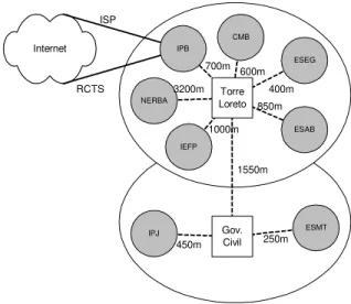
The most important topological constraint was the need for line of sight between the cells center and the remote access points, keeping also in mind that the shorter is the link the higher is the transfer rate. The city landscape as well as the institutions location, defined the position and the number of central routers. To connect all the partners and minimize distances, the network was structured in two cells, spanning approximately 2/3 of the city area (Fig. 1).
Internet
ESMT
IPJ Gov.
Civil
IPB
ESEG CMB
ESAB IEFP
NERBA
Torre Loreto RCTS
ISP
250m 450m
1550m 1000m
850m 400m 600m 700m 3200m
Fig. 1 Wireless MAN topology.
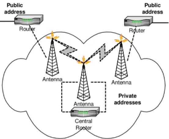
The local network at each partner (Fig. 2) connects to the wireless MAN through a wireless router. The wireless router connects to the WAN port of a hardware firewall appliance. The firewall has two other ports: the DMZ port, allowing for incoming access to local Internet servers (WWW, e-mail, ftp, …), and the LAN/MZ port, behind which resides the local intranet.
MZ
DMZ
Firewall Antenna
Router
LAN
DMZ W AN
Fig. 2 Access point topology.
The Internet gateway of the wireless MAN is at the Polytechnic Institute of Bragança (IPB), where separate leased lines provide for Internet access to local High Schools and to other partners.
B.
Addressing & Routing
Besides using the wireless MAN for Internet access, the project partners also wanted to provide a set of services through their DMZ servers and so the servers must use public IP addresses. A specific IP class C was asked for this purpose. The given class C was sub-netted [3] in several 8 addresses groups each one of them for every partner use. This limit supports the future joining of more institutions to our infrastructure. According to the local topology (Fig. 2), only 4 of the 8 addresses may be used in the servers at the DMZ. The remaining 4 are used as follows: subnet address, broadcast address, one address for the wireless router and one
for the WAN port of the firewall. For High Schools the same sub-netting scheme was applied, although on a different IP range, managed by the RCTS network (a separate government academic network). Therefore, our wireless MAN supports two different public IP networks and care must be taken at the routing level in the wireless routers and in the Internet gateway.
In the latter case, the traffic coming from the wireless MAN is routed to the Internet accordingly to the partners role: institutional traffic is sent through a commercial ISP leased line; educational traffic flows via the RCTS infrastructure.
Traditional routing, either static or dynamic, makes routing decisions based on the destination address. The solution to our problem (to make routing decisions based on the origin address) was to use a Policy Based Routing (PBR) [4] mechanism (Fig. 3).
interface Ethernet0/0 description Wireless MAN
ip address 194.65.107.254 255.255.255.248 ip policy route-map MAPA
…
access-list 10 permit 194.65.107.0 0.0.0.255 access-list 11 permit 194.210.4.0 0.0.0.255 …
route-map MAPA permit 10 match ip address 10 set interface Serial0/0.16 …
route-map MAPA permit 20 match ip address 11
set ip next-hop 193.137.58.30
Fig. 3 PBR rules for traffic splitting.
The traffic from the wireless MAN flows to a router interface (interface Ethernet0/0). Then, the PBR mechanism is activated (ip policy route-map MAPA), and the incoming traffic is matched against two access lists (access-list 10 ... and access-list 11 ...), one for each public IP ranges used. It is also necessary to define policy route maps, which can be regarded as packet filters for incoming traffic. For instance, for map 10 (route-map MAPA permit 10) the matching with access list 10 (match ip address 10) forces routing through the serial interface connected to the ISP (set interface Serial0/0.16). Similarly, the traffic belonging to the other map (match ip address 11) is routed to the RCTS router (set ip next-hop 193.137.58.30).
Hosts within local intranets make use of private IP addresses [5] having outside access through the firewall via network address translation (NAT [6]).
Antenna Router
Antenna Router
Antenna
Central Router
Public address
Public address
Private addresses
Fig. 4 Private IP addresses in the backbone.
This hybrid address usage results evident from the traceroute output given in Fig. 5 (notice, also, the two different public IP classes at the end-points).
1 194.65.107.253 0.802 ms . . . 2 192.168.168.10 4.876 ms . . . 3 192.168.168.25 8.145 ms . . . 4 192.168.168.29 13.680 . . . 5 194.210.4.226 13.938 ms . . .
Fig. 5 traceroute output fragment.
C. Scalability
The topology described above shows wireless building-to-building links in a point-to-multipoint configuration and a single point-to-point link connecting both cells central routers. Although it is mainly used to connect several institutions’ Ethernet based LANs it also supports connecting individual hosts through specific wireless interface cards with PCMCIA, PCI or USB connection.
Scalability issues must consider the increase of the number of hosts in each building sharing the Ethernet network, the increase of the number of concurrent wireless connections as well as the enlargement of the covered geographical area.
The number of hosts Ethernet hosts increase is limited only by bandwidth sharing. The maximum number of hosts is defined by the Ethernet standard and is different according to network topology (switched Ethernet, 2, 10BASE-5, …). Using IP masquerading allows reusing public addresses on several private addressed hosts.
Each central router supports up to 16 building-to-building simultaneous connections per channel to a single vertical antenna and up to three simultaneous channels. This means that it is possible to connect up to 3x16 buildings in the same cell. For direct host to central router wireless connection, the maximum number of connections is 32 per channel and up to three channels. This means that a maximum of 3x32 hosts may be connected to a central router. For more connections, it is necessary to use more cells.
To increase the covered area it is necessary to use higher gain antennae or to create other cells, positioned according to the requisites of line of sight and geographical positioning. The
connection between cells may be wireless through directional antennae.
Off course, for point-to-multipoint links the available bandwidth is divided by all the connections, thus reducing the individual effective transmission rate. For the moment, there is sufficient resources available and the network can grow to three or four times its current dimension in terms of number of connected institutions.
D. Network
Management
One of the CDN project choice was the effective centralization of network management in its different areas (fault, configuration, security, performance and accounting). The advantages are the optimization of human resources, the definition of common management decisions and the altogether evolution of the network. All the institutions share the operation costs thus making this approach also suitable in terms of capital.
The network infrastructure is managed by specialized software that allows remote monitoring and control of routers and firewalls from the IPB.
It is currently being developed a system to allow ubiquitous access to network management information from several terminal, from SNMP based NMS to Web browsers and even WAP capable handheld devices [7].
E. Security
Wireless networks use a shared medium (the ether) so it is relatively easy to intercept any communication. This also occurs on conventional cabled networks, but, because of signal transmission to outside the desired geographical limits, this threat is harder to manage in wireless networks. However, it is common to say that wireless networks are safer than conventional networks [8], because they include several mechanisms (some of them inherent to network operation) that contribute to additional security.
To start with, the spread spectrum technology allows the transmission of low power signals over a broader range of frequencies, achieving greater immunity to noise and interferences. Moreover, it makes harder to intercept a communication. The equipment used in the Digital City wireless network uses DSSS (Direct Sequence Spread Spectrum).
Access point authentication allows network access to specific access points. The CDN routers support this functionality by using a System Access Pass Phrase. To even refine access control, it is theoretically possible to use authentication at the user level, allowing or denying the access to specific users no matter the access point they use.
Network specific characteristics, such as channels, frequencies or spread codes have to be known and shared by all the access points. Moreover, properly configuring access points to act only as routers, and not bridges, assures a better traffic isolation. The wireless routers also support MAC based access control lists and even traffic shaping to limit the transmission rate. Finally, wireless routers use passwords and IP access lists to access configuration and monitoring tools. Logs of network activity may be recorded by syslog or SNMP trap daemons.
Besides specific security support given by the wireless infrastructure, the use of a firewall at the intranet frontier is mandatory. A cheap solution is to use Linux based hosts running ipchains, which also provide IP Masquerading, a NAT-like scheme [10]. This makes possible to reuse almost obsolete PCs. Indeed, that was our first approach. However, management difficulties aroused from the use of heterogeneous and aging hardware, leading to unexpected failures. This led us to the choice of firewall appliances, hardware solutions that, although an additional investment, offered a more reliable solution and less future cost of ownership. These devices allow remote configuration through a VPN, offer NAT, IP/UDP/TCP filtering and support WWW access lists (which may be relevant depending on the local access control policy).
F. Performance
Evaluation
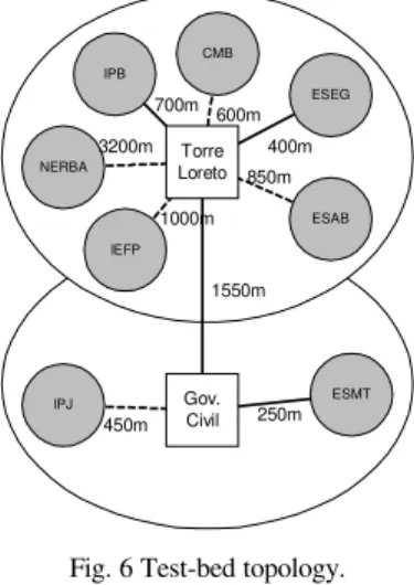
The data throughput is always smaller than the link throughput because of the various protocol overheads. In this paper we will restrict ourselves to the measurement of the
data throughput in a small (but representative) sub-set of network paths (Fig. 6):
1. Point-to-Point (PtP) link between two cells (TL – GC). 2. Point-to-Multipoint (PtM) in the same cell (IPB – TL). 3.
Point-to-Multipoint-to-Point-to-Point-to-Multipoint-to-Point (PtMt PtPtMtP) link across the two cells (IPB – TL – GC – ESMT).
4. Point-to-Multipoint-to-Point (PtMtP) link inside the same cell (IPB – TL – ESEG).
The performance tests were done by using the FTP application (accordingly with the method provided at [11]) and the netpipe [12] tool, the former providing a (somehow) qualitative approach, measuring the network performance from a user’s application perspective, and the latter giving us a more rigorous insight into other network parameters beyond throughput.
For the FTP tests, unidirectional transfers of a 1 Mbyte file were conducted five times, separately, in both ways, and their average transfer time was used to get the throughput.
Bi-directional transfers were also measured (by the formula given at [13]) using five FTP transfers of the same 1 Mbyte file, simultaneously launched, via crontab, on both end-systems (with their clocks previously synchronized by rdate).
ESMT
IPJ Gov.
Civil
IPB
ESEG CMB
ESAB IEFP
NERBA
Torre Loreto
250m 450m
1550m 1000m
850m 400m 600m 700m
3200m
Fig. 6 Test-bed topology.
The FTP test (Fig. 7) shows unequal performance for the various scenarios and uneven numbers for the same scenario when simply varying the transfer direction (< versus >). The bi-directional (<>) throughput, though, is consistently higher. Also, the bandwidth sharing effect in the same cell (PtMtP
scenario) degrades the performance to a great extent, when compared, for instance, to a data exchange across two cells (PtMtPtPtMtP scenario), which benefits from three separate radio channels.
3,9333,846 5,721
3,6563,777 5,378
3,1672,9673,566
1,3451,346 1,849
0,000 1,000 2,000 3,000 4,000 5,000 6,000
> < <> > < <> > < <> > < <>
PtP PtM PtMtPtPtMtP PtMtP
Fig. 7 FTP throughput (Mbps).
On the other extreme, we find the PtP link between two cells, closely followed by the PtM link inside the same cell, as good examples of the maximum expected performance for data bulk transfers inside our wireless MAN, even slightly above levels shown by the manufacturer tests [14].
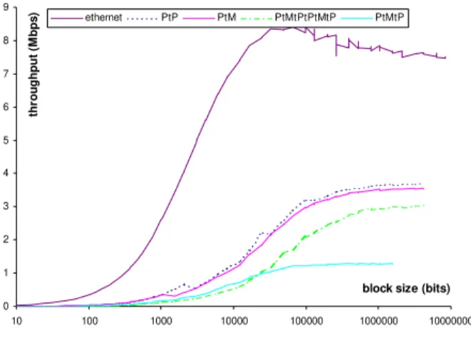
0 1 2 3 4 5 6 7 8 9
10 100 1000 10000 100000 1000000 10000000
block size (bits)
thr
o
u
ghput (
M
bps
) ethernet PtP PtM PtMtPtPtMtP PtMtP
Fig. 8 Throughput (Mbps) x block size (bits).
Fig. 8 shows throughput as a function of the user data block size. The wireless scenarios keep their relative positions given by the FTP test, but the netpipe test clearly shows how the optimal data packet size varies among them. Also, notice how the Ethernet link performs at more than the double data rate, but reaches maximum values much sooner. The later observation seems an evidence of the considerable protocol overhead needed by the wireless links.
0 1 2 3 4 5 6 7 8 9
0.0001 0.001 0.01 0.1 1
time (s)
th
ro
ug
hu
t (
M
b
p
s
) ethernet PtP PtM PtMtPtPtMtP PtMtP
Fig. 9 Troughput (Mbps) x time (s).
Fig. 9 gives the so-called “network signature graph” or “network acceleration graph”. The starting values at the time axis are good approximations to the network latency. As expected, the Ethernet link has the lowest latency (0.27 ms), followed by 2.58 ms, 2.65 ms, 7.07 ms and 5.25 ms, for the various wireless links. Also, for these links, the throughput seems to reach stable values beyond a certain block transfer time (in other words the throughput becomes directly proportional to the block size).
IV. C
ONCLUSIONSWe have presented a wireless network operating in an outdoor scenario with metropolitan coverage. Even though the IEEE 802.11b standard fits best the LAN indoor usage requisites, our equipment has been performing very well in our Digital City, both in terms of throughput and reliability.
Although far from a typical Ethernet indoor LAN, the performance surpasses (albeit with greater variance) the one from current wired leased links and the installation costs pay off quickly by the absence of fixed costs. Issues such as topology, addressing and routing, making use of some well known good practices have also been presented as an example of network engineering. Other relevant topics, such as security, scalability and management, along with an in-depth performance analysis will be the subject of future work.
V. R
EFERENCES[1] Communitarian Data Network Project
(http://rdc.bcd.pt).
[2] IEEE, “802.11b-1999 Supplement to Information technology-Telecom. and information exchange between systems-Local and metropolitan area networks-Specific requirements-Part 11: Wireless LAN Medium Access Control (MAC) and Physical Layer (PHY) Specifications: Higher Speed Physical Layer (PHY) Extension in the 2.4 GHz band”, 1999.
[3] J. Mogul, J. Postel, “Internet Standard Subnetting Procedure”, RFC 950, August, 1985.
[4] CISCO White Paper, “Policy Based Routing”, August, 1996.
[5] Rekhter, Moskowitz, Karrenberg, Groot, “Address Allocation for Private Internets”, RFC 1597, March, 1994.
[6] Egevang, Francis, “The IP Network Address Translator (NAT)”, RFC 1631, May, 1994.
[7] Lopes, Rui, Oliveira, José, “XML exchange of SMI definitions for ubiquitous Network Management”, submitted to MobiCom2001, Rome, Italy, July 2001.
[8] WLANA, “Wireless LANs Security White Paper” (http://www.wlana.com/resource/whitepaper.html).
[9] S. Weatherspoon, “Overview of IEEE 802.11b Security”, Intel Technology Journal Q2, 2000.
[10] Linux IP Masquerade Resource
(http://ipmasq.cjb.net/).
[11] Paul Gortmaker – “Linux Ethernet-Howto v2.7”, May 1999.
[12] Q. O. Snell, A, R, Mikler & J. L. Gustafson – “NetPIPE: A Network Protocol Independent Performance Evaluator”, Ames Laboratory/ Scalable Computing Lab, Ames, Iowa, April 1996.
[13] Amaro, José, Lopes, Rui “Rede Digital Comunitária: uma Rede sem Fios Metropolitana”, CRC2000, Viseu, Portugal, Novembro 2000.