Transition Mechanisms
Edgard Jamhour , Simone Storoz and Carlos Maziero
Graduate Program in Applied Computer Science, Pontifical Catholic University of Paraná, Brazil.
Abstract
The adoption of the Internet Protocol in mobile and wireless technologies has considerably increased the number of hosts that can potentially access the global Internet. IPv6 is considered the long term solution for the IPv4 address shortage problem, but the transition from IPv4 to IPv6 is supposed to be very gradual. Therefore, there will be a long time during which both protocol versions will coexist. To facilitate transition, the IETF has set up a work group called NGTRANS (Next Generation TRANSition) which specifies mechanisms for supporting interoperability between IPv4 and IPv6. This paper describes a new approach for implementing mobile networks with global Internet connectivity using transition mechanisms. It consists in virtually assigning IPv6 addresses to IPv4 hosts without modifying end-user devices by introducing a transparent gateway in the mobile network. The mobile hosts with virtual IPv6 addresses are uniquely addressed through the global IPv4 Internet by using IPv6 addresses from the standard 6to4 addressing scheme or Fully Qualified Domain Names (FQDN). This “extended” transition mechanism permits to deploy mobile networks with global Internet connectivity without requiring public IPv4 addresses, using legacy IPv4 user devices. The mobile hosts with virtual IPv6 addresses can communicate to other hosts with virtual IPv6 addresses or with “true” IPv6 networks.
Keywords: Mobile IP, IPv6, Transition Mechanisms, IP address shortage problem
1 Introduction
In this paper, we address the issue of implementing Mobile IP [1] based networks using private IPv4 addresses. We found Mobile IP implementations in cellular networks technologies such as GPRS (General Packet Radio Service). Mobile IP can also be employed to provide seamless roaming between wireless local-area networks (WLANs), or even across different types of infrastructures (i.e., WLAN
and cellular networks) [2]. However, in order to provide connectivity to the global Internet, one must consider the shortage of IP version 4 (IPv4) addresses. The use of private IPv4 addresses [4] was considered a temporary solution to the IPv4 address shortage problem until a new addressing scheme, IPv6, would be adopted [5]. Private addresses are not considered a final solution because they are not uniquely addressable. That is, a host with a private IPv4 address can start a session with a host with a public address, using an address translation mechanism such as Network Address Translation (NAT), but not the contrary [6].
standard NAT implementations by permitting a private IPv4 host in a TIP6 network to receive connections from IPv4 hosts from other TIP6 networks, or from “true” IPv6 hosts using the 6to4 addressing scheme. Then TIP6 can also be considered a transition mechanism, because it also will permit the coexistence of emerging IPv6 implementations with legacy IPv4 networks.
This paper is structured as follows. Section 2 reviews several concepts related to implementing Mobile IP networks using private IPv4 addresses. Section 3 presents a review of the current IETF published transition mechanism. Section 4 evaluates the applicability of the existing transition mechanisms with different Mobile IP scenarios and defines the scenario for the mechanism defined in this paper. Section 5 presents the concepts required to introduce the TIP6 mechanism. Section 6 presents the TIP6 mechanism. Finally, section 7 presents the employment of Transparent IPv6 in Mobile IP networks.
2 Mobile IP with Private Addresses
This section reviews the Mobile IPv4 standard, discusses the limitations imposed by the use of private IPv4 addresses and defines the terminology used in the remaining of this paper. All the examples given in this paper assume a cellular network. However, the same idea can be easily adapted to any type of mobile network based on Mobile IP.
2.1 The Mobile IP standard
The Mobile IP standard [1] treats the problem that may arise when a host changes its IP address during a communication. A mobile host changes its IP address because the IP protocol assumes that each IP network identifier is related to a specific physical network. For example, when a cellular device changes its position, it can potentially connect to another cellular cell (or a coverage area defined by an access point) that is closer than its home cell. When it happens, this cellular device can potentially be attached to a different physical network (several cellular cells may represent the same physical network). If a mobile host (e.g. a cellular device) connects to another physical network, it must change its IP address. Changing the IP address during a communication session will require restarting any application being executed in the mobile host.
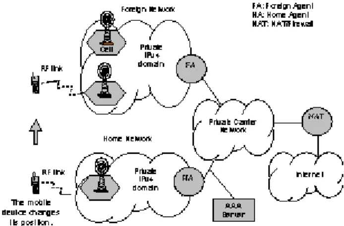
Mobile IP solves this problem by using a tunneling technique. In this approach, each mobile host has two IP addresses. One address is related to its “home network” (where the mobile host is registered), and does not change when the host changes its position. The second address is related to a “foreign network”, and changes each time the host attaches to a different physical network (refer to Figure 1). This second address is called COA (Care-Of Address).
The router attached to the mobile host at the foreign network is called “foreign agent” (FA). The router at the home network is called “home agent” (HA). The home agent is a special router, responsible for authenticating the mobile host, and keeping an internal table mapping the COA to the home IP address of every mobile host it serves.
Figure 1. Simplified representation of a mobile IP network
2.2 Using private addresses
Private IP addresses are defined by RFC 1918 [4]. The private IP addresses can be freely used inside a private network, but they are not routable through the Internet. The IP addresses reserved for private use are: 10.0.0.0/8, 172.16.0.0/16 and 192.168.0.0/16. Hosts with private IP addresses can exchange information with other hosts connected to the Internet “only” by using IP address translators such as Proxy or NAT (Network Address Translation) [6]. Many IP-enabled cellular networks operate nowadays using private IPv4 addresses. Figure 1 describes a typical scenario where the Mobile IP network is implemented using private addresses. This paper assumes the mobile IP clouds as being non-overlapped IPv4 domains connected by a private carrier network, i.e., the mobile hosts are uniquely addressable within the same carrier network. In this case, both the Home Address and the Care-Of Address are private IPv4 addresses. In a more complex scenario, the mobile clouds would be private domains connected by a public network. This scenario imposes additional problems to the Mobile IP standard and is treated by [27].
In the scenario illustrated by Figure 1, deploying the mobile IP clouds with private addresses does not impose any limitation for communications within the same carrier. A problem arises only when the mobile host requires to communicate through the Internet. In this case, a mediator such as NAT or Proxy is required to map the mobile host private Home Address to a public address. The operation principle for both, NAT and Proxy, is almost the same: they replace the private IP addresses in the packets delivered to the Internet by their own public IP addresses. Operating this way, they permit to use the same public IP address for several devices (in general, thousands of private IP addresses per public IP). An important limitation, however, is that a host with a private IP address can act only as a client, because its address is not visible by hosts outside the private network.
NAT is typically implemented on routers. A NAT device is usually seen as the default gateway for the hosts with private IP addresses (i.e. NAT is application transparent). NAT is almost independent of the application protocol transported by the IP packets. Just the protocols that transport the source address in the data field of the packet present some problems for NAT operation [6]. Basically, NAT can be implemented by two different mechanisms: with or without port (TCP/UDP) translation. When port translation is not implemented, the number of concurrent sessions is limited to the number of public IP addresses available. With port translation, in this case NAT is also named PAT (Port Address Translation) or NAPT (Network Address and Port Translation), a single public IP address can be used to support thousands of concurrent private IP
sessions. Theoretically, one public IP address can be used to map about 63K private IP addresses (the number of TCP/ UDP ports excluding well known ports), considering one connection per IP. In general, a NAT router uses a small poll of public addresses that allows to map hundreds of thousands private IP addresses [9].
A proxy is typically implemented as an application server. Therefore, a proxy is not client-transparent, because the traffic transmitted by the host must be explicitly redirected to the proxy. This inconvenient can be somewhat minimized by adopting the “Transparent Gateway Approach”. In this case, the default gateway is configured to redirect part of the network traffic to the proxy, eliminating the need of client reconfiguration. Proxies, however, have another important limitation. They are very resource consuming because they broke the client-server model, i.e., they can lead to expensive hardware in the case of carrier operators.
When using private IP addresses with NAT or Proxy one must consider that all mobile hosts will appear to other Internet hosts as being the “same computer”, because they will use the same IP address. Therefore, hosts with private IP addresses can’t be used as servers, because there’s no way to initiate a connection with them. This limitation can be somewhat minimized by implementing a NAT variant known as bi-directional or two-way NAT [9]. Bi-directional NAT is used in conjunction with a DNS extension, implemented as a DNS Application Level Gateway (DNS_ALG) [10]. In this mechanism, fully qualified domain names (FQDN) identify hosts with private IPv4 addresses. When an external host queries for a host name in a private network, DNS_ALG triggers a NAT session on a bi-directional NAT, mapping a public IPv4 address to the private host. This dynamic mapped IPv4 public address is then returned to the external host. It should be noted, however, that bi-directional NAT requires a pool of public IPv4 addresses. This solution is not intended to provide bi-directional addressing to a large number of IPv4 hosts, but instead, for just a selected number of host that are required to be externally addressed.
Private IPv4 addresses can be used without restriction for deploying WAP services because the WAP gateway can act as a Proxy for the mobile subscribers [8]. Commercial WAP Gateways include support to the “WAP Push” service, enabling to start a session with a mobile subscriber by using a phone number, an user name or a similar parameter as a unique identifier. However, WAP is not the only packet-data service that can be deployed over a cellular network. Tethered (i.e. the cellular is a modem for a portable computer) and non-WAP embedded applications need another mediator to access the Internet such as NAT or Proxy. The same reasoning applies to a mobile device connected to a WLAN.
and NAT/Proxy can’t be considered as long term solutions for deploying Mobile IP networks. New generation of applications, such as IP telephony and push applications, assume unique addressing and client “always on” reachability.
3 Transition Mechanisms
As stated in previous section, IPv4 private addresses allow deploying Mobile IP networks of virtually unlimited sized. However, hosts with private addresses can act only as clients, i.e., they can’t receive a message from a host they haven’t initiated a connection before. To overcome this limitation, this section will evaluate the use of Internet Protocol Version 6 (IPv6) addresses [5,11] as an alternative to the private IPv4 addresses mechanism. IPv6 is considered a real alternative for solving the IPv4 shortage-addressing problem because it can support a virtually unlimited number of devices, by introducing a 16-byte address space. However, IPv4 and IPv6 are not compatible. That means that adopting IPv6 will require changes in the existing infrastructure, including end user’s and network devices. To allow an immediate use of IPv6 over an existing IPv4 infrastructure, transition techniques should be employed [7].
Several transition mechanisms have already been published by IETF, and they are still under development. An overview of these transition mechanisms is presented in an IETF Internet Draft reviewed periodically [12]. There still no transition mechanism that could be used in any situation. Each transition mechanism intends to solve specific transition issues. In many situations, more than one transition mechanism should be used in order to allow proper communication between IPv4 and IPv6 hosts and routers [13].
As the work described in this paper is strongly based on the existing transition mechanisms, a summary of the most important mechanisms will be presented in this section. In order to facilitate the presentation of these mechanisms, they have been classified in 4 groups. The classification exposed here is for didactical purposes only; it is not employed by IETF. The four groups are: Dual-Stack Host Based Mechanisms, Translation Based Mechanisms, Transport Layer Based Mechanisms and Tunneling Based Transition Mechanisms. Next we present a summary of each group of mechanisms and a table comparing their main features.
3.1 Dual-Stack Host Based Mechanisms
The dual stack approach is a straight-forward way to assure the coexistence of IPv4 and IPv6 hosts. A dual stack host has both an IPv4 stack and an IPv6 stack implemented
in a multi-protocol network operating system. By selecting the proper socket interface, the application chooses the IPv6 or the IPv4 stack for network communication, i.e., a dual stack approach requires existent IPv4 applications to be rewritten using the IPv6 API [28].
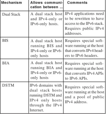
For avoiding this problem, two solutions have been proposed. The first one is named “Bump-In-The Stack”, or BIS for short [19]. The BIS mechanism has three main components, all of them integrated in the network operating system: an “extension name resolver”, an “address mapper” and a “translator module” based on SIIT (Stateless IP/ICMP Translation Algorithm) [20]. The BIS mechanism is triggered when an IPv4 application queries a DNS server that responds with an “AAAA record”. In this case, BIS maps a fake IPv4 address (from a fake IPv4 address pool) to the IPv6 address and returns it to the application. When the application sends the packet with the fake destination address, the BIS mechanisms triggers the translation module, replacing the IPv4 header by the IPv6 header with the mapped address. A similar procedure is triggered when an IPv4 application receives a packet from an IPv6 host. When the DNS server responds with an “A record”, no translation is applied.
Mechanism Allows communi- Comments cation between ...
Dual Stack A dual stack host and IPv4-only or IPv6-only hosts.
IPv4 applications need to be rewritten to have access to the IPv6 stack. Requires public IPv4 addresses.
BIS A dual stack host
running BIS and IPv4-only or IPv6-only hosts
Requires special soft-ware running at the host that converts IPv4 head-ers to IPv6 headhead-ers.
BIA A dual stack host
running BIA and IPv4-only or IPv6-only hosts
Requires special soft-ware running at the host that converts IPv4 APIs to IPv6 APIs.
DSTM IPv6 domains with
dual stack hosts running DSTM and IPv4 only hosts through the IPv4 Internet.
Requires special soft-ware running at the host and a pool of public IPv4 address.
Table 1: Dual-Stack Host Based Mechanisms.
A third approach named DSTM (Dual Stack Transition Mechanism) also uses a dual stack host [22]. This mechanism however focuses a different issue. It aims to allow dual stack hosts, connected to IPv6-only networks, to communicate to IPv4-only hosts in the Internet. For allowing this, an IPv4 over IPv6 (4over6) tunneling technique that encapsulates IPv4 packets in the payload of IPv6 packets is employed. The packets are sent to a DSTM gateway, located at the border of the IPv6 network, that decapsulates the IPv4 packets and deliver them through the Internet. In the DSTM approach, IPv4 addresses are not permanently allocated to the dual stack hosts. Instead, when a communication to an IPv4 only host needs to be established, a DSTM server allocates a temporary IPv4 address to the dual stack host.
Table 1 presents a summary of the Dual-Stack Host Mechanisms.
3.2 Translation-Based Mechanisms
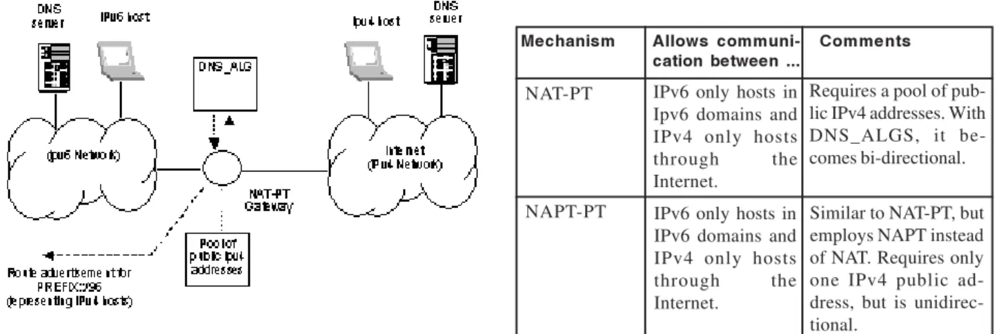
Translation-based mechanisms are similar to conventional NAT. But instead of mapping private to public addresses, they map IPv4 to IPv6 addresses. NAT-PT (Network Address Translation - Protocol Translation) is the most important example of translation-based mechanism [26]. It enables communication between IPv6-only hosts and IPv4-only hosts through the Internet. NAT-PT combines address mapping, protocol translation (SIIT) and a DNS_ALG in order to support a bi-directional communication between IPv4 and IPv6 hosts (see Figure 2). The DNS_ALG is an application specific agent that works in conjunction with the NAT-PT (which is application unaware). The DNS_ALG is capable of intercepting and triggering events based on DNS messages that traverses the NAT-PT gateway.
Figure 2. NAT-PT operation scenario.
In the NAT-PT approach, IPv4 hosts are represented by IPv6 addresses formed by adding a pre-configured prefix to their addresses (i.e., <PREFIX::/96><IPv4>). In order to make IPv6 hosts to properly address IPv4 hosts, the DNS_ALG intercepts incoming DNS responses of “A” records and replaces them by “AAAA” records, automatically adding the prefix. Also, the pre-configured prefix is advertised in the IPv6 domain by the NAT-PT gateway (see Figure 2). Therefore, only the packets with the pre-configured prefix are redirected to it.
A packet delivered from an IPv6 host to an IPv4 host follows this typical sequence: the IPv6 hosts sends a packet with the PREFIX::/96 added to the IPv4 address. The NAT-PT gateway has a pool of IPv4 public addresses. It maps the IPv6 address of the host (source address) to an IPv4 address from the pool, implements the IPv6-to-IPv4 protocol translation (using SIIT), and delivers the packet to the IPv4 host. When the NAT-PT gateway receives the packet returned by an IPv4 host through a session already established, it performs the reverse operation, i.e., converts the IPv4 header into an IPv6 header by retrieving the mapped address. In traditional NAT-PT only IPv6 hosts can initiate sessions. With bi-directional NAT-PT, sessions can be initiated from both IPv4 hosts and IPv6 hosts. Bi-directional NAT-PT is implemented as a bi-Bi-directional NAT by using DNS_ALG, as explained in section 2.2.
In order to avoid the requirement of a pool of public IPv4 addresses, a NAPT-PT (Network Address and Port Translation - Protocol Translation) approach can be employed. Similarly to NAPT, NAPT-PT allows sharing a single IPv4 public address among 63K simultaneous connections. NAPT-PT is always unidirectional (IPv6 to IPv4 hosts).
Table 2 presents a summary of the Translation Based Mechanisms.
Table 2: Translation Based Mechanisms
Mechanism Allows communi- Comments cation between ...
NAT-PT IPv6 only hosts in Ipv6 domains and IPv4 only hosts through the Internet.
Requires a pool of pub-lic IPv4 addresses. With DNS_ALGS, it be-comes bi-directional.
NAPT-PT IPv6 only hosts in IPv6 domains and IPv4 only hosts through the Internet.
3.3 Transport Layer Based Mechanisms
Similarly as a conventional proxy can map private to public IPv4 addresses operating above the network layer, transition mechanisms can also operate above the network layer. The most evident example of translation at the transport layer is the SOCKS64 proxy [23]. SOCKS64 proxy is an enhanced proxy that employs the same approach than the conventional SOCKS [24]. In fact, sites that already use SOCKS-aware clients can be easily updated to enable IPv4 hosts to connect to IPv6 hosts. For doing that, the SOCKS gateway is implemented as a dual IPv4/IPv6 stack host. SOCKS64 uses a DNS trick to enable IPv4 hosts to address IPv6 hosts: the SOCKS library, implemented in the client, intercepts DNS queries and responds them with fake IPv4 addresses. When the client calls the “connect API”, the SOCKS library replaces the fake IP by the original FQDN and delivers the IPv4 “socksified” packet to the proxy that performs the real DNS query. If the answer is an “AAAA record”, the proxy opens a socket to the destination IPv6 host using the IPv6 interface. Otherwise, it uses the IPv4 interface. SOCKS64 is a bi-directional solution because it enables IPv4 hosts open sessions with IPv6 hosts and vice-versa. However, the IPv4 addresses are supposed to be public. A problem with the socks approach is that it breaks the client-server model, i.e., the proxy internally maintains two sockets, and this may be a performance issue when the network is under huge traffic.
A second mechanism called Transport Relay Translator (TRT) operates in a similar way than SOCKS64 [25]. The straight-forward use of the TRT mechanism is to enable clients IPv6-only hosts to connect to servers IPv4-only hosts without any software modification. For doing that, TRT introduces in the network an intermediary device that acts as a transport relay translator that respond for all IPv6 addresses with a dummy prefix (say C6::/64) in an IPv6 network. In order to address an IPv4 host, an IPv6 host must build a fake IPv6 address by adding the dummy prefix to the IPv4 address of the destination host (the RFC suggests to modify the client DNS resolver or to build a special DNS implementation in order to resolve IPv4 names with the dummy prefix). Consequently, the transport relay intercepts all traffic addressed to IPv4 hosts.
Similarly as the SOCKS64 mechanism, the TRT opens an IPv4 TCP connection or sends UDP IPv4 datagrams to the IPv4 destination. Theoretically, TRT can also be employed to permit IPv4 hosts to initiate connections to IPv6 hosts, by using temporary mapped IPv4 addresses on the IPv6 side, as implemented in the NAT-PT. TRT also breaks the client server model.
Table 3: Transport Layer Based Gateway Mechanisms
Mechanism Allows communi- Comments cation between ...
SOCKS64 IPv4 or IPv6 only hosts running a SOCKS LIB.
Requires special soft-ware running at the host. Breaks the client-server model. Acts at the API level.
TRT IPv6 only hosts to
IPv4 only hosts.
Requires some sort of DNS modification. Breaks the client-server model.
Table 3 presents a summary of the Transport Layer Based Gateway Mechanisms.
3.4 Tunneling Based Mechanisms
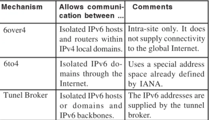
The tunneling transition mechanisms support connectivity of isolated IPv6 hosts or domains without a full IPv6 network infrastructure. The basic solution consists in encapsulating IPv6 packets inside IPv4 payloads. IETF has proposed several tunneling solutions. The three most common examples of tunneling based mechanisms are 6over4, 6to4 and Tunnel Broker (see Table 4).
The 6over4 mechanism [18] is a site local transition mechanism also known as “virtual Ethernet”. It permits isolated IPv6 hosts and routers to communicate within an IPv4 network. Because IPv6 networks are strongly based on multicast messages, the 6over4 mechanism defines a mapping between IPv6 and IPv4 multicast groups. These IPv4 multicast groups are used for Neighbor Discovery and stateless address configuration.
The 6to4 mechanism [16,17] permits to interconnect IPv6 isolated networks through the legacy Internet (IPv4). The idea is to embed IPv4 tunnel addresses into the IPv6 prefixes so that any domain border router can automatically discover the tunnel endpoints for outbound IPv6 traffic. The 6to4 mechanisms is used in this paper for implementing the “Transparent IPv6” approach, and thus, it is presented in detail in section 5.
Table 4: Tunneling Based Transition Mechanisms
Mechanism Allows communi- Comments cation between ...
6over4 Isolated IPv6 hosts and routers within IPv4 local domains.
Intra-site only. It does not supply connectivity to the global Internet.
6to4 Isolated IPv6
do-mains through the Internet.
Uses a special address space already defined by IANA.
Tunel Broker Isolated IPv6 hosts or domains and IPv6 backbones.
A third tunneling based solution proposed by IETF is called Tunnel Broker [14]. The Tunnel Broker approach automates the process of creating tunnels for connecting isolated IPv6 hosts or isolated IPv6 domains to IPv6 backbones through the Internet. The Tunnel Broker defines a client-server model. The client of the Tunnel Broker service is a dual-stack IPv6 node (host or router) connected to the IPv4 Internet. The server side has two components: a Tunnel Broker and one or more Tunnel Servers. The Tunnel Servers are dual-stack routers connected to the global Internet and to IPv6 backbones. They are the end points of the tunnels. The Tunnel Broker role is to receive the requests from the clients and redirect them to the appropriate Tunnel Server by returning the configuration information for creating the tunnel. The IPv6 addresses used in both sides of the tunnel are supplied by the Tunnel Broker.
4. Mobile Networks and Transition Mechanisms
Transition Mechanisms are already considered an important alternative for implementing large mobile networks. For example, the 3GPP (3G Partnership Project) has specified the use of IPv6 and defined several scenarios where transition mechanisms would be useful [3].
In a first scenario, mobile devices are dual-stack hosts connected to mobile networks with both IPv4 and IPv6 support. Here, dual-stack transition mechanisms, such as BIS or BIA, permit the reuse of existing IPv4 applications. Considering the IPv4 address shortage problem, BIS and BIA have a strong disadvantage of requiring public IPv4 addresses when the dual-stack host uses the IPv4 stack. In this scenario, DSTM would be a more interesting solution because it permits to deploy an IPv6-only mobile network and offers a mechanisms for temporarily allocating IPv4 public addresses to mobile hosts when required.
In a second scenario, mobile devices are IPv6-only hosts in isolated IPv6 mobile domains connected to the IPv4 Internet. In this case, NAT-PT could be used to permit the mobile hosts to access IPv4 hosts in the Internet. NAT-PT has the disadvantage of requiring a pool of public IPv4 addresses. NAPT-PT does not require a pool of addresses but is unidirectional. The transport layer based mechanisms such as SOCKS64 and TRT could also be considered. However, these mechanisms are very resource consuming because they break the client-server model.
A third scenario would also have IPv6-only mobile devices in isolated IPv6 mobile domains connected to the IPv4 Internet. The issue here, however, is to permit the communication between the IPv6-only hosts through the Internet. That’s is the typical scenario for tunneling based transition mechanisms such as 6to4 and Tunnel Broker. The 6to4 mechanism is more suited for building IPv6
extranets over the legacy Internet. The Tunnel broker offers a better solution for connecting isolated IPv6-hosts or domains to an IPv6 backbone.
The solution proposed in this paper considers a fourth scenario where the mobile devices are legacy IPv4 hosts that cannot be upgraded to support dual-stack or IPv6. In this scenario, the mobile networks are private IPv4 domains connected to the IPv4 Internet. The basic idea is to use IPv6 address as global unique identifiers to hosts with private IPv4 addresses. As seen before, transition mechanisms can be used to map IPv4 addresses to IPv6 addresses, in many cases without software modification. Tunneling techniques permit to transport IPv6 packets through the legacy IPv4 Internet. By combining these solutions, this paper proposes a technique that acts at the same time as a transition mechanism, allowing communication between IPv4 and IPv6 hosts, but also as a solution to address hosts with private IPv4 address from the Internet.
The solution proposed in this paper is strongly based on the 6to4 transition mechanism exposed in the next section. A transparent gateway similar to NAT-PT integrated with DNS-ALG is also employed.
5 Dynamic tunnels with the 6to4 mechanism
The 6to4 transition mechanism allows transporting IPv6 packets in the payload of IPv4 packets using dynamic tunnels. This mechanism does not work with any IPv6 addresses. IANA has reserved a specific block of IPv6 addresses for supporting this mechanism. Before explaining how it can be done, it is convenient to examine how the IPv6 address space is organized [11].
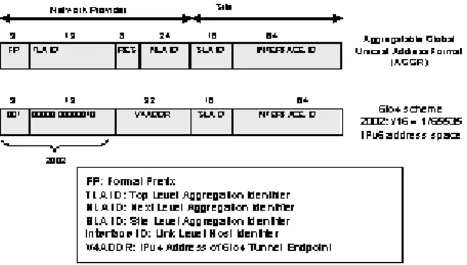
The IPv6 address space has been segmented in order to support different types of addresses. The leading bits in the address indicate the specific type of an IPv6 address. The variable-length field comprising these leading bits is called the Format Prefix (FP). Most of the IPv6 address
space is still unassigned. However, one important segment of addresses called AGGR - “Aggregatable Global Unicast” - has been already defined. This segment represents 1/8 of the full IPv6 address space. An AGGR address have a standard format, as shown in Figure 3. Please refer to [15] to an accurate description of the AGGR address fields.
The TLA (Top Level Aggregation Identifier) field is used to segment the AGGR address space into smaller blocks. That permits IANA to allocate blocks of AGGR addresses to specific entities. IANA is supposed to assign these blocks to IPv6 Autonomous Systems that offer transit traffic, such as huge backbones. However, IANA reserved one TLA block to a special address scheme called 6to4. Its numeric value is 0x0002, i.e., 2002::/16 when expressed as an IPv6 address. Figure 3 also shows the 6to4 scheme address format. The 6to4 scheme permits the creation of dynamic tunnels intended to transport IPv6 packets over an existing IPv4 infrastructure. Figure 4 explains this principle.
Figure 4. Dynamic tunnels with 6to4 scheme.
To implement the 6to4 scheme, an IPv6 network must have at least one public IPv4 address, referred as V4ADDR. The V4ADDR is the IPv4 address of the router interface that connects the IPv6 network to the Internet. The other router interface, attached to the IPv6 network, has an IPv6 address. This router (referred as 6to4 router) must support the 6to4 addressing scheme by dynamically tunneling the IPv6 packets forwarded to the Internet [16,17]. The tunneling technique consists in encapsulating an IPv6 packet in an IPv4 packet using the IPv4 protocol type 41, as defined in the Transition Mechanisms, RFC 2893 [7]. The 6to4 router can discover the 6to4 tunnel endpoint by checking the V4ADDR field from the IPv6 destination address. This enables the router to dynamically create the tunnel without previous configuration. The 6to4 tunnels are stateless, because all information required for creating the tunnels is extracted from the packets.
7 Transparent IPv6 Mechanism
This section presents a mechanism for assigning IPv6 addresses to IPv4 devices without any hardware or software modification. This mechanism is called in this paper “Transparent IPv6” (TIP6, for short). The TIP6 mechanism is a combination of the IETF 6to4 tunneling mechanism and a translation based mechanism. The main idea is to provide the benefits of IPv6 addressing without introducing changes in the existing IPv4 infrastructure. In fact, this mechanism could be immediately employed in Mobile IP networks for assigning IPv6 addresses to existing mobile devices without any software modification.
7.1 6to4 Address Mapping
In the TIP6 mechanism, mobile hosts with private IPv4 addresses are mapped to IPv6 addresses as shown in Figure 5. The IPv6 address belongs to the TLA block 2002::/16, in accordance with the 6to4 scheme. The interface identifier field is defined using the IPv4 address as the lower order 32 bits. Even though there is no restriction imposed to the identifier in the TIP6 mechanism, the higher order 32 bits of the interface identifier are kept zero to conform to existing standards [18]. For most implementations, SLA ID can also be kept equal to zero. The SLA ID field will be required only for very large networks that have overlapped private IPv4 address spaces.
The IPv4 hosts are addressed using Fully Qualified Domain Names (FQDN). IPv4 hosts must have their names registered in a DNS server using IPv6 AAAA records. For example, a host with IP 10.1.2.3 should have an AAAA record mapping its name to 2002:<V4DDR>::<10.1.2.3>. Note that the mapped IPv6 address is a global identifier that can be used by external hosts to uniquely address any host in the network.
Figure 5. IPv6 address mapping to IPv4 addresses in TIP6 mechanism.
7.2 Operation Description
Lets consider two scenarios in order to describe the operation of the TIP6 mechanism.
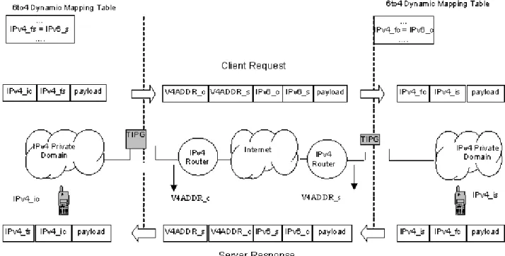
The first scenario (Figure 6) shows a private IPv4 domain and an IPv6 domain (more precisely, a 6to4 domain) connected by the global Internet. The key element in the TIP6 mechanism is the “Transparent 6to4 Gateway” (TIPG, for short). The TIPG is a dual homed host developed specifically for supporting our proposal. One interface of TIPG is configured with a private IPv4 address. The other interface must have a public registered IPv4 address, used as the V4ADDR for creating dynamic tunnels with 6to4 standard compatible routers or other TIPG gateways. Besides creating the 6to4 tunnels, TIPG is responsible for dynamically assigning temporary IPv4 addresses to represent IPv6 hosts in foreign networks. To configure the TIPG, the network administrator must define an “IPv4 Foreign Address Pool”, with private IPv4 addresses that are not used in the internal network. Because the mapping is not permanent, the pool size defines the number of concurrent sessions that can be handled by the TIPG. The TIPG must be configured also as a DNS server for the mobile hosts. When TIPG receives a DNS query from an internal client, it maps a temporary IPv4 address representing the foreign IPv6 server (i.e., similar to a DNS_ALG, but TIPG does not intercept all packets in the network). This IPv4 address is returned to the internal client that builds a simple IPv4 packet and delivers it to the network. TIPG requires to intercept only the packets which destination address belongs to the foreign address pool.
In the scenario of Figure 6, the IPv4-only hosts address the IPv6 only hosts using temporarily mapped addresses from a foreign address pool configured in the TIPG. The IPv6-only hosts address the IPv4-only hosts using the IPv6 mapped address as shown in the Figure 5.
Figure 6. Transparent IPv6 (TIP6) First Scenario.
The second scenario (Figure 7) shows two private IPv4 domains connected by the global Internet. This scenario is similar to the previous one because the hosts with private IPv4 addresses are seen by the foreign world as “virtual” IPv6 hosts. Then, the hosts in domain A address the hosts in domain B using temporarily mapped addresses from the foreign address pool configured in the TIPG in domain A.
Figure 7. Transparent IPv6 (TIP6) Second Scenario.
Similarly to NAT, TIPG keeps an internal table mapping foreign IPv6 addresses to dynamically assigned private IPv4 address. Figure 8 illustrates this mapping table. Note that both, “true” IPv6 hosts and “mapped” IPv6 hosts are seen by internal IPv4-only hosts as IPv4 hosts with addresses belonging to the foreign address pool.
When transmitting, TIPG performs two sequential op-erations on each packet. First, it converts the IPv4 packet into an IPv6 packet using a NAT-PT approach. Second, it tunnels the packet adding an IPv4 header. These
tions are illustrated in Figure 9. At the foreign network a similar operation is performed. The TIPG in the destination network de-tunnels the incoming packet and performs a NAT-PT operation, building an IPv4 packet with an IPv4 private address temporarily mapped to the client’s IPv6 address. The reply from the server is also illustrated in Figure 8.
Figure 9. Translation and tunnelling in TIP6.
Symbol Description
IPv4_ic: Internal client private IPv4 address.
IPv4_fs: IPv4 address temporarily mapped to the address of the foreign server.
IPv6_s: IPv6 address of the foreign server (found by DNS resolution).
IPv6_c: IPv6 address of the internal client (built by combining the Ipv4 address and V4ADDR).
IPv4_is: Internal server private IPv4 address.
IPv4_fc: IPv4 address temporarily mapped to the IPv6 address of the foreign client.
V4ADDR_c: IPv4 address of the TIPG in the client’s network.
V4ADDR_s: IPv4 address of the TIPG in the server’s network.
Table 5: Legends for Figure 9.
The symbols used in Figure 9 are explained in Table 5. 7.3 Algorithms
Figure 10 describes the procedure in the TIP6 approach when an IPv4 host sends a packet to a foreign IPv6 host. There are two situations to consider: the internal IPv4 is a client initiating a communication with an IPv6 foreign server; or the internal IPv4 host is a server answering a request from an IPv6 foreign client. Observe that, in this last situation, the mapping table is updated when the requisition arrives from the foreign host.
Figure 11. Procedure for receiving a packet in TIP6 .
8 Transparent IPv6 in Mobile Networks
This section explains how the “Transparent IPv6” (TIP6) can be used to deploy very large wireless networks without IPv4 provisioning. As seen in the previous sections, the TIP6 mechanism permits to assign IPv6 addresses to IPv4 hosts without modifying existing user’s devices or network elements. TIP6 is implemented in a wireless network by connecting a “Transparent 6to4 Gateway” (TIPG) to the home agent, as show in Figure 12. In this configuration the TIPG must be configured as the DNS server for the mobile devices, but not the default gateway. The default gateway is the foreign agent, as specified by the Mobile IP standard. The TIP6 mechanism requires an additional route to be configured in the home agent. This route directs all
packets with destination addresses belonging to the foreign address pool to the TIPG. All other packets can be delivered directly to the firewall.
Figure 12. Carrier Networks interoperation using TIP6.
All examples given previously assume that the IPv6 network is implemented using the 6to4 address space. However, RFC 3056 [17] defines also the figure of a “router relay”. A router relay is a 6to4 router configured to support transit routing between 6to4 addresses and native IPv6 addresses. Future works are required to evaluate the use of router relays with the TIP6 mechanism in order to permit addressing any type of IPv6 domains.
9 Conclusion
This paper presented a new mechanism to manage the problem of shortage of globally unique IPv4 addresses for Mobile IP. This mechanism is called “Transparent IPv6” (TIP6, for short). The main idea is to provide the benefits of IPv6 addressing without introducing significant changes in the existing IPv4 infrastructure. The TIP6 mechanism is a combination of the IETF 6to4 tunneling mechanism and a translation based mechanism. We have shown that the TIP6 mechanism extends the standard NAT functionalities by permitting a mobile host to receive connections from other mobile or fixed hosts connected to the Internet. An IPv4 host in a TIP6 network can communicate with other TIP6 networks or with “true” IPv6 hosts using the 6to4 addressing scheme. This feature will permit the coexistence of emerging IPv6 Mobile IP implementations with legacy IPv4 Networks. Future works are required to evaluate the use of 6to4 relay routers with TIP6, in order to permit addressing native IPv6 domains.
References
[1] C. Perkins, ed., IP Mobility Support, IETF RFC 2002, Oct. 1996.
[2] Salkintzis, A.K.; Fors, C.; Pazhyannur, R., WLAN-GPRS integration for next-generation mobile data networks, IEEE Wireless Communications, Vol. 9, Oct. 2002, pp.112-124.
[3] J. Soininen , J. Wiljakka, A.Durand , P. Francis, “Transition Scenarios for 3GPP Networks”, IETF Internet Draft, Abr. 2002.
[4] Y. Rekhter, B. Moskowitz, D. Karrenberg, G. J. de Groot , E. Lear, “Address Allocation for Private Internets”, IETF RFC 1918, Febr. 1996.
[5] S. Deering and R. Hinden, Internet Protocol, Version 6 (IPv6) Specification, IETF RFC 1883, Dec. 1995.
[6] Egevang, K. and P. Francis, “The IP Network Address Translator (NAT)”, IETF RFC 1631, May 1994.
[7] R. Gilligan, E. Nordmark, Transition Mechanisms for IPv6 Hosts and Routers, IETF RFC 2893, Aug. 2000.
[8] WAP Push Architectural Overview, WAP Forum Technical Specifications, Version 03, July 2001.
[9] P. Srisuresh, M. Holdrege, “IP Network Address Translator (NAT) Terminology and Considerations”, IETF RFC 2663, August 1999.
[10] P. Srisuresh, G. Tsirtsis, P. Akkiraju, A. Heffernam, “DNS extensions to Network Address Translators (DNS-ALG)”, IETF RFC 2694, Sept. 1999.
[11] R. Hidden, S. Deering. IP Version 6 Addressing Architecture. IETF RFC 2373, July 1998.
[12] D. Finkerson, A. Hazeltine, M. Kaat, T. Larder, R. van der Pol, Keio Univ., Y. Sekiya, Keio Univ. H. Steenman, G. Tsirtsis, “An overview of the introduction of IPv6 in the Internet”, IETF Internet Draft, Feb.2002.
[13] A. Baudot, G. Egeland, C. Hahn, P. Kyheroinen, A. Zehl, “Interaction of Transition Mechanisms”, IETF Internet Draft, Febr. 2002.
[14] A. Durand, P. Fasano, I. Guardini, D. Lento, “IPv6 Tunnel Broker”, IETF RFC 3053, Jan. 2002.
[15] R. Hidden, M. O’Dell, S. Deering. An IPv6 Aggregatable Global Unicast Address Format. IETF RFC 2374, July 1998.
[16] B. E. Carpenter, K. Moore, B. Fink. Connecting IPv6 Routing Domains Over the IPv4 Internet. Cisco Internet Protocol Journal, Volume 3, Number 1, March 2000.
[17] B. Carpenter, K. Moore, “Connection of IPv6 Domains via IPv4 Clouds”, IETF RFC 3056, Feb. 2001.
[18] B. Carpenter, C. Jung, “Transmission of IPv6 over IPv4 Domains without Explicit Tunnels”, IETF RFC 2529, March 1999.
[20] E. Nordmark, “Stateless IP/ICMP Translation Algorithm (SIIT)”, IETF RFC 2765, Feb. 2000.
[21] M. Shin, Y. Kim, E. Nordmark, A. Durand, “Dual Stack Hosts using ‘Bump-in-the-API’ (BIA)”, IETF RFC 3338, Oct. 2002.
[22] J. Bound, L. Toutain, O. Medina, F. Dupont,H. Affifi, A. Durand, “Dual Stack Transition Mechanism (DSTM)”, IETF Internet Draft, Jan. 2002.
[23] H. Kitamura, “A SOCKS-based IPv6/IPv4 gateway mechanism”, IETF RFC 3089, April 2001.
[24] M. Leech, M. Ganis, Y. Lee, R. Kuris, D. Koblas and L. Jones, “SOCKS Protocol Version 5”, March 1996.
[25] J. Hagino, K. Yamamoto, “An IPv6-to-IPv4 transport relay translator”, RFC3142, June 2001.
[26] G. Tsirtsis, P. Srisuresh, “Network Address Translation - Protocol Translation (NAT-PT)”, IETF RFC 2766, Feb. 2000.
[27] H. Levkowetz , S. Vaarala , “Mobile IP NAT/NAPT Traversal using UDP Tunnelling”, IETF Internet Draft, Nov. 2002.