PRODUCTION OF ALUMINIUM BASED COMPOSITES
REINFORCED WITH EMBEDDED NiTi BY FRICTION
STIR WELDING
Luís Gonçalves Mendes
Dissertação para a obtenção do grau de Mestre em
Engenharia Mecânica
Orientadora: Professora Doutora Rosa Maria Mendes Miranda,
Faculdade de Ciências e Tecnologia
Co-orientador: Professor Doutor Telmo Jorge Gomes dos Santos,
Faculdade de Ciências e Tecnologia
i
AGRADECIMENTOS
Gostaria de expressar minha gratidão a todos aqueles que, de alguma forma, estiveram envolvidos nesta investigação, sem os quais teria sido impossível apresentar este trabalho.
À Professora Rosa Miranda a minha mais profunda gratidão, por me convidar para este desafiador e pioneiro projeto, pelo apoio dado, pelo interesse despertado e tempo investido e pelos conhecimentos transmitidos ao longo deste curso.
Ao meu co-orientador o Professor Telmo Santos pelo seu apoio e trabalho em domínios cruciais para o desenvolvimento desta investigação.
Ao Professor Pedro Vilaça pelas instalações e suporte técnico durante o trabalho experimental na STM IST.
Também, a minha gratidão para com o Professor Pamies Teixeira pelo seu aconselhamento muito bem-vindo.
À Professora Raquel Brás pelo seu interesse e apoio, nos ensaios de vibração.
Gostaria de agradecer ao Professor Braz Fernandes por todo o seu apoio, tempo investido, interesse e pelo material fornecido. Bem como ao Professor Mahesh e Professor Alexandre Velhinho.
À Professora Virgínia Infante pelo apoio técnico e caracterização mecânica realizada no IST.
A minha profunda gratidão ao Mestre João Gandra pela total disponibilidade e energia, sem a qual, não teria sido possível realizar este trabalho. Acima de tudo, pelo apoio e amizade.
Ao Sr. António Campos e Sr. Paulo Magalhães para a sua assistência e amizade.
Um agradecimento especial à minha família e amigos, que a seu modo, foram cruciais para a elaboração deste trabalho.
iii
AKNOWLEDGMENTS
I would like to express my gratitude to those who, in any way, were involved in this investigation, without whom it would have been impossible to present this work.
To Professor Rosa Miranda my deepest gratitude, for inviting me to such a challenging and pioneer project, for the support given, interest and time invested, as well as, the knowledge shared along this master course.
To my co-supervisor Professor Telmo Santos for his support and work various fields of this thesis.
To Professor Pedro Vilaça for the facilities and technical support during the experimental work at STM-IST:
Also my gratitude to Professor Pamies Teixeira for his advisory.
To Professor Raquel Almeida for her interest and support in the vibration tests.
I would like to thank Professor Braz Fernandes for all his support, time invested, interest and for the necessary material, as well as, to Professor Mahesh and Professor Alexandre Velhinho.
To Professor Virgínia Infante for the technical support in mechanical characterization performed at IST.
My deep gratitude to Master João Gandra for his availability, without which, it would have not been possible to perform this work. Above all for his friendship and support.
To Mr. António Campos and Mr. Paulo Magalhães for their assistance and friendship. A special appreciation to my family and friends, whom in their own special way were crucial for the accomplishment of this work.
v
RESUMO
As ligas de alumínio têm sido amplamente utilizadas em materiais compósitos de modo a promoverem uma melhoria das suas propriedades enquanto reduzem o peso. Na produção de compósitos com uma grande diferença de propriedades mecânicas e termofísicas a soldadura por fusão, devido às elevadas temperaturas, aumenta a formação de intermetálicos indesejáveis. Essas limitações têm levado ao estudo de processos de ligação no estado sólido, como a soldadura por fricção linear (SFL), para unir diferentes materiais.
Neste trabalho estudou-se a possibilidade de criar compósitos de ligas da série AA 1XXX reforçados com NiTi por SFL. Foram investigadas diferentes formas do material de reforço, analisadas as interfaces e os fluxos de material resultantes e caracterizados os compósitos produzidos. Observou-se um aumento de 70% da tensão de ruptura, em relação ao substrato de Al e a ligação entre os dois materiais dissimilares suporta tensões superiores às da ruptura do Al numa junta sobreposta. O compósito produzido apresenta uma conductividade eléctrica de cerca de 62 % IACS, reduzindo menos de 3% IACS em relação à do substrato de Al. Produziu-se assim um compósito com uma forte ligação mecânica entre ambos os materiais, mantendo as propriedades funcionais do NiTi e eléctricas do Alumínio.
PALAVRAS-CHAVE
Compósitos de matriz metálica Soldadura por friccção linear Ligação soldada
vii
ABSTRACT
Aluminium alloys have been widely used in composite materials in order to promote an enhancement in its properties while reducing weight. As in the production of new composites with a significant difference in mechanical and thermo-physical properties fusion welding processes enhances the formation of undesired intermetallics. Those limitations have driven research on solid state technologies, such as Friction Stir Welding (FSW), for joining dissimilar materials.
This study aimed to develop composites in AA 1XXX series aluminium alloys with NiTi by FSW. Different reinforcing material shapes were investigated, analyzed the interfaces and the resulting material flow. The final product was mechanically characterized. It was observed an increase of 70 % of ultimate tensile strength, compared to Al base material and yielding between the two dissimilar materials was greater than the Al lap joint yield stress. The final composite depicted a good electrical conductivity, reducing less than 3 % IACS of the Al base material. Thus, a composite with a strong mechanical bonding was produced, maintaining the original functional properties of the reinforcement NiTi alloy, and the electrical properties of the Aluminium.
KEY-WORDS
Metal matrix composite Friction stir welding Joining
ix
TABLE OF CONTENTS
AGRADECIMENTOS ... i
AKNOWLEDGMENTS ... iii
RESUMO ... v
PALAVRAS-CHAVE ... v
ABSTRACT ... vii
KEY-WORDS ... vii
TABLE OF CONTENTS ... ix
FIGURE LIST ... xii
TABLE LIST ... xvi
GLOSSARY OF ACRONYMS AND SYMBOLS... xvii
1. INTRODUCTION ... 1
1.1. Motivation ... 1
1.2. Objectives ... 2
1.3. Structure ... 2
2. STATE OF THE ART ... 3
2.1. Composite Materials ... 3
2.2. Shape memory alloys for composite damping enhancement ... 8
2.3. Manufacturing processes ... 12
2.4. Friction stir welding ... 15
2.5. Conclusions ... 23
3. EXPERIMENTAL PROCEDURE ... 25
3.1. Materials ... 25
3.2. Equipment ... 27
3.3. Working methodology ... 31
3.3.1. Sample preparation ... 31
x
3.3.3. FSW of aluminium lap joints with reinforcing materials ... 35
3.4. Characterization methodology ... 36
3.4.1. Visual and X-ray radiography inspection ... 37
3.4.2. Metallography ... 37
3.4.3. Mechanical Testing ... 38
3.4.4. Eddy currents testing ... 42
3.5. Conclusions ... 43
4. RESULTS AND DISCUSSION ... 45
4.1. Base and reinforcing material ... 45
4.2. FSW lap joint of AA 1100 without reinforcements ... 47
4.2.1. The impact of tool penetration on surface weld beads ... 47
4.2.2. Multi-pass in AA 1100 lap joints ... 53
4.2.3. Effect of the tool lift-off ... 57
4.2.4. Tensile testing... 60
4.2.5. Bending testing ... 61
4.2.6. Summary conclusions ... 63
4.3. FSW lap joints of AA 1100 with reinforcing materials ... 64
4.3.1. The impact of reinforcements on the material flow ... 71
4.3.2. Scanning electron microscope and energy dispersive X-ray spectroscopy .. 78
4.3.3. Tensile testing... 84
4.3.4. Bending testing ... 87
4.3.5. Vibration testing ... 88
4.3.6. Eddy currents testing ... 92
4.3.7. Summary conclusions ... 95
5. CONCLUSIONS AND SUGGESTIONS FOR FUTURE WORK ... 97
xii
FIGURE LIST
Figure 2.1 – Representative chart of engineering domains incorporating composite materials. ... 4
Adapted from [2, 3, 5] ... 4
Figure 2.2 – Comparison between conventional bulk materials and composite materials [1]. ... 4
Figure 2.3 – Classification scheme for the various composite types. ... 5
Figure 2.4 – Young modulus plotted against density for various engineering materials [7]. ... 6
Figure 2.5– SEM image of a tungsten wire at composite fracture [10]. ... 7
Figure 2.6 – (a) A β phase crystal. (b) Self-accommodating, twin-related variants A, B, C, and D, after cooling and transformation to martensite. (c) Variant A becomes dominant when stress is applied [11]. ... 8
Figure 2.7 – Binary Ti-Ni alloy phase diagram [16]. ... 9
Figure 2.8 – DSC measurement of a NiTi alloy with a Ti content of 50 at.% [17]... 9
Figure 2.9 – Comparison of free-decay damping curves at low frequencies (~5Hz) for mild steel and for Zn-Al HIDAMETS [18]. ... 10
Figure 2.10 – Geometry of the principle of the method for passing through critical speeds. W –amplitude, ω– natural frequency, OABCD path of the SMA designed response curve, dashed lines resonance zone. ... 11
Figure 2.11 – Steps in a hollow air-cooled blade, made of tungsten fiber reinforced superalloy, fabrication process [1]. ... 13
Figure 2.12 – Illustration of butt (left) and lap (right) joint configurations: tool traverse and rotation movements depicted above. ... 15
Figure 2.13 – Illustration of the four main zones in a transversal section of a friction stir welded bead. SZ – stirred zone, TMAZ – thermo-mechanically affected zone, HAZ – heat-affected zone, BM – base material, AS – advancing side, RS – retreating side. ... 16
Figure 2.14 – Diagram of FSP operating parameters. ... 17
Figure 2.15 – Plunge depth – PD (FSP parameter); a) Schematic illustration of PD, b) Effect of the PD variations from 0.15 mm to 0.4 mm in the right, rotational and traverse speeds were 900 rev/min and 63 mm/min, respectively [39]. ... 18
Figure 2.16 – Lap weld defects showing hooking on advancing side and plate thinning on retreating side in lap welds between AA 7075 (upper) and AA 2024 (lower) alloys [51]. ... 20
Figure 2.17 – Illustration of hooking and thinning effects after FSW, te and to indicators for the percentage effective thickness measurement. ... 21
xiii
Figure 3.1 – Stress-strain curve of NiTi after heat treatment at 500 ºC for 20 minutes. ... 26
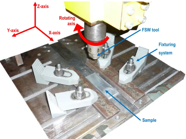
Figure 3.2 – Sample set up and degrees of freedom in FSW machine. ... 28
Figure 3.3 – Patented modular tool, (a) section view of the entire piece, (b) section view of the pin and shoulder [70]. ... 29
Figure 3.4 – FSW used tool, 18 mm diameter plain shoulder with one two-lap ridge, and a 5 mm diameter threaded cylindrical pin. ... 29
Figure 3.5 – Fixturing equipment, a) group of plates with a maximum of aperture, b) clamping system on worktable of the FSW equipment... 30
Figure 3.6 – Cross sections of base plate with metallic reinforcements before FSW. a) “V” type cross section shape groove, b) round cross section shape, opened with a 1,0 mm diameter steel wire, c) round cross section shape, opened with a 0,8 mm diameter steel wire, d) rectangular 1,1 x 3,5 mm cross section. ... 31
Figure 3.7 – FSW lap-joint with a threaded flat bottom 1.8 mm height pin. ... 33
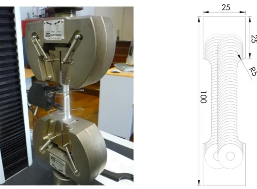
Figure 3.8 – Tensile runs set-up and composite test samples dimensions. ... 39
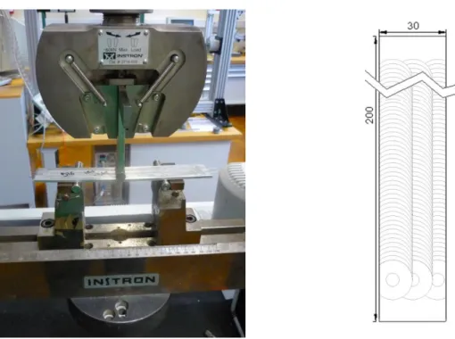
Figure 3.9 – Bending runs set-up and composite test samples dimensions. ... 40
Figure 3.10 – Experimental set-up of fixed-free constrained composite beam for vibration testing. ... 40
Figure 3.11 – Testing of sample D13 after being cooled for 2 minutes in liquid nitrogen. ... 41
Figure 3.12 – Left– example of FSWed sample with NiTi reinforcements, after multi-pass milling at different thicknesses; (1 – 0,7 mm; 2 – 0,5 mm; 3 – 0,3 mm; 4 – 0,1 mm). Right – experimental set-up of NiTi reinforced pass no. 4 with X–Y device. ... 42
Figure 4.1 – As-received AA 1100 cold hardened and partially annealed, section parallel to rolling direction ... 45
Figure 4.2 – Stress-strain curve of AA 1100 aluminium alloy... 46
Figure 4.3 – Stress-strain curve of NiTi alloy N. ... 46
Figure 4.5 – Stress-strain curve of NiTi after heat treatment at 500 ºC for 20 minutes and FSW in AA 1100 composite. ... 47
Figure 4.6 – Sample produced with -1.60 mm PD and traverse and rotational speeds of 50 mm/min and 800 rev/min, respectively. ... 48
Figure 4.7 – Cross section of AA 1100 lap jointed by FSW with -1.4 mm PD. ... 50
Figure 4.8 – Cross section of aluminium lap jointed by FSW with -1.5 mm PD. ... 51
Figure 4.9 – Cross section of aluminium lap jointed by FSW with -1.6 mm PD. ... 52
Figure 4.10 – details of surfaces weld beads overlapping by the AS (a) an by the RS (b). ... 53
xiv
Figure 4.12 –Cross section of overlapping aluminium lap jointed by FSW. v = 80 mm/min; ω =
800 rev/min; PH = 1.64 mm; PD = -1.65 mm; Force control = 1800 KN ... 56
Figure 4.13 – Shoulder distance to samples surface. From 51 to 99 shoulder distance was kept the same. (see annex A for more information about in testing parameters) ... 57
Figure 4.14 – Aluminium lap joint tensile test samples; (a) overlapping FSW by the AS, from left to right, untested sample, 1800 KN axial force FSW tested sample, 2000 KN axial force FSW tested sample; (b) detail of 2000 KN sample, (c) detail of 1800 KN sample. ... 60
Figure 4.15 – Tensile testing stress-strain curves of D22 ( at 800 rev /min, 80 mm/min and 1800 KN), D6 ( at 800 rev /min, 80 mm/min and 2000 KN) and base material. ... 61
Figure 4.16 – Aluminium lap joint bending test samples; (a) general view of the bent samples at the maximum angle of 44 º, (b) detail view of deformed thickness due to compressive stresses, (c) close-up of the tensile region, no failure is depicted, left (D12) and right (D14). ... 62
Figure 4.17 – Bent testing of samples D14 and D12, Flexture stress-strain curve. ... 63
Figure 4.18 – detail of preformed groove using a hydraulic press, prior to positioning the reinforcing materials. ... 64
Figure 4.19 – Detail on the remnant wire after positioning the ribbons onto the material matrices. ... 65
Figure 4.20– Ribbon wave shape, a) surface wave features, b) top view of the weld bead in X-ray radiography, c) longitudional view of the volume weld in X-X-ray radiography. ... 65
Figure 4.21 – Macrographs of cross section 1 depicted in figure 4.20. ... 66
Figure 4.22 – Macrographs of cross section 2 depicted in figure 4.20. ... 67
Figure 4.23 – Macrographs of cross section 3 depicted in figure 4.20. ... 68
Figure 4.24 – PD and pitch values for samples no. 14, 15, 16 and 17; corresponding to samples N10, N11, N12, N13; every specimen produced unstable wire twisting. ... 69
Figure 4.25 – Equipment torque applied on rotating tool during FSW of unstable wire twisting samples (N2 and N8), stable untwisted wire reinforced samples (N5) and without reinforcements (D6). ... 70
Figure 4.26 – Tool threads cleaning after a set of trials, AA 1100 remnant material is being removed with a scriber tool. ... 70
Figure 4.27 – SWW profiles of lap joint AA 1100 without reinforced materials and wire reinforced samples. ... 71
Figure 4.28 – Reinforcing wire detail of sample N3 cross section. (+) increased pressure, (-) decreased pressure, both resulting of material flow from AS to RS. ... 72
Figure 4.29 – Longitudinal X-ray radiography of sample C4. ... 75
xvi
TABLE LIST
Table 2.1 – Typical properties of some commercial metallic wires [1]. ... 6
Table 2.2 – Metal matrix composite systems with metallic fibers [1]. ... 14
Table 3.1 – Chemical (wt.%) and mechanical properties of AA1100 [11]. ... 25
Table 3.2 – Physical properties of AA1100 [11, 66]. ... 25
Table 3.3 – NiTi alloy specifications [11]. ... 26
Table 3.4 –Mechanical properties of steel wire (AristoRod™ 12.5) [67]. ... 27
Table 3.5 – Fixed FSW parameters. ... 32
Table 3.6 – GROUP A – Influence of PD in FSW of lap joints... 33
Table 3.7 – Optimized process parameters for multi-pass AA 1100 lap-joints. ... 33
Table 3.8 – GROUP B – Influence of overlapping mode in lap joint FSW. ... 34
Table 3.9 – GROUP C – Shoulder surface contact, the impact on surface weld beads. ... 35
Table 3.10 – GROUP D –Pin depths and offset values used in this investigation. Upper left figure illustrates a circular ribbon embedded in metal-matrix in lap-joint geometry with 1,4 mm PH FSW without offset. Downright setup with a rectangular ribbon, PH > 1,6 mm and less than 5 mm of tool pin offset. ... 36
Table 4.1 – Weld bead surfaces of some of the samples produced by FSW in lap joint configuration. ... 59
Table 4.2 – Material flow patterns of FSW in lap joint configuration samples with reinforcing elements. /AS on the right side of samples cross section). ... 73
Table 4.3 – Natural frequency of samples tested at four different external conditions. ... 89
Table 4.4 – Material vibration response to initial impulse, a) D9; b) D13 and c) D15 ... 90
Table 4.5 – Logarithmic decrement and damping ratio. ... 91
xvii
GLOSSARY OF ACRONYMS AND SYMBOLS
Notation Description Unit
AA Aluminium alloy
Af Austenitic finish temperature of the B19’→B2 transformation K
Ap Austenitic peak temperature of the B19’→B2 transformation K
AS Advancing side
As Austenitic start temperature of the B19’→B2 transformation K
CTE Coefficient of thermal expansion K-1
dpin Pin diameter mm
Damping ratio
δ Logarithmic decrement EDS Energy dispersed spectroscopy
EST Effective sheet thickness %
Strain rate
FSP Friction stir processing FSW Friction stir welding HAZ Heat affected zone HIDAMETS High damping metals
IACS International annealed copper standard %
IF Internal friction IMC Intermetallic compound
l Minimum distance between pin interfaces in consecutive overlap passes mm
Le Depth of the dynamically recrystallized zone mm
LPPD Low-pressure plasma spray
Mf Martensitic finish temperature of the B2→B19’ transformation K
MMC Metal-matrix composite
Mp Martensitic peak temperature of the B2→B19’ transformation K
Ms Martensitic start temperature of the B2→B19’ transformation K
NASA National Aeronautic and Space Administration OM Optical microscopy
OR Overlap ratio
PcBN Polycrystalline cubic boron nitride
PD Plunge depth mm
PET Percentage effective thickness %
PH Pin height mm
xviii
revolution
Q Activation energy for diffusion J/mol
R Gas constant J/molK
re Radius of the dynamically recrystallized zone mm
Rf Rhombohedral finish transformation temperature K
Rm Average material flow rate
Rp Rhombohedral peak transformation temperature K
RS Retreating side
Rs Rhombohedral start transformation temperature K
SE Superelastic effect
SEM Scanning electron microscopy SMA Shape memory alloy
SME Shape memory effect SPD Severe plastic deformation
SWW Sound weld width mm
SZ Stirred zone
T Temperature K
t0 original thickness of lap jointed sheet mm
TA Tilt angle º
te Reduced thickness of lap jointed sheet mm
TMAZ Thermo-mechanically affected zone UTS Ultimate tensile strength
ν Traversal velocity of the FSW/FSP tool mm/min
ω Angular velocity of the FSW/FSP tool rev/min
ωn Natural frequency rad/s
1
1.
INTRODUCTION
1.1.
Motivation
Metal matrix composites (MMCs) are one of the most important class of composites for structural, thermal and kinetic applications. They consist of two or more materials chemically and/or mechanically bounded with distinctive interfaces between them. A multitude of production technologies have been searched. Production methods can be separated into two large technological groups: Liquid state, where one or more materials are melted; solid state, where none achieve its melting point, and viscoplastic and diffusion mechanisms ensure the final material integrity.
High purity aluminium alloys show a good electrical conductivity and but low hardness and tensile strength. In fact, aluminium alloys are largely used in industrial applications due to their good oxidation and corrosion resistances and light weight. AA 1100 exhibit poor mechanical resistance, but good electrical conductivity which is relevant for specific electrical applications.
Limited research work exist on Friction Stir Welding of AA 1100 aluminium alloys but, the possibility to join this formable alloy with very dissimilar and hard alloys by FSW is promising. NiTi is well known for its functional properties as shape memory effect and superelasticity. A metal matrix composite, produced by FSW, with good electrical conductivity and functional properties is thus of scientific interest.
2
1.2.
Objectives
The overall aim of this investigation was to produce Al based composites reinforced with NiTi by FSW and characterize the composite produced. Specific objectives were:
1. Develop a FSW technique based on lap joining Aluminium alloys with reinforcements (those being very distinctive materials), in order to achieve bonding between the material and the reinforcement.
2. Exploit several strategies for positioning the reinforcing materials prior to processing.
3. Test the influence of tool geometry (pin height) to produce multi-step weld passes and the effect of processing parameters on the quality of the joint (in depth and on the surface).
4. Characterize the composites produced for mechanical, thermal and electrical properties.
1.3.
Structure
The thesis is structured into five chapters. Chapter 2 outlines the current state of the art, from a theoretical background, common terminology and technologies for producing composites.
Chapter 3 identifies the materials used and provides a concise description on the experimental methodology, including the characterization techniques adopted.
Chapter 4 presents and discusses the results of this investigation.
3
2.
STATE OF THE ART
2.1.
Composite Materials
It is a truism that the field of materials is a building block of technological development. Although in its bulk state they have shown great improvements, it is in composite materials that they truly break ground to an ever increasing attempt of optimization in materials. The capability to scramble along with different materials can, theoretically, create infinite new possibilities. It is fairly easy to understand how a bulk of Aluminium alloy, with a high specific strength but poor surface properties, would improve if a ceramic coating could provide its very own attractive properties, in a sandwich type geometry.
A composite material is a multi-phased material, manufactured with two or more physically and/or chemically distinct well deployed phases, with a distinctive interface between them. It acquires properties that are not exhibited by any individual material [1-3].
Composites are classified according to their matrix material. The main classes are polymer-matrix, cement-matrix, metal-matrix, carbon-matrix and ceramic-matrix composites [2]. Figure 2.1 summarizes the major fields of application of each class of composites and it is clear from this the impact composites had in industry.
There has been a tremendous increase in applications of composites in sophisticated engineering items. Modern aircraft group Boeing launched his latest model in 2011, the 787, with 50% of the materials being composites [4].
4
Cement-matrix Polymer-matrix Ceramic-matrix Metal-matrix Carbon-matrix
Structural
Biomedical
Thermoelectric
Thermal
Electrical insulation Electrochemical
Vibration damping
Piezoelectric
Electromagnetic
Magnetic
Optical Electronic
Figure 2.1 – Representative chart of engineering domains incorporating composite materials. Adapted from [2, 3, 5]
Carbon-matrix is one of the most important composites in electrochemical, due to its electrical conductivity and chemical inertness [6]. Another development was the integration of materials knowledge with manufacturing technologies aiming to improve overall properties of composites, satisfying design requirements along with concepts of product life-time from design to disposal. Figure 2.2 depicts the properties of composite material compared to bulk individual ones, emphasizing the benefits in terms of mechanical resistance and weight.
5 Metal matrix-composites have gained importance in thermal applications, since the beginning of the 1960’s, when boron metal-matrix combined the fire resistance of boron with the structural properties of aluminium alloys for aerospace purposes. Nowadays, research aims to reduce the coefficient of thermal expansion (CTE) while increasing strength and Young modulus [2]. The same author reports on the interest in damping metal-composites, particularly, in the combination of structural lightweight materials with super-elastic materials (with high damping capacity). This structure should confine the capacity of vibration absorption thus avoiding redundant damping systems. Most developed MMCs are lightweight metal-matrices containing high-strength ceramic reinforcements [5].
Figure 2.3 illustrates three different MMC plate combinations and those are: (a) homogeneous orthotropic composite, (b) fiber reinforced composite (c) laminated composite.
(a) Particle reinforced (b) Fiber-reinforced (c) Structural
Large particle
Dispersion strengthened
Continuous (aligned)
Discontinuous (short) – aligned or randomly oriented
Laminated
Sandwich panels
Figure 2.3 – Classification scheme for the various composite types.
Laminated composites are the most common MMC available [5], each layer being of a different material or the same material in a different pattern (figure 2.3 c). Thus, there is a physical layer distinction along the thickness of the composite material, and these can be joined by various processes, further discussed in section 2.3.
The most common laminated composites are sandwich configuration, they result of an assembly by bonding (or welding) two surfaces on a lighter bulk which maintains its distinctive interface [3]. Moreover, “sandwiches” have a good strength-to-weight ratio, can bear much higher loads than its original bulk shapes and have exceptional thermal properties. On the down side, they present risk of buckling failure and layer delamination.
In Fiber reinforced composites, the added fibers have high Young modulus and very low diameter to length ratio (commonly not exceeding 100 µm of section width). Fiber reinforcement improves stiffness by incorporating high-modulus fibers in the metal-matrix can be also advantageous by reinforcing the whole material with lighter fibers.
6
This results in a lighter but stiffer composite, which from a structural perspective, has a maximized E/ρ2. Figure 2.4 allows to understand the type of materials that can be used to
improve a structural composite. Tungsten alloys (W alloys) have high modulus and density, while aluminium alloys are usually light and soft.
Figure 2.4 – Young modulus plotted against density for various engineering materials [7].
Thin (less than 1mm) high carbon steel wires can have very high strength levels (~5GPa), despite having low toughness at high strengths [1]. Table 2.1 summarizes the major properties for some commercial metallic wires.
Table 2.1 – Typical properties of some commercial metallic wires [1].
Material Diameter (µm) Density (gcm-3)
Tensile strength (MPa)
Young’s modulus (GPa)
Coefficient of thermal expansion (10-6 K-1)
Melting point
(ºC)
Steel, 0.9%C 100 7.8 4250 210 11.8 1300
Stainless
steel, 18-8 50-250 8.0 700-1000 198 18.0 –
Beryllium – 1.85 1260 300 11.6 1280
Tungsten <25 19.3 3850 360 4.5 3400
7 The type of bonding can be split into: (a) chemical bonding and (b) mechanical bonding.
(a) Chemical bonding refers to a microstructural bonding provided by a good wettability condition – that is the extent at which a liquid spreads on a solid surface, or how the contact is at their atomic scale – resulting in interaction between components at an electronic scale and the atomic transport, controlled by a diffusion process.
(b) Mechanical bonding recalls to simpler mechanical locking, or keying effects, between materials. The internal compressive forces of the metal-matrix with the reinforcing fibers have been reported to create an effective composite [8, 9]. A composite fracture surface is depicted in figure 2.5 showing a brittle fracture and a diameter reduction just beneath the fracture, due to local load transfers. The same study, reported by Vennett et al. [10], investigated the occurrence of multiple necking in tungsten fibers, and discussed local load transfer from the wire to the surrounding matrix.
8
2.2.
Shape memory alloys for composite damping enhancement
It was not until 1962, when Buehler, first discovered the effect of equiatomic NiTi alloy. In no more than 10 years first Nitinol™ commercial products hit the markets, and since then SMA captured definitely the interest of the scientific community [11].
The main characteristics of SMA are the superelastic effect (SE), reversible deformations at very high strains and shape memory effect (SME): the ability of recovering their original shape after being deformed [12]. SME may be further defined as yielding a thermoelastic martensite. In this case, the alloy undergoes a martensitic deformation by a twinning mechanism, as figure 2.6 illustrates, bellow the transformation temperature. The twinning deformation is then reversed upon heating to the parent austenitic phase. According to Callister [13] mechanical twinning occurs mainly in metals that have BCC and HCP crystal structures, at low temperatures or at high loading rates (e.g. shear stress induced martensite), conditions under which the slip deformation process is restricted, due to few operable slip systems.
Figure 2.6 – (a) A β phase crystal. (b) Self-accommodating, twin-related variants A, B, C, and D, after cooling and transformation to martensite. (c) Variant A becomes dominant when stress is applied [11].
9 Figure 2.7 – Binary Ti-Ni alloy phase diagram [16].
Figure 2.8depicts a common thermal induced heat flux phase change cycle, measured by differential scanning calorimetry (DSC). This cycle can be repeated in a two-way shape memory effect, the SMA can be deformed below Mf and, when heated, it returns to its original
shape [12].
Between phase transformations, thermal flux analysis shows a phase change in the heating cycle with a single endothermic peak corresponding to the B19’-B2 phase change. In the cooling cycle, there are two exothermal peaks, corresponding to a two-stage B2-R-B19’ phase transformation [14], although the latter R-phase transformation depends on the stoichiometry of the NiTi alloy and the thermo-mechanical treatments undergone by the material.
10
Ti-rich and completely annealed equiatomic alloy undergoes a single-stage martensitic transformation (B2-B19´). In Ni-rich alloys and thermomechanically treated equiatomic alloys a two-stage transformation is observed.
High damping metals (HIDAMETS) have unique structural benefits (e.g. the high recover rate from induced vibrations, see figure 2.9), internal friction is the capacity of a material to convert its mechanical vibration energy into heat that is dissipated outwards [18].
Figure 2.9 – Comparison of free-decay damping curves at low frequencies (~5Hz) for mild steel and for Zn-Al HIDAMETS [18].
Damping mechanisms, in general, involve the stress induced movement of defects (heterogeneities) on the microstructural level greatly increasing damping of a composite. Dislocations, precipitates, incongruent crystal structures are some of the responsible ‘deflectors’ of vibrations [19]. For HIDAMETS, the major mechanisms are stress-induced movement of dislocations or planar defects. Some metallic material exhibit a high level of damping in the region of a phase transformation – for example, in the temperature range of a thermoelastic martensitic transformation of smart materials, or shape memory materials, where the energy dissipated per unit of volume is much higher than in commonly used elastomers.
11 Nitinol™ has been applied in the so-called ‘kineticapplications’. Keats et al. [22] studied the feasibility of SMA phase temperature change for resonant frequency filters. Nagaya et al. [23] studied the applicability of SMAs for resonant control of rotating shafts at critical speeds. The same author refers a principle of the active control method, the capability of SMA to change phase (heat-induced) alters the material overall stiffness, and thus avoids the resonance zone in forced vibration modes. The correspondent “on” and “off” heating controls are illustrated in figure 2.10.
Figure 2.10 – Geometry of the principle of the method for passing through critical speeds. W – amplitude, ω – natural frequency, OABCD path of the SMA designed response curve, dashed lines
resonance zone.
Limited work was reported on the use of NiTi in the production of metal-matrix composites. An attempt was made to add NiTi powders in the surface of aluminium alloys, by Dixit et al. [12], with limited results due to the manufacturing methodology adopted. According to Dixit, considerable interfacial reactions developed between the SMA and the matrix material, which generated unwanted intermetallic particles such as Al2O3, Al3Ti, Al3Ni, Ni3Ti and Ti2Ni.
Blair London et al.[24] studied the friction stir processing of NiTi with Af = 15.0 ºC,
49.2 % Ti and 6.35 mm plate thickness. After processing, the plate was hot-rolled for a 76 % total reduction. This process produced excessive flash and irregular surface weld beads, although tensile tests show that after hot-rolling the NiTi is stiffer and the process alters transformation temperatures and superelastic plateaus, compared to base material.
The possibility to join NiTi to dissimilar alloys is very appealing. NiTi alloys have an exceptional high bonding energy between nickel-titanium, resulting in low integrity with other elements at lower temperatures, and temperatures above 500-600 ºC induces titanium oxide consumption (migrating from its equiatomic ratio).
According to Miranda et al. [25] and their extensive study on the possible joining processes for SMAs, traditional fusion weld processes are not suited for joining these materials due to their strong dependency on an equiatomic ratio, resulting in the formation of brittle
W
(m)
12
intermetallic that lead to cracking and lose of SMA functional properties. The increased affinity of Ti with elements such as oxygen, nitrogen and hydrogen and precipitation of Ti2Ni and TiNi3
from high temperatures are major factors of embrittlement and strength degradation. Nitinol™ welding is very sensitive since joints are commonly very brittle and can seriously alter, if not destroyed, the NiTi shape memory and superelastic properties. Solutions such as riveting, fastening or crimping have been advanced for joining NiTi alloys [25, 26].
2.3.
Manufacturing processes
It is commonly referred in literature that at least two manufacturing steps are necessary for the fabrication of a metal-matrix composite. An intermediate step, known as preform (for sheets, bulks or wires), are normally held together by a binder or glue for the main manufacturing phase [27]. Cornie et al [28] have reviewed the processing techniques of MMC and categorized the fabrication techniques in three main areas: Liquid state, solid state and in-situ (the third comprises the both liquid and solid state techniques).
Amongst the solid state joining techniques, diffusion bonding requires both pressure and heat for a certain time: The metallic plates and reinforcing material are laid up in a stack; followed by heat and pressure, metal flow through the layers encapsulating the fibers inside; this process requires a vacuum atmosphere to avoid oxidation of the metallic sheet. Deborah Chung [2] addresses a variation of diffusion bonding process where the reinforcing fibers were first coated with filling metal therefore the previous intercalated metallic foils are not required.
Powder metallurgy is based on applied pressure up to 75% increased density and, normally, followed by heating (sintering) or hot working (e.g. extrusion, forging or rolling) [29].
13 Figure 2.11 – Steps in a hollow air-cooled blade, made of tungsten fiber reinforced superalloy, fabrication
process [1].
Hot pressing requires pressure, heat and exposing time. The main difference with the above stated diffusion bonding is the less pressure applied whilst higher temperatures are used. The higher temperatures degrade the reinforcements, therefore a third material (metallic foil with lower melting point) is applied to pre-form a consolidating bulk [2]. Friction stir welding belongs to the solid state category and will be discussed in section 2.4.
Liquid state fabrication methods are also particularly interesting for composite productions: Infiltration method, involves liquid metal under pressure to wet the reinforcing material and the pressure is provided by gas. The infiltration method is used to produce near-net shape composites. There is also a variant of this process that uses a piston (instead of gas) as the pressure source, known as squeeze casting [2]. Gas arc welding, laser beam welding, electron beam welding and brazing are also referred fusion techniques by Schwartz [5].
14
in a protecting gas mixture, the matrix material is melted into the high-velocity plasma jet and deposited to the target material.
There are a number of problems peculiar to MMCs: In the case of particulate reinforcements, the particles may have different densities from the matrix and this can lead to pronounced segregation effects. Undesirable chemical reactions may take place between the particle and the matrix, especially in fusion processes. The ductility disparities between matrix and reinforcements are triggers to crack initiation in the weldment, particularly in liquid-state joining processes [5].
Table 2.2 summarizes some of the most common techniques used in MMC production with metallic wires.
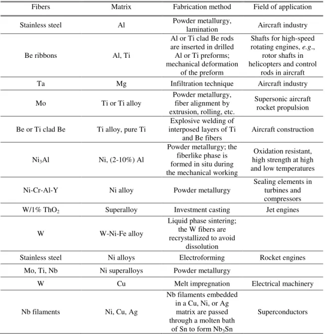
Table 2.2 – Metal matrix composite systems with metallic fibers [1].
Fibers Matrix Fabrication method Field of application
Stainless steel Al Powder metallurgy, lamination Aircraft industry
Be ribbons Al, Ti
Al or Ti clad Be rods are inserted in drilled Al or Ti preforms; mechanical deformation
of the preform
Shafts for high-speed rotating engines, e.g.,
rotor shafts in helicopters and control
rods in aircraft
Ta Mg Infiltration technique Aircraft industry
Mo Ti or Ti alloy
Powder metallurgy, fiber alignment by extrusion, rolling, etc.
Supersonic aircraft rocket propulsion
Be or Ti clad Be Ti alloy, pure Ti interposed layers of Ti Explosive welding of
and Be fibers Aircraft construction
Ni3Al Ni, (2-10%) Al
Powder metallurgy; the fiberlike phase is formed in situ during the mechanical working
Oxidation resistant, high strength at high and low temperatures
Ni-Cr-Al-Y Ni alloy Powder metallurgy Sealing elements in turbines and compressors
W/1% ThO2 Superalloy Investment casting Jet engines
W W-Ni-Fe alloy
Liquid phase sintering; the W fibers are recrystallized to avoid
dissolution
Stainless steel Ni alloys Electroforming Rocket engines
Mo, Ti, Nb Ni superalloys Powder metallurgy
W Cu Melt impregnation Electrical machinery
Nb filaments Ni, Cu, Ag
Nb filaments embedded in a Cu, Ni, or Ag matrix are passed through a molten bath
of Sn to form Nb3Sn
15
2.4.
Friction stir welding
FSW is a solid-state joining technology, in which a rotating tool with a shoulder and a pin moves along the faying surfaces of two rigidly clamped plates, faying surfaces are the inner compressed sheet interfaces (due to the mechanical axial forces applied by the tool). FSW joint configurations typically used are the ones depicted in figure 2.12 [32, 33]. The shoulder makes a firm contact with the surface of the work-piece; the heat generated, by friction of the shoulder and pin surfaces, softens the material being welded. Severe plastic deformation (SPD) and flow of this plasticized material occurs as the tool is traversed along the welding direction. Material is transported from the front of the tool to the trailing edge where it is forged into a joint [34].
Figure 2.12 – Illustration of butt (left) and lap (right) joint configurations: tool traverse and rotation movements depicted above.
The side where the speed of rotation is the same as that of traverse speed of the tool is called the advancing side (AS), with the opposite designated as retreating side (RS). The former is characterized by the positive vectorial sum of the tool feed rate and of the peripheral tool velocity; whereas in the latter the two velocity vectors are opposite. This difference can lead to an asymmetry in heat transfer and material flow. Since, a vertical movement of the material flow is desired, special tools have been designed to amplify this flow [35].
16
Figure 2.13 – Illustration of the four main zones in a transversal section of a friction stir welded bead. SZ – stirred zone, TMAZ – thermo-mechanically affected zone, HAZ – heat-affected zone, BM – base
material, AS – advancing side, RS – retreating side.
The stirred zone (or nugget) presents a severe plastic deformation and high temperatures, enabling dynamic recrystallization and producing an equiaxial grain structure. The asymmetric geometry of the nugget between the advancing (AS) and the retreating side (RS) results from unequal strain rates, creating a typical tail on the advancing side. Therefore, the advancing side has a higher plastic deformation and a reduced grain size. Reynolds [37] reported that the nugget zone was slightly larger than the pin diameter and as the pin diameter increases the nugget geometry acquired a more rounded shape, with a maximum diameter in the middle of the nugget. Mishra et al. [34] related the decreasing of recrystallized grain size with decreasing annealing temperature of the base material.
Thermo-mechanically affected zone (TMAZ) also experience high temperature and deformation during FSW, although deformation strain is insufficient to promote recrystallization and thus to develop a new crystal structure. TMAZ is characterized by an upward grain elongation, due to the stirred zone boundary. Thermal cycle experienced by TMAZ induces precipitate coarsening and dissolution.
The heat-affected zone (HAZ), is the least affected zone by FSW and is characterized by experiencing a thermal cycle but no plastic deformation.
17 Figure 2.14 – Diagram of FSP operating parameters.
Tool features induce the material flow around pin and shoulder. The mechanisms of material flow suggest that (a) surface friction between tool and material at the leading edge softens the base plate and initiates a plasticization swirl around the tool, (b) after the complete plasticization of the material, the heat is generated by the severe plastic deformation of the material whilst the friction of the shoulder, and to a lesser extent the pin, is negligible. It is the correct control of (a) and (b) that avoids common issues like excessive heat generation and stirring in welds [38]. It is fairly easy to realize that tool rotation vector has not only a great impact on the stirring action but also on the heat generated.
Known as the angle between the shoulder axis and the workpiece figure 2.15 a), the tilt angle (TA) enables a correct flow of material from the front to the trail of the tool. Higher TA results in a more dispersed softened material, the opposite in an inefficient material flow. It has been pointed as one of the least significant parameters [39-41].
18
Tool geometry is one key parameter for proper FSW runs. Tool design affects weld properties, defects and stress on the equipment – several tool geometries have been patented, especially for FSW, although they are currently designed empirically by trial and error [42, 43].
Important factors are shoulder diameter, shoulder surface angle, pin geometry, including its shape and size, and tool material nature. Shoulder generates the most heat, therefore its diameter is important, and its sticking action on the plasticized materials largely establishes the material flow field. The torque delivered by the tool has been studied to better understand the mechanics that affect the sticking of the tool interface. With increased temperature, flow stresses of the bead decreases and stirred area increases with the shoulder diameter. The product of these opposing factors leads to a maximum grip of the shoulder on the volume stirred [42].
a)
b)
Figure 2.15 – Plunge depth – PD (FSP parameter); a) Schematic illustration of PD, b) Effect of the PD variations from 0.15 mm to 0.4 mm in the right, rotational and traverse speeds were 900 rev/min and 63
mm/min, respectively [39].
A set of different surface shoulder patterns have been developed to enhance the material flow around the tool. Hirasawa et al. [44] studied flat, concave and convex tool shoulders, and cylindrical, tapered, inverse tapered and triangular pin geometries. Microstructure, geometry and failure threshold of a weld may be significantly altered if the tool
TA ()
19 shoulder chosen is concave rather than flat. On the other hand, pin threads on the surface influence the axial force of the tool on the processed plate and pin induced flow [45]. Fuji et al. [46] studied various tool shapes in FSW butt welds, for softer aluminium alloys a columnar tool pin without any thread would produce defect free welds – they also suggested that for less formable alloys, a triangular prism shaped tool pin would be more suitable. Zhao et al.[47] used columnar and tapered pins, both with and without threads. They observed that tapered threaded pins produced welds with the minimum defects in 2014 aluminium alloys. Another technique used to reduce the rapid tool wear of FSW joining of dissimilar materials is to plunge the tool in the softer material while avoiding contact of the tool and the harder material. This technique is setting the pace especially on lap joint FSW technique.
Softer aluminium alloys are especially interesting for reducing tool wear while increasing joint efficiency using this solid-state process. Aluminium alloys are by far the most widely used in metal–matrix because of its low density, low melting temperature (adequate for composite fabrication and joining), low cost and good machinability. Main applications include structures, heat sinks, substrates [2] and, recently, electric-conduction alongside with copper [48]. FSW of some aluminium alloys is especially interesting due to its difficulty in joining with fusion processes [40, 41, 49, 50]. Also, 5xxx alloys shows great improvement with heat generated in FSW, often above the dissolution temperature of precipitates, allowing reprecipitation, overaging and other tempering processes to occur [51]. AA 7xxx hard alloy series often suffers from brittle fracture, the implementation of FSW enhances the alloy ductile and stress-strain response [52].
On the other hand, commercially pure aluminium alloys (with more than 99% purity) have shown very little interest. Manisha et al. [12] developed new surface processing techniques (by FSP) for Al100 alloys, although with no further researches on this subject from 2007 onwards. Kurt et al. [53] also developed new ceramic coatings in pure aluminium matrices, more than doubling hardness with a SiC powder coating, although aluminium ease of formability and/or the heterogeneity of the material promptly created large amounts of flash, inconsistent weld beads and so on. Elrefaey et al. [54] pointed out several inner morphology defects in the welded zones, probably caused by slight pin depth differences along the weld bead. The overall research developed sound welds, with often occurrences of very underperforming joints. Few dissimilar material joints with unalloyed high purity aluminium have been also reported.
20
standard (IACS) ranks this high grade aluminium series as the best wrought aluminium alloy with 62 % of electrical conductivity, compared to the normalized value for annealed copper wire [55].
Cold worked pure aluminium has increased strength, but it does not support heat-treatments. Chemical equipment, heat exchangers, electrical conductors and capacitors,
decorative trim are a short-list of possible applications [11].
Threadgill et al. [51] exhaustive review on Friction Stir Welding is solely focused on aluminium alloys. According to author’s summary, a few interesting points on the use of this process can be listed:
(i) the absence of fusion state roughly reduces distortion of the welded beads, due to the non-existing thermal contractions associated with solidification and cooling;
(ii) highly flexible process, applicable in butt, lap or spot welding geometries in any dimension;
(iii) high welding rates. FSW con produce single-lap welds in thick materials, whereas other processes require multiple passes.
Due to the asymmetrical phenomena of FSW, the advancing side of the welded lap joints are often related to a pull effect, while the opposite, retreating side, pushes the material (interface). The pull effect resulted one of the most common defect in lap joints, figure 2.16, described as hooking and it occurs mainly on the AS, it is characterized by an upward rotation of the unwelded interface up to 90º [56]. On the opposite side, the RS experiences a plate thinning on the unwelded region, the sum of the shoulder induced flow and the pin induced (in volume) flow results in a pronounced bump of the base plate and a thickness reduction on the former plate. This can severely compromise the joint mechanical properties and integrity.
21 Percentage effective thickness (PET) is a term to quantify this thickness reduction, and is defined by equation 2.1 [56]. Figure 2.17 illustrates hooking and thinning after FSW, te is
measured from the Advancing hooking side.
(2.1)
Figure 2.17 – Illustration of hooking and thinning effects after FSW, te and to indicators for the percentage
effective thickness measurement.
There is a consensus that tool rotation speed (ω) is the major factor affecting the joint strength. Excessive rotation results in larger hooking size, lowering the joint strength [41, 54, 56-62]. A slight variation in this parameter may result in very dissimilar joint strengths. The pitch was lately found to be more relevant than the rotational speed [41]. With the same purpose, Yazdanian [56] studies the impact of this relation on the quality of the deformed faying surfaces. This was reported not to be a good indicator (two welding cross sections with the same pitch can be found in figure 2.18) same pitch but different set of rotation and traverse speed produced very dissimilar weldings. Nevertheless, with a fixed pitch, increasing the tool rotation augmented both the horizontal and the vertical material flow during FSW.
Figure 2.18 – Tranversal sections of welded lap joints with equal pitch values (0.127 mm.rev-1). Modified
22
Yazdanian reported the dependency of percentage effective thickness value on the HI. Lower HI resulted in higher PET, consequently deformed less material in the interface. High HI increased the pin induced material flow volume thus contributing significantly to the upward rotation of the original interface (hooking).
The tangential velocity of the material flow around the pin has to high enough for the material to refill the void created due to the tool movement. To achieve maximum lap shear strength, the rotational speed must hold at the lower end of possible range. Soudararajan et al. [57] shows that the void free weld formation takes place under a range of welding parameters for both the similar and dissimilar aluminium sheets joining.
On the impact of the pin height (PH) and plunge depth (PD), Elrefaey et al. [54] studied different pin depths in Al-Steel lap jointed alloys. With 2.0 mm of PH (tangent to the steel base plate), the joints exhibited very low strength; most of them failed during the preparation of specimens. Furthermore, a slight increase in pin depth (0.1 mm) had a significant effect on the performance of the lap joints. Several authors reported similar results for the pin height, Yadava et al. [41] achieved a maximum lap shear strength FSW with a pin of the same height as the sheet thickness. Although, Cederqvist et al. [60] showed that a shorter pin result in less pull-up on the retreating side of the weld. According to Yadava, PET values on AS and RS increased with increasing PD, this latter conclusion may validate the former.
A PD of 10%–20% more than the pin height would diminish hooking size in the AS, while for RS a smaller value of the PD would attenuate plate thinning, giving a higher effective thickness. An increase in pin height of the FSW tool in lap welding increases the pin penetration across the faying surface, alloying a more effective oxide disruption [41].
Such PD precision, in the tenths of millimeter, requires an accurate control of the plunge depth of the tool. It was found from previous study [57] that weld flash increases as the plunge depth increases and the weld crack occurs on the surface for plunge depth greater than 0.5 mm. Also, if contact between the shoulder and workpiece is lost during the weld formation, a crack develops. The plunge depth should be fixed when the process parameters are bounded within an upper and a lower limit.
23 with a broader tool shoulder and a concave pin end. Also, found lower fatigue thresholds for lap joints, against butt joint geometry.
Leal et al. [38] researched on the impact of the axial force during FSW. With the increasing in the axial force, with the remnant parameters fixed, defects appear in the surface only in the beginning (5xxx series annealed Al alloy). More, increase of the axial force was also responsible for a decreased of 15 % in the hardness of welded material.
Fersini et al. [64] tested for fatigue Al 2024 lap jointed alloys, reporting that failure occurred through the weld on the AS of the top sheet (Hooking side), and all of the specimens have ruptured this way – several reports conclude the latter [38, 65].
The possibility to eliminate the critical AS defect was proposed by Ericsson [62]. In this study, double pass welding have shown to increase joint efficiencies of lap welds substantially. Reason for this are the increased interface weld with, enhanced oxide disruption, and the hooking reduction, or elimination. Cederqvist et al. [60] showed that a double pass weld can provide higher joint efficiency (shear strengthened until failure), with strengths comparable to those of butt joints and higher than riveted joints – their results reveal the existence of a critical interface between the faying sheets, suggesting that a higher weld nugget would lower the secondary bending on overlapping, therefore a tool with a wider pin is beneficial in the case of overlap joints.
2.5.
Conclusions
This chapter introduced a technological background of the subjects investigated in this work. A thorough research on the most advanced processes and methodologies is presented. Composite materials proved to be beneficial for an extensive range of applications since they can combine the strengths of involved materials. Development of technologically different joining methods is crucial for material engineering. Solid state techniques have pushed forward on new welding possibilities and properties. FSW is amongst these, the capability to join materials bellow fusion point is of great advantage for critical alloys, such as aluminium and NiTi.
25
3.
EXPERIMENTAL PROCEDURE
3.1.
Materials
AA 1100 aluminium alloy sheets were used as substrate. The following tables 3.1 and 3.2 display the chemical composition, mechanical and physical properties for this alloy.
Table 3.1 – Chemical (wt.%) and mechanical properties of AA 1100 [11].
Element Al Si + Fe Cu Mn Zn Other
Max - 1.00 0.20 0.05 0.10 0.15
Min 99.00 - 0.05 - - -
Temper UTS (MPa) Yield strength (MPa) Elongation at break
(%) Hardness (HB)
O 90 34 35 23
as-received
AA 1100 56 35 33 -
Table 3.2 – Physical properties of AA 1100 [11, 66].
Alloy Density (g/cm3)
Thermal properties Electrical properties
Coefficient of thermal expansion (µm/mK) Thermal conductivity
(W/ mK)
Annealing temperature (ºC) Melting point (ºC) Electrical condutivity (% IACS) Electrical resistivity (nΩm)
1100 2.7 23.6 218 to 222 343 646 57 to 64 59
The as-received sheets were guillotined, from the original 1.6 mm thick plate into rectangular samples, of 50x200, 100x100 and 50x100 mm.
26
Table 3.3 – NiTi alloy specifications [11].
Chemical composition (at.%)
Element Ni Ti
Max 51 52
Min 49 48
Mechanical Properties
UTS (MPa) Yield strength (MPa) Elongation at break
(%) E (GPa)
Austenite 895 195 to 690 15.5 83
Martensite 895 70 to 140 15.5 28 to 41
Physical properties
Density (g/cm3)
Thermal properties
Electrical resistivity (nΩm) Thermal conductivity
(W/ mK)
Melting point (ºC)
Austenite 6.45 18.0 1300 100000
Martensite 6.45 8.5 – 70000
The NiTi ribbons presented an oxidized surface and no superelastic plateau, therefore the as-received material was subjected to a heat treatment prior to composite production (the tensile testing results of the as-received NiTi alloy are further discussed in section 4.1). After heat treating at 500 ºC for 20 minutes, the NiTi ribbons austenitic phase changed to a martensitic phase, at ambient temperature, therefore altering its microstructure. Figure 3.1 shows the stress-strain response curve, a martensitic reorientation plateau is depicted. The reheated ribbons depicted an overall UTS reduction from the initial 1096 to 924 MPa together with an elongation at break increment of 211 %.
Figure 3.1 – Stress-strain curve of NiTi after heat treatment at 500 ºC for 20 minutes. 0 200 400 600 800 1000
0 1 2 3 4 5 6 7 8 9 10 11 12 13 14 15 16 17 18 19
27 Steel wires of 0.8 and 1.0 mm diameter were used to study the effect of processing parameters on the processed depth, homogeneity of weld bead, among others. Those have remarkable low price when compared to NiTi and allowed to test the effect of sample configuration and positioning method on the bonding mechanism.
For this, a low alloyed steel wire was used with the mechanical properties shown in table 3.4
Table 3.4 – Mechanical properties of steel wire (AristoRod™ 12.5) [67].
UTS (MPa) Yield strength (MPa) Elongation (%)
560 470 26
3.2.
Equipment
In order to produce MMCs with embedded wires, a two stage joining process was implemented: First, the preform of the aluminium alloy base plate was produced with three different methods (to test and devise a proper groove opening technique); secondly, reinforcements were positioned into the base plates in a lap joint configuration and Friction Stir Welded.
Pre-processing comprised three different techniques: (a) A scriber, made from hardened and tempered tool steel; (b) a milling machine equipped with a HSS 10 mm diameter two flute end mill, the milling head supports an angle variation (the normal to worktable rotating axis admit a parallel position to the worktable, from -90º to +90º), and the groove opening required a 45º angle working condition; (c) a 100 ton manual hydraulic press machine equipped with specially designed steel plates, to endure the pressing conditions while forming the AA 1100 aluminium alloy to their correct shapes.
For the aluminium composites production, an ESAB machine with three degrees of freedom, LEGIO™ 3UT model, for Friction Stir Welding was used.
28
Figure 3.2 – Sample set up and degrees of freedom in FSW machine.
The worktable and the machine frame are fixed, as shown above, while the human machine interface (HMI) console, the power unit and the welding head move along the X and Y-axis. An internal water refrigeration system passes through the machine’s spindle shaft up to the welding tool upper interface. Tilt angle (TA) can be changed by a set of screws. The tilt angle has a limit of 5º in a single direction. The HMI panel controls every other variable, apart from the TA.
A set of parameters can be manipulated during operation, or pre-set and saved for automation purposes, and these are:
- Traversal velocity (cm/min) - Rotational velocity (rev/min) - Tool force (Kg)
- Plunge depth (mm) and speed (mm/s), normally negative because is downwards - Dwell time (s)
- Control method (force or position control)
Y-axis X-axis
Z-axis
Rotating axis
Sample FSW tool
29 FSW Tool
A special tool, developed and patented by Santos and Vilaça, at IST-UTL, was used [69]. Figure 3.3 shows a tool for welding processes, compact and modular disposable, allowing different combinations of geometric parameters between shoulder (1) and pin (2). It supports the FSW machine water cooling system (3) with an inner chamber close to the upper pin interface. It can be adjustable to different thickness of weld plates by changing the pin height. The system is composed of a body tool (4), a built-in shoulder (1), an adjustable pin (2), screws fixing the shoulder (5), and a threaded stud fixing pin (6). Machine spindle shaft and fixturing system are comprised by (7) and (8), respectively.
Figure 3.3 – Patented modular tool, (a) section view of the entire piece, (b) section view of the pin and shoulder [70].
The adjustment of the pin height (2) is made by screwing or unscrewing the shoulder from the tool body. The tool body material is DIN Ck45 steel, shoulder and pin are in AISI H13 tool steel. Figure 3.4 shows the FSW tool used in this investigation. The pin was easily adjustable to the required depth since the tool has a modular design.
Figure 3.4 – FSW used tool, 18 mm diameter plain shoulder with one two-lap ridge, and a 5 mm diameter threaded cylindrical pin.
1 2
3
4 6
5 8 7
5
1
30
FSW Fixturing system
The amount of force transferred to the welded material and worktable from the FSW equipment requires a suitable fixturing system. Torque generated during FSW induces high shear strength around the tool pin that, if not strongly constrained, would spin the welded plates around the tool. On the other hand, excessive aperture forces on the base plates may sometimes cause unwanted bulges, a set of plates have been designed to even the distributed the aperture pressure along the material. The clamping system, used mainly in multi lap FSW was mounted on the worktable support blocks to adjust height as presented in figure 3.5.
a)
b)
Figure 3.5 – Fixturing equipment, a) group of plates with a maximum of aperture, b) clamping system on worktable of the FSW equipment.
31
3.3.
Working methodology
3.3.1.
Sample preparation
Aluminium plates were mechanically worked for opening the groove, grinded, cleaned with alcohol and mounted in the FSW worktable. Three different methods were used for opening the groove. Figure 3.6 illustrates the groove geometries used.
a) b)
c) d)
Figure 3.6 – Cross sections of base plate with metallic reinforcements before FSW. a) “V” type cross section shape groove, b) round cross section shape, opened with a 1,0 mm diameter steel wire, c) round cross section shape, opened with a 0,8 mm diameter steel wire, d) rectangular 1,1 x 3,5 mm cross section.
(a) A scriber was firmly pressed along the length of the specimen; the straightedge of the groove line was maintained with the help of a metallic set square. The groove section is defined by a “V” type geometry.
(b) The milling machined specimens resulted also in a “v” shaped geometry, as shown in figure 3.6 a). The working parameters were: 12 cm/min and 600 rev/min for traversal and rotational speeds, respectively.
(c) The last groove opening technique used was the one adopted throughout the investigation. The 100 tons hydraulic press produced fine results at 25 ton axial force; figure 3.6 b), c) and d) illustrate the type of geometries produced with this technique. Two mild steel base plates were used in the hydraulic press. Those were first rectified, grinded (with 400 SiC waterproof abrasive grinding paper) and cleaned until no particles or bulges remained. To create the round and rectangular shaped grooves, onto the AA 1100 base plates, AristoRod™
~1.90 mm
~3.50 mm ~1.10 mm
![Figure 2.4 – Young modulus plotted against density for various engineering materials [7]](https://thumb-eu.123doks.com/thumbv2/123dok_br/16552795.737226/26.892.135.765.243.674/figure-young-modulus-plotted-density-various-engineering-materials.webp)


![Figure 2.16 – Lap weld defects showing hooking on advancing side and plate thinning on retreating side in lap welds between AA 7075 (upper) and AA 2024 (lower) alloys [51]](https://thumb-eu.123doks.com/thumbv2/123dok_br/16552795.737226/40.892.212.683.850.1050/figure-defects-showing-hooking-advancing-thinning-retreating-alloys.webp)