A reconfigurable computing system
for an autonomous sailboat
Jose C. Alves, Nuno A. Cruz
Department of Electrical and Computer Engineering
University of Porto
Porto, Portugal
{jca,nacruz}@fe.up.pt
Abstract
This paper presents the computing infrastruc-ture used in an autonomous unmanned small-scale sailboat. The system is build on a reconfig-urable FPGA and includes custom designed inter-faces for the various sensors and actuators used in the sailboat. The central processing unit is a 32-bit RISC microprocessor (Microblaze from XILINX) implemented as a soft IP (Intellectual Property) core, running at a maximum frequency of 50 MHz. The computing system runs uClinux, a simplified version of the popular Linux operat-ing system. The usage of a reconfigurable plat-form enables the possibility to reconfigure com-pletely the processing and control hardware sys-tem. This facilitates enormously the development of the control system and allows the selection of different hardware control systems, according to the navigation requirements and environmental conditions.
1.
Introduction
The FEUP1 autonomous sailboat (FASt) is a small
sailing yacht capable of fully autonomous navigation through a predefined set of waypoints. The boat was custom designed and built as a response to the Micro-transat challenge and offers a flexible platform for var-ious applications like data acquisition of oceanographic or atmospheric variables, wild life tracking and moni-toring, surveillance and also support platforms for co-operative navigation with autonomous underwater vehi-cles (Curtin et al., 1993) (AUVs).
1.1
Sailing
Sailing can be an easy task or a very complex task, de-pending on the desired level of performance and also on the wind and sea conditions. In conventional sailing
1Faculdade de Engenharia da Universidade do Porto (School of
Engineering of the University of Porto)
boats the basic controls are the rudder and sail sheet. The rudder determines the course to navigate and the sail sheet is used much like the throttle of a car: loose it to stop the boat or pull it to go ahead. For a given course, boat speed, wind speed and wind direction, there is an optimum angle between the sail and direction of the wind that maximizes the speed of the boat. If the boat speed changes (for example, slowing down when climb-ing up a wave or acceleratclimb-ing by surfclimb-ing a wave) the apparent wind direction and wind speed relative to the boat are modified, implying constant corrections to the sail angle to maintain the course with optimum speed. Alternatively, the sailor can keep the sail in the same position and alter the course with the rudder to keep the same apparent wind angle. Also, variations in the true wind speed due, for example, to the waves (wind speed increases in the crest of a wave), add important variations to the wind conditions seen by an observer on the boat. This results in the necessity of continuously adjust the sail and/or the rudder to keep the boat at its maximum speed. In addition, conventional fabric sails also have control lines that are used to adjust the shape of the sail, depending on the leg sailed (up-wind, down-wind), wind speed and sea condition. Although this is a simplified view of the close interactions that exist be-tween the variables involved in the sailing process, it is clear that a control procedure should adapt dynamically to the environmental conditions.
Sailors have from several years the assistance of auto-pilots to provide autonomous steering, for limited peri-ods of time. In a sailing yacht the electric energy is usu-ally limited and the normal sources of power are the sun and the wind. If the boat is well balanced with respect to the various forces involved, the amount of energy re-quired to steer it can be relatively small. The auto-pilot is a valuable accessory in sailing yachts, allowing the automatic control of course according to some reference direction (GPS, compass or wind direction). One type of fully mechanical auto-pilot is the wind-vane self steering system, very popular some decades ago (Belcher, 1982) and still in use by some sailors for long journeys. It
com-bines a wind vane mechanically linked to a rudder and steers the boat automatically, relative to the apparent wind. Although this system has some limitations, it has the big advantage of not requiring any electric energy for working.
1.2
FPGAs
The computing system designed for FASt is based on a FPGA (Field-Programmable Gate Array), providing a flexible reconfigurable computing plat-form (Compton and Hauck, 2002). The system includes a RISC 32-bit central processor surrounded by a set of custom designed peripheral digital systems that implement the processes responsible for interfacing with sensors and actuators, and also for custom processing and control. This allows the integration of almost all the custom digital electronics into a single chip and simplifies significantly the design of the control software, alleviating the processor from the low-level interfacing and data processing tasks.
FPGAs are commercial integrated circuits that can be configured by the end user to perform any arbi-trary digital system. The common configuration tech-nology used in present FPGAs is based on SRAM and provides a virtually infinite number of re-configurations in very short times (tens to hundreds of milliseconds). Cutting-edge FPGA devices offer capacities equivalent to a few millions of logic gates, and include on-chip memory blocks exceeding 10 Mbit, dedicated functional blocks optimized for signal-processing applications, giga-bit transceivers and, in some families, embedded high-performance processors. Furthermore, the digital sys-tems implemented in such devices can run with clocks of a few hundreds of mega-hertz and exceed one thou-sand input/output pins available for the user applica-tion. This is now a mature digital technology that of-fers flexible platforms for targeting complex and high-performance digital systems without incurring in the high costs and long turnaround times of silicon fabri-cation.
Another interesting attractive of FPGA technology is the ability to quickly modify the digital system imple-mented in the chip. Different configuration files can re-side in low cost off-chip flash memories (or hard disk) and loaded into the FPGA to perform a completely different system. Some FPGA families even allow partial recon-figurations without disturbing the rest of the chip. This is particularly interesting in applications where the pro-cessing requirements may vary along the time and also during the development and experimentation stages.
1.3
Paper organization
In addition to this introduction, the paper is organized as follows. Section 2. briefly presents the autonomous
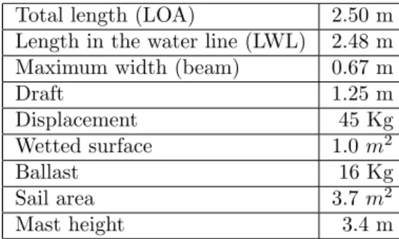
Total length (LOA) 2.50 m Length in the water line (LWL) 2.48 m Maximum width (beam) 0.67 m
Draft 1.25 m Displacement 45 Kg Wetted surface 1.0 m2 Ballast 16 Kg Sail area 3.7 m2 Mast height 3.4 m
Table 1: Main dimensions of the FEUP Autonomous Sailboat - FASt
sailboat built at FEUP (FASt). Section 3. overviews the electronic system used in FASt and the hardware plat-form that implements the main computer is presented in section 4.. The computing system is detailed in sec-tion 5., including the sensors and actuators. Main imple-mentation results are presented in section 6.. Section 7. summarizes the operating modes supported by the FASt control system and finally section 8. concludes the paper and presents the current status of the project.
2.
The FASt project
The FASt project was launched at FEUP in the begin-ning of 2007 to participate in the Microtransat com-petition. The project aimed to build a small-scale au-tonomous sailing boat with two objectives in mind: min-imize the energy required for sailing and navigate as fast as possible. Although the Microtransat rules establish a maximum length of 4m and the theoretical maximum speed of a boat is proportional to the square root of its length, we decided for a 2.5m long mono-hull. This was determined after scaling down in length and displace-ment some real oceanic modern sailing boats, to keep the final weight not far from the 40Kg mark, in order to facilitate the launch and transportation either by towing or on the top of a car.
The design was inspired on the modern racing oceanic yachts and was developed with the free version of the boat design software DelftShip (Delftship, 2008) (former FreeShip). The hull bottom at the stern is flat to induce planning. To increase stability, the boat includes a deep keel with a ballast. The rig is a standard Marconi config-uration with a small jib mounted on a boom, as used in smaller RC sailing boats. Main dimensions are presented in table 1.
2.1
FASt hull construction
The boat was built by a team of students and pro-fessors of FEUP, with the support of a local kayak builder (Elio, 2008) that executed the fabrication of the parts in composite materials and gave a valuable help during all phases of the process. The construction
started in the beginning of March 2007 with the assem-bly of the positive model. This was built starting with plywood frames, a rough cover of strip planking and fi-breglass with polyester resin, followed by various iter-ations of filling and sanding to achieve a final smooth surface. This full scale model was then used to build a negative mould and, afterwards, the final hull.
The hull has been fabricated using a sandwich of car-bon fibre in the outer layer, a low density honey comb core in the middle and a inner layer of fibreglass. This sandwich was pressed with vacuum during the cure of the epoxy resin. This is the same construction process used to build high-performance racing kayaks and resulted in a very stiff hull, weighing less than 5kg, without the deck. The hull was reinforced internally at the points subject to the major mechanical forces: the attachment of the keel, foot of mast and the points where the shrouds connect to the hull. Two platforms placed at the bot-tom interior (front and middle) provide convenient space for mounting the electronic system. Figure 1 illustrates some stages of the construction process.
The keel was manually built starting from a core of rigid polyurethane foam shaped to a NACA profile, then laminated in vacuum with several layers of carbon fi-bre. The rudders were made from a wood core covered by fibre glass, firmly attached to a stainless steel shaft. Mast and boom were built with carbon fibre tubes used in competition paddles and some standard hardware of masts of small dinghies.
3.
Electronic system
The electronic system used in FASt is assembled with various modules, some of them custom built for this ap-plication. Figure 2 presents a block diagram showing the general organization of the system and the approximate physical location inside the hull.
The computing system is implemented in a small FPGA-based single board computer (Atmark-Techno, ). This includes a 32-bit RISC microprocessor run-ning at a 50MHz maximum clock frequency (Microb-laze (Microb(Microb-laze, )), surrounded by various custom de-signed dedicated circuits. The organization, character-istics and modes of operation of the computing system are detailed in the next sections.
The communications section includes a WiFi router (LinkSys WRT54GC), GSM modem (Siemens MC35), IRIDIUM SBD modem (model 9601) and a conventional RC receiver used in radio-commanded models. All these components are integrated as OEM modules and can be switched on/off under control of the software running in the computing system, depending on the operating mode of the system.
Sensors include the wind vane and anemometer, boom position, compass (Honeywell HMR3300), GPS (uBlox RCB-4H), inclinometer (two axis accelerometer
Figure 1: The construction of FASt: (top-left to bottom) assembly of the frames, strip planking, the mould, filling the mould with the layers of fibere and core materials and the final hull.
ADXL202, from Analog Devices), voltage monitors, am-bient light sensor, interior temperature (Analog Devices A/D converter AD7905) and a set of moisture sensors custom made with small pieces of gold plated PCB ter-minals. A total of 4 additional A/D channels and 16 dig-ital I/Os are available for future expansion. The wind vane and boom position indicator were built with a mag-netic field sensor AS5040 from Austria Micro Systems. This chip measures the orientation of the magnetic field of a small magnet placed close to its case and provides 10 bit measures with 1 degree of accuracy. The chip was embedded in epoxy resin and is thus completely isolated from the water. The wind speed sensor is made with a conventional cup rotor actuating a hall-effect switch also embedded in epoxy.
Regarding the actuators, one DC motor controls the sail’s position and two standard RC servos provide inde-pendent control of the two rudders. A second DC motor
Figure 2: The organization of the FASt electronic system and its distribution inside the hull.
is planned to be installed for adjusting the sail area. The DC motors are standard window motors used in cars. Although this type of motor and the associated gear-box is known for its low efficiency, they are extremely robust and once positioned and unpowered the gearbox naturally locks the motor’s shaft. As the sail angle only needs to be adjusted to set a new course or when the wind direction changes significantly, this represents an important saving of electric energy when comparing to other combinations motor-gearbox that need power to react to the force of the sail sheet.
Finally, the power generation and control section in-cludes a 48Wp solar panel (Solara SM160M), a pack of Li-ion batteries, battery charger and DC-DC converters to provide all the voltages used by the rest of the sys-tem. This part is still under development at the time this paper is being written.
4.
The computing platform
The computer board used in FASt is a commercial system from Suzaku (SZ130 (Atmark-Techno, )), built around a Xilinx FPGA, model Spartan3E S1200. The system has 32 MB of SDRAM, 8MB of SPI flash mem-ory, serial interface and Ethernet port implemented by a dedicated chip external to the FPGA. A total of 86 I/O pins are available for the user application, directly connected to FPGA I/Os and distributed in edge con-nectors around the board. The FPGA is only partially occupied by the base project (processor and essential pe-ripherals), leaving roughly more than 1 million equiva-lent logic gates available for user logic. Figure 3 depicts the organization of the SZ130 board and the reference project implemented in the FPGA.
The system runs uCLinux (www.uclinux.org), an-other version of the popular Linux operating system that has been simplified and adapted for embedded applica-tions running in processors with no memory
manage-ment unit (MMU). The operating system provides an interactive console through a standard RS232 port, a structured file system, multitasking and basic TCP/IP services (FTP, HTTP and TELNET).
Figure 3: Organization of the Suzaku SZ130 board.
This board constitutes a convenient platform for build-ing a digital integrated system, providbuild-ing a combined hardware/software solution for a given problem. A de-sign may include virtually any custom dede-signed digi-tal circuit that may fit into the FPGA’s free resources. Combining conventional software execution with custom processing by dedicated hardware modules can alleviate significantly the computing load of the central micro-processor. Besides simplifying the development of the software (some of concurrent processing tasks are done transparently in hardware), this approach also permits to reduce the processor’s clock frequency and thus the overall power consumption.
4.1
Software development
The software for this machine is developed in ANSI C and compiled with a customized version of gcc. There are two levels of software that may be developed, de-pending on the usage or not of the underlying uCLinux
operating system. A stand alone program can be created with the compiler embedded in the XILINX EDK tools and integrated with the configuration data of the FPGA. When the FPGA boots, that program is started auto-matically and allows only basic console I/O. In this case, the uCLinux operating system is not started and thus there is no support for TCP/IP and file system services. The development of programs to run on the uCLinux operating system can make use of the most common Linux standard libraries, including TCP/IP communi-cation, file I/O and file system management. The com-pilation is done on a conventional Linux machine and transferred to the Suzaku board via FTP or through the RS232 serial interface.
The uCLinux file system is locally stored in the flash memory and loaded into a segment of the SDRAM (con-figured as a RAM disk) during the boot process. An image of the file system is maintained in the computer with the development system. The modifications of the uCLinux file system are done in this image and trans-ferred to the Suzaku flash memory with appropriate com-mands.
During development, evaluation and debug, the sup-port of such an operating system is a convenient solution because it eases the implementation of network commu-nication processes, file management and eases the mul-titasking of different program’s parts. However, for ap-plications requiring low power consumption, running on the top of an operating system may represent a signifi-cant overhead for the global power consumption. From this point of view, running a stand alone program may be a better solution. Both approaches are conveniently supported by this platform.
4.2
Hardware development
The development of the digital system implemented in the FPGA is done with the EDK/ISE software tools from XILINX. The XILINX EDK (Embedded Devel-opment Kit) is a design tool that builds a combined hardware/software design, targeted to a XILINX FPGA-based board. The hardware part is assembled with pre-designed parametrizable modules (microprocessor, SDRAM interface, USART, etc.) and user designed com-ponents. The software part is built as a C program that will be later embedded with the FPGA configuration data. The ISE tool suite performs the complete digi-tal design flow for XILINX FPGAs and translates the circuit models produced by EDK into the final FPGA bitstream.
To attach a user-defined digital block to the micro-processor, the library of modules include general pur-pose I/O interfaces that attach to the microprocessor buses. A user’s circuit is specified in standard hardware description languages (Verilog or VHDL) and integrated into the system’s top-level description.
4.3
FPGA reconfiguration
When the system is powered up, the FPGA is config-ured with the data stored in the beginning of the flash memory. Once the configuration is completed (less than 1 second), the I/O buffers associated to the FPGA pins are enabled and the system implemented in the FPGA starts running (freeing an internal global reset). The Mi-croblaze microprocessor runs the code stored internally in the FPGA memories. If the startup of the uCLinux is enabled (the original configuration), then a boot loader is executed that loads the file system image stored into the flash to the SDRAM, builds the uCLinux file system and loads the operating system kernel. The complete pro-cess, from power-up to system idle state, takes approx-imately 42 seconds, running the Microblaze at 50MHz (76 seconds if running at 25MHz).
The reconfiguration of the FPGA can be done easily under control of software. Under uCLinux, the section of the flash memory that holds the FPGA configuration data (usually called bitstream) can be re-written from a regular file stored in the file system, using one applica-tion included in the file system distribuapplica-tion. The run-ning software can thus choose a bitstream from a batch of pre-built configurations, copy it to the flash memory and issue a reboot command to restart the system with a different FPGA configuration.
This unique feature of FPGA-based systems allows to change the digital circuit played by the FPGA, accord-ing to different processaccord-ing needs that may be driven by several factors (eg. the availability of energy or environ-mental conditions). This is not yet being exploited in FASt, although it may be a good strategy for reducing the energy consumption.
5.
The FASt computing system
The FASt computing system is implemented in the FPGA of the Suzaku board. Besides the central Mi-croblaze processor, the system includes various dedicated controllers for interfacing the sensors and actuators used in the sailboat, some of them associated with custom computing modules. Figure 4 presents the general orga-nization of the system.
The global strategy adopted during the design of this system was to create a set of autonomous interfaces ca-pable of delivering to the software the data retrieved from the sensors in a format easy to be integrated in the software control system. Besides the implementa-tion of the sensor’s specific interface protocols, this in-cludes parsing messages from the sensors, filtering, and units conversion. Although simple averaging filters have been implemented for the wind sensors and acceleration (inclinometer), there is enough room to include higher quality low pass filters.
Figure 4: Simplified view of the organization of the FASt computing system implemented in the FPGA. All the sen-sors and actuators are accessed by the microprocessor via dedicated interfaces. The two shaded blocks are standard se-rial port controllers implemented as pre-built modules from the EDK library.
done through a port expander. This module uses only one pair of 32-bit memory-mapped bidirectional ports and makes available for the rest of the circuit a set of eight output ports and 16 inputs ports (32-bit each). This is implemented as a finite-state machine that inter-prets a set of simple commands issued by the micropro-cessor as memory writes and reads.
5.1
Sensors
The wind direction interface reads the ASS5040 sensor sampled at 50Hz and averaged using a sliding window of 64 samples (the boom position sensor is built with the same chip and is interfaced by another instance of this module). The output is an integer in the range [-180,+180] and the position of the direction reference can be corrected with an offset defined by software. The interface with the wind speed sensor outputs the number of 10KHz clock periods during one revolution of the cup rotor, sampled at 10Hz and averaged by a 64 tap mean filter.
The inclinometer reads the PWM outputs of the 2-axis accelerometer and returns two integers that are propor-tional to the X and Y acceleration. These values are sampled at an frequency approximately equal to 100Hz, dictated by an RC network in the accelerometer board. These values are averaged with 128 tap average filters.
The magnetic compass provides the complete data (heading, roll and pitch angles) in ASCII format, as vari-able sized messages. Although the ASCII format is easy to interface with a software function, it is also impor-tant to have access to this data, from the hardware side, in numeric digital format. This allows for future inte-gration of hardware control processes that directly link the heading/roll/pitch information to the controllers of the steering servos. This interface implements a parser
of the messages sent by the compass and performs the conversion ASCII to binary. The GPS interface is done in a similar way, extracting the relevant data (lat/lon, speed, course and status) from the binary protocol out-put (uBlox UBX protocol (u Blox, 2008)).
The interface with the radio-control receiver is done by 4 instances of the same controller, one for each chan-nel of the radio. The standard control signal used in RC receivers and servos is a 50Hz digital signal, where the high time defines the position of the servo (ranging from 0.8ms to 2.2ms). Each receiver module measures the high time of the corresponding channel and converts it to a two’s complement 10 bit integer: zero means the control stick at the middle, +511 is full right (full front) and -512 is full left (full rear). One additional mod-ule monitors continuously the signal received from radio channel 1, looking for 8 consecutive valid pulses (crite-ria for valid pulses is frequency between 45 and 55 Hz and high time between 0.5 and 2.5ms) to assert a radio present signal. This notifies the rest of the system that the RC transmitter is in range and transmitting correct data.
The system includes an A/D converter with 6 analog inputs, plus two additional channels that monitor of the 3.3V supply and the chip temperature (AD7795). This is interfaced with a controller that implements the SPI and provides to the computing system a simpler interface to select a channel and read the conversion result.
5.2
Actuators
The servo controllers receive a 10-bit two’s complement number and generate the 50Hz standard control signal, according to the timing referred above. For the moment, only two servos are being used for the two rudders, al-though additional servo controllers can be easily added. A hardware multiplexer selects the source of data that is routed to these servos: this can be the output of the RC channel 1 (to use the left-right stick) or the data sent by the software application running on the processor.
The sail sheet of both sails is commanded by one DC motor with a multi-turn potentiometer for position feed-back. This motor is controlled by a PWM modulator that drives one power bridge assembled with MOSFET power transistors. The PWM module include a low-pass filter applied to the input data, to avoid high accelera-tions that result in high current draw. Another PWM modulator is included to support the control of the sec-ond DC motor.
6.
Implementation
Current design, as represented in figure 4, uses less than 50% of the XC3S1200E FPGA resources and corresponds approximately to 1 million equivalent logic gates. All the modules support the maximum clock frequency of
4-input LUTs 7,314 (42%)
Flip-flops 3,997 (23%)
Occupied slices 4,730 (54%) LUTs used as route-thru 324 (1.8%) LUTs used as SRAM 256 (1.5%) LUTs used as shift-registers 796 (4.6%)
Block RAMs 14 (50%)
Dedicated multipliers 8 (28%) Equivalent gate count 1,078,257
Table 2: Summary of the FPGA occupation (Spartan 3E 1200)
50MHz allowed for the Microblaze processor, although most of them can run with much lower frequencies. Ta-ble 2 summarizes the occupation of the FPGA resources.
6.1
Power consumption issues
Electric power consumption is one of the great concerns in an autonomous sailboat. For a small boat, the reason-able sources of electric energy for long term navigation are photovoltaic panels and wind turbines. Best solution would be a combination of both but, as far as we know, the commercially available wind generators are too large and heavy for our sailboat. In both cases, the availabil-ity of energy always depends on the weather conditions which still have a high degree of uncertainty. The elec-tronic system must consume the lowest possible energy and whenever possible adapt its behaviour to the power budget available at each stage.
According to our first estimates, the computing sys-tem will account for more than 50% of the total energy consumed by the system, assuming a continuous oper-ation with the maximum power consumption measured for the present configuration. This represents aproxi-mately 500mA for the 3.3V supply (1.65W, including 100mW for the digital compass and the wind sensors) running the microprocessor at the maximum frequency of 50MHz with the Ethernet port enabled. Disconect-ing the Ethernet cable puts the Ethernet controller in power down mode and reduces the power consumption by approximatley 200mW; lowering the clock frequency to 25MHz saves more 100mW. The reconfiguration fea-ture of the FPGA-based system can be exploited to fur-ther enhance the power management strategy. For ex-ample, once a course and sail position has been defined, the steering control can be made by a simple controller implemented directly in hardware the FPGA, disabling the microprocessor and all the peripherals not in use.
7.
Operating modes
The FASt computing system supports three different modes of operation, depending on the purpose of the
navigation. The selection of the control mode is done by the throttle level of the radio-command: mid-dle for radio-commanded mode, front for WiFi semi-autonomous control and rear for fully semi-autonomous sail-ing. When the radio transmitter is switched off, the boat enters automatically the fully autonomous mode, and checks for the presence of the RC radio signal at periodic intervals (this is currently set to 1 minute but can be software programmed). At the time this paper is being written, the two last operating modes were only implemented in a simulation program.
The simplest mode is the radio-commanded control mode, where the control is totally done through the radio-command, using only two control sticks: left-right turn and sheet control. In this mode, FASt behaves as a conventional RC sailing boat and logs the information received from the sensors, as well as the position of rud-ders and sail defined by the operator. Is this mode, the WiFi link is active and the status of the boat can be monitored in real time from a computer in range of the wireless network.
The semi-autonomous mode is enabled by setting the throttle lever to the front position. This mode requires additional commands sent from a control program run-ning in a PC in the range of the WiFi signal. Route con-trol is done by the software running in FASt, by defining remotely the desired heading, course or apparent wind angle. Sail control can be done manually (the user spec-ifies the boom angle) or autonomously, according to the rules established in the software for a given apparent wind angle. The tack and jibe maneuvers are performed automatically by the software running in FASt, upon request of the operator.
In the fully autonomous mode with the presence of the RC radio signal, the WiFi router is enabled and the operation of FASt can be monitored in real time from the remote PC. If the RC signal is not present, the electronic system switches off the WiFi router and the RC receiver, and starts the fully autonomous navigation to round a set of pre-programmed waypoints.
The first two modes are convenient during the devel-opment of the software and tuning of the control param-eters. The short range of the WiFi link and radio control limits the operation of the boat to within a few hundred meters, even though these modes of operation are only intended to be used under visual operation.
8.
Conclusions
This paper presented a FPGA-based reconfigurable elec-tronic system used in an autonomous sailing boat. The FPGA implements the computing part and includes a RISC microprocessor surrounded by several custom de-signed peripherals that interface with the sensors and actuators used in the sailboat. The hardware reconfig-urability feature of the FPGA enables a short design
iteration and allows fast reconfigurations of the running hardware. This may be exploited for minimizing the energy consumption by adapting the control and com-puting logic circuits to the specific requirements of nav-igation under given wind and sea conditions.
By the time the paper is being written (middle March 2008), and more than one year after starting the con-struction, the boat is almost ready for the first tests in water. Designing and building a new boat from scratch was a challenging and time consuming task, specially being a first prototype. We hope that an efficient au-tonomous sailing platform will open, in a near future, in-teresting opportunities for applications in various fields.
Acknowledgements
The authors would like to thank the Department of Electrical and Computing Engineering (DEEC) of the School of Engineering of the University of Porto, Portu-gal (FEUP), for the financial support of this project.
References
Atmark-Techno. SUZAKU-SZ130-U00, hardware manual, v1.0.2.
Belcher, B. (1982). Wind-vane Self-Steering. Interna-tional Marine Publishing Company.
Compton, K. and Hauck, S. (2002). Reconfigurable computing: A survey of systems and software. ACM Computing Surveys, 34(2):171–210.
Curtin, T., Bellingham, J., Catapovic, J., and Webb, D. (1993). Autonomous oceanographic sampling net-works. Oceanography, 6(3):86–94.
Delftship (2008). http://www.delftship.net. Elio (2008). Kayak builder, elio kayaks web page
http://www.eliokayaks.com.
Microblaze. Microblaze processor reference guide, UG081, V8.0 (EDK 9.1i).
u Blox (2008). NMEA, UBX Protocol Specification, u-Blox 5 GNSS receiver, public release.